Advertisement
Quick Links
Download this manual
See also:
Manual
Advertisement

Related Manuals for Velleman K4040


Summary of Contents for Velleman K4040
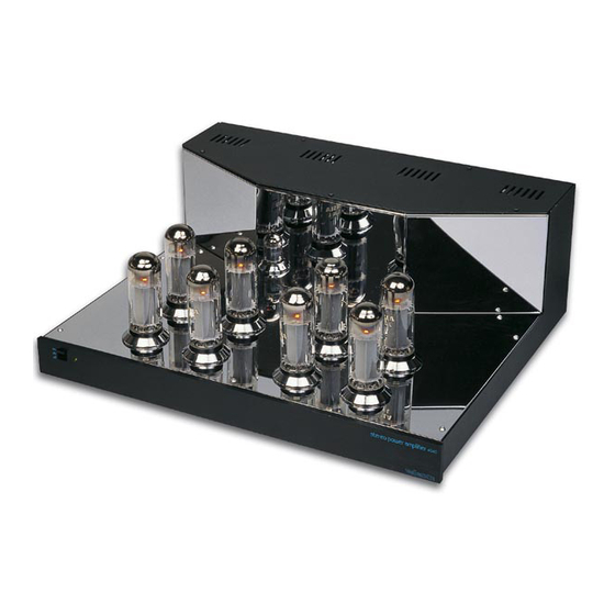
- Page 1 Stereo valve power amplifier Total solder points: 700 5 ⌧ advanced Difficulty level: beginner 1 K4040 K4040 ILLUSTRATED ASSEMBLY MANUAL H4040IP-1...
- Page 2 Features & specifications Features: Pure valve sound with high quality EL34 valves. High quality black and chrome housing. Chrome valve socket covers. Easy bias adjustment with LED indication. Removable bottom for easy access and service. High quality capacitors and components. Gold plated input and speaker terminals.
- Page 3 Assembly hints 1. Assembly (Skipping this can lead to troubles ! ) Ok, so we have your attention. These hints will help you to make this project successful. Read them carefully. 1.1 Make sure you have the right tools: • A good quality soldering iron (25-40W) with a small tip.
- Page 4 Assembly hints 1.3 Soldering Hints : 1- Mount the component against the PCB surface and carefully solder the leads 2- Make sure the solder joints are cone-shaped and shiny 3- Trim excess leads as close as possible to the solder joint REMOVE THEM FROM THE TAPE ONE AT A TIME ! AXIAL COMPONENTS ARE TAPED IN THE CORRECT MOUNTING SEQUENCE !
- Page 5 Construction Assembly of the small input PCB P4040i: This PCB is used to connect the input signal (via two RCA sockets) via two holes at the rear of the cabinet. 1. Ceramic Capacitor 3. Shielded wire connector C ... C1 : 47nF (473) 2.
- Page 6 Construction Assembly of the main PCB P4040B: Because of the PCB dimensions, first mount the 8 large tube sockets so that the PCB can rest on a table, without the component leads being touched. When mounting the components, it is best to fold back the component leads a little before turning the PCB over to solder them.
- Page 7 Construction 2. Jumpers. 3. Jumpers for voltage selection Note that from J1 to J6, two jumper leads have to MAINS VOLTAGE SELECTION: be mounted in the same hole. For 100V mains input, mount: TIP : In order to get nice straight wiring, without too much folding and measuring, follow these hints: Mount the lead on the PCB as it is.
- Page 8 Construction D7 : 1N4007 R11 : 12K (1 - 2 - 3 - B) D8 : 1N4007 R12 : 33K (3 - 3 - 3 - B) D9 : 1N4007 R13 : 33K (3 - 3 - 3 - B) D10 : 1N4007 R16 : 12K (1 - 2 - 3 - B)
- Page 9 Construction R62 : 47K (4 - 7 - 3 - B - 9) 9. LEDs. Watch the polarity! R63 : 220 (2 - 2 - 1 - B - 9) R64 : 220 (2 - 2 - 1 - B - 9) R65 : 820 (8 - 2 - 1 - B - 9) R66 : 220...
- Page 10 Construction 11. REED relays. Check the position of 15. DIP switches the notch! RY... SW... PIN 1 Check that switch 1 corresponds to pin 1. DS-4P RY1 : VR05R121 DS-4P RY2 : VR05R121 16. Capacitors 12. Resistors trimmers (vertical type) RV1 : 100K C...
-
Page 11: Pcb Connectors
Construction 18. PCB connectors 20. Power relays The various relays have leads that correspond to With the holes facing the PCB edge ! the printing on the PCB: RY3 : VR5V122C RY... : 2p : 2p : 2p SK10 : 2p RY4 : VR10V121C SK11 : 2p RY5 : VR10V121C... - Page 12 Construction 23. Electrolytic capacitors (check the polarity) Generally these capacitors are from the snap-in type and cannot be mounted incorrectly. C35 : 22µF/350V C36 : 22µF/350V C37 : 100µF/400V C38 : 100µF/400V C39 : 220µF/450V C... C40 : 220µF/450V C41 : 220µF/450V C42 : 220µF/450V 24.
- Page 13 Valve wiring 26. 6,3V Valve wiring Wiring for the 8 tube sockets V1 to V8. Use twisted brown wire for each one. For safety, it is advis- able to check with an ohmmeter that the two 6.3V terminals are not short circuited. 6.3VAC 6.3VAC VIEWED FROM SOLDERSIDE...
- Page 14 Assembly into the unit 27. Assembly into the unit Mount the cage nuts into the square holes concerned, from the inside to the outside, (with the nut along the inside). These nuts are used to fasten the covers down, CLICK INTO HOLE and there are 7 of them in the cabinet base.
- Page 15 Assembly into the unit Check that the solder side of the PCB, is along the side of the nuts. Solder a 35 cm length of yellow wire to the 4 Ohm connection (YEL). Solder a 35 cm length of red wire to the 0 connection (RED). HINT: In order to tighten the nuts well, immobilise the loudspeaker terminal by inserting a screwdriver through the hole for the loudspeaker lead.
-
Page 16: Metal Case
Assembly into the unit Mount the ring core transformers: Stick a adhesive foot to the base of the cabinet, in the middle where each transformer has to be put. METAL CASE RUBBER WASHER 4 x 4 cm TRANSFORMER RUBBER WASHER PLATE Fig. - Page 17 Assembly into the unit Twist the previously soldered red and yellow wires together and fit them as shown in the figure, the cable ties supplied can also be used. 8 0 4 OUTPUT TRANSFORMER OUTPUT TRANSFORMER ZD043 ZD043 YELLOW BLUE BLUE YELLOW Fig.
-
Page 18: Assembly And Wiring
Assembly and wiring 28. Assembly and wiring Fit the main PCB into the housing and screw it down with the black Allen bolts along the underside. Connect the mains lead to the screw connector, MAINS, with the blue wire to the N terminal and the brown wire to the L terminal. - Page 19 Final inspection 29. Final inspection ATTENTION: THERE ARE VOLTAGES OF MORE THAN 400V AT MANY POINTS ON THE PCB. Ensure that suitable insulated measuring leads are used. Ensure that no children are in the vicinity. Switch the mains voltage switch to OFF, ie. fully down. Connect the mains connector via a lead to a mains outlet.
- Page 20 Setting - up 30. Setting up Switch off the mains voltage. Turn all trimmer potentiometers, RV1 to RV8, fully anticlockwise. Mount the 8 tubes, V1 to V8, type EL34 (or C6A7, CV1741) into their sockets (check the position of the notch).
- Page 21 Test & final assembly of the cabinet 31. Test The amplifier can now be connected to loudspeakers of 8 or 4 Ohms, the common connection is in the middle. IMPORTANT If 8 Ohm loudspeakers have been connected, then first check that not too much hum can be heard in the loudspeakers, which is why a preamplifier should not yet be connected.
- Page 22 Final assembly of the cabinet The cabinet can now be completed by first fitting the covers for the supply transformers. Mount the front panel to the cabinet, use the support brackets supplied, together with M3 and M4 Allen bolts. Check the position of the switch and the LED (see figure 13). HOUSING 6mm M3 BUTTON HEAD BOLT LOCK WASHER...
- Page 23 If you decide to send the complete unit, you MUST order a special protective shipping box (order code DM4040) from you distributor. If not then the unit will surely be damaged during transport and it will suffer damage beyond repair. Velleman Kit can never be hold responsible for damage during transport! Happy listening.
- Page 24 Diagram 35. Diagram power supply...
- Page 25 Diagram 36. Diagram (right channel)
- Page 26 Diagram 37. Diagram (left channel)
- Page 27 38. PCB...
- Page 28 VELLEMAN KIT NV Legen Heirweg 33 9890 Gavere Belgium Europe Info ?: http://www.velleman.be Modifications and typographical errors reserved © Velleman Kit nv H4040IP - 2004 - ED1 (rev. 1.0) 5 4 1 0 3 2 9 3 1 9 1 8 2...
Need help?
Do you have a question about the K4040 and is the answer not in the manual?
Questions and answers