Table of Contents
Advertisement
Quick Links
Advertisement
Table of Contents

Related Manuals for ABB ACS580-07


Summary of Contents for ABB ACS580-07
- Page 1 ABB general purpose drives Hardware manual ACS580-07...
- Page 3 Hardware manual ACS580-07 Table of contents 1. Safety instructions 4. Mechanical installation 5. Guidelines for planning the electrical installation 9. Start-up © 2018 ABB Oy. All Rights Reserved. 3AXD50000045815 Rev C EFFECTIVE: 2018-02-07...
-
Page 5: Table Of Contents
Table of contents 5 Table of contents 1 Safety instructions Contents of this chapter ................Use of warnings and notes ............... General safety in installation, start-up and maintenance ........Electrical safety in installation, start-up and maintenance ........Electrical safety precautions ..............Additional instructions and notes ............. - Page 6 Availability of du/dt filter and common mode filter by drive type ..... Additional requirements for explosion-safe (EX) motors ......Additional requirements for ABB motors of types other than M2_, M3_, M4_, HX_ and AM_ ..................Additional requirements for braking applications ........
- Page 7 Table of contents 7 Power cable types for limited use ............Not allowed power cable types ............Motor cable shield ................Selecting the control cables ..............Shielding ..................Signals in separate cables ..............Signals allowed to be run in the same cable ..........Relay cable type ................
- Page 8 8 Table of contents Connecting the Safe torque off circuit ............Connecting external power supply wires for the cabinet heater (option +G300) ..Setting the voltage range of the auxiliary control voltage transformer (T21) ....Connecting a PC ................... Installing option modules ................. Option slot 2 (I/O extension modules) ............
- Page 9 Table of contents 9 Replacing the air filters (IP54 / UL Type 12) ........... Inlet (door) filters (IP54 / UL Type 12) ............Outlet (roof) filters (IP54 / UL Type 12) ............Heatsink ..................... Fans ....................Replacing the door fan (frames R6 to R9) ..........Replacing the cabinet fan (frames R6 to R9) ..........
- Page 10 10 Table of contents Electrical power network specification ............Motor connection data ................Control unit connection data ..............Efficiency .................... Protection classes ................. Ambient conditions ................Auxiliary circuit power consumption ............. Materials ..................... Applicable standards ................CE marking ..................Compliance with the European Low Voltage Directive ........Compliance with the European EMC Directive ..........
- Page 11 Table of contents 11 Wiring ....................Activation switch ................Cable types and lengths ............... Grounding of protective shields .............. Single drive (internal power supply) ............Dual-channel connection ..............Single-channel connection ..............Single drive (external +24 V DC power supply) ..........Wiring examples ................
- Page 12 12 Table of contents Electrical installation ................Necessary tools and instructions ............Terminal designations ..............General cabling instructions ............... Wiring ..................Start-up ..................Setting the parameters ..............Diagnostics ..................Faults and warning messages ............LEDs ..................Technical data ................... CMOD-02 multifunction extension module (external 24 V AC/DC and isolated PTC interface) ....................
-
Page 13: Safety Instructions
Safety instructions 13 Safety instructions Contents of this chapter This chapter contains the safety instructions which you must obey when you install, start up and do maintenance work on the drive. If you ignore the safety instructions, injury, death or damage can occur. Use of warnings and notes Warnings tell you about conditions which can cause injury or death, or damage to the equipment. -
Page 14: General Safety In Installation, Start-Up And Maintenance
14 Safety instructions General safety in installation, start-up and maintenance These instructions are for all personnel who do work on the drive. WARNING! Obey these instructions. If you ignore them, injury or death, or damage to the equipment can occur. •... - Page 15 Safety instructions 15 • Frames R10 and R11: To prevent the drive module from falling, attach its top lifting lugs with chains to the cabinet lifting lug before you push the module into the cabinet and pull it from the cabinet. Push the module into the cabinet and pull it from the cabinet carefully preferably with help from another person.
-
Page 16: Electrical Safety In Installation, Start-Up And Maintenance
16 Safety instructions • Vacuum clean the area around the drive before the start-up to prevent the drive cooling fan from drawing the dust inside the drive. • Make sure that there is sufficient cooling. See the technical data. • Keep the cabinet doors closed when the drive is powered. - Page 17 Safety instructions 17 • If you have a permanent magnet motor connected to the drive, disconnect the motor from the drive with a safety switch or by other means. • Make sure that re-connection is not possible. Lock the disconnectors to open position and attach a warning notice to them.
-
Page 18: Additional Instructions And Notes
18 Safety instructions Measuring points of frames R10 and R11 are shown below. You can also remove the metallic shield and measure through the holes in the clear plastic shroud behind it. L1 L2 7. Install temporary grounding as required by the local regulations. 8. -
Page 19: Optical Components
Safety instructions 19 Note: • The motor cable terminals of the drive are at a dangerous voltage when the input power is on, regardless of whether the motor is running or not. • When the input power is on, the drive DC bus is at a dangerous voltage. •... -
Page 20: Additional Instructions For Permanent Magnet Motor Drives
20 Safety instructions Note: • You can use power cable shields as grounding conductors only when their conductivity is sufficient. • As the normal touch current of the drive is higher than 3.5 mA AC or 10 mA DC, you must use a fixed protective earth connection. -
Page 21: Introduction To The Manual
Drive firmware manuals and guides ACS580 standard control program firmware manual 3AXD50000016097 Quick start-up guide for ACS580 drives with ACS580 standard control program 3AXD50000048035 Option manuals and guides Emergency stop, stop category 0 (option +Q951) for ACS580-07, ACH580-07 and 3AXD50000171828 ACQ580-07 drives user's manual... -
Page 22: Categorization By Frame Size And Option Code
Name Code Emergency stop, stop category 0 (option +Q963) without opening main contactor with 3AXD50000171835 safety relay for ACS580-07, ACH580-07 and ACQ580-07 drives user's manual CPTC-02 ATEX-certified thermistor protection module, Ex II (2) GD (+L537+Q971) user's 3AXD50000030058 manual FCAN-01 CANopen adapter module user's manual... -
Page 23: Terms And Abbreviations
Introduction to the manual 23 Task Check the insulation of the supply cable, the motor and the motor cable. Checking the insulation of the motor and motor cable (page 76) Connect the power cables. Connecting the power cables (page 74), Connecting Connect the control cables. -
Page 25: Operation Principle And Hardware Description
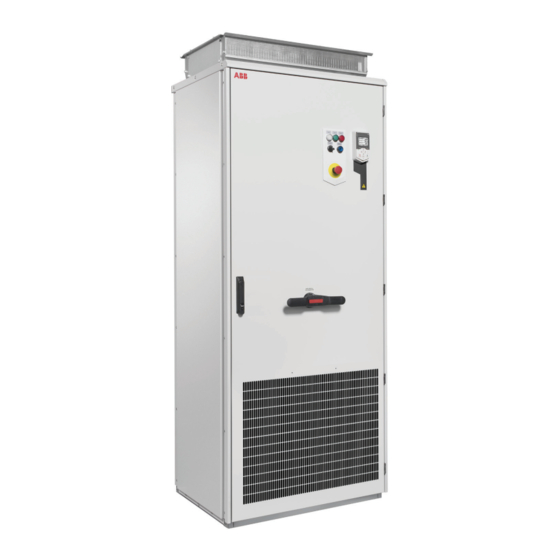
Operation principle and hardware description Contents of this chapter This chapter briefly describes the operation principle and construction of the drive. Product overview The ACS580-07 is an air-cooled cabinet-installed drive for controlling asynchronous AC induction motors and permanent magnet motors. -
Page 26: Single-Line Circuit Diagram Of The Drive
26 Operation principle and hardware description ■ Single-line circuit diagram of the drive R6 R7 R8…R11 In frames R6 and R7: Switch fuse or molded case circuit breaker (option +F289). In frames R8 to R11: Switch-disconnector or molded case circuit breaker (option +F289). Line contactor (option +F250) Auxiliary voltage transformer supplying 24 V and 230/115 V control voltage for, eg, cabinet fan(s), control devices and I/O extension adapter module. -
Page 27: General Information On The Cabinet Layout
Operation principle and hardware description 27 ■ General information on the cabinet layout „ „ IP21 IP42 UL Type 1 (option +B054) ■ Cabinet layout – R6 and R7 (bottom entry and exit of cables) The cabinet layout of frame R7 with dut/dt filter (option +E205) is shown below. Degree of protection IP42 (option +B054). - Page 28 28 Operation principle and hardware description Cabinet door closed Auxiliary voltage transformer T21 Cabinet door open Motor cable connection terminals Note: For drives with no du/dt filter (option +E205), the motor cables are connected to the drive module terminals. Cabinet door open, mounting plate and cabinet Input cable connection terminals shrouds removed Drive control panel...
-
Page 29: Cabinet Layout - R8 And R9 (Bottom Entry And Exit Of Cables)
Operation principle and hardware description 29 ■ Cabinet layout – R8 and R9 (bottom entry and exit of cables) The cabinet layout of frame R9 with du/dt filter (option +E205) is shown below. Degree of protection IP42 (option +B054). Frame R8 looks similar. Cabinet door closed Auxiliary voltage transformer T21 Cabinet door open... -
Page 30: Mounting Plate - R6 To R9
30 Operation principle and hardware description ■ Mounting plate – R6 to R9 The components and terminals on the mounting plate of frames R6 to R9 are shown below. The layout of frames R6 and R7 is similar. +G300 switch-disconnector and miniature circuit External main contactor control breaker for cabinet heater (option +G300) Emergency stop relay for options +Q951... - Page 31 Operation principle and hardware description 31 X251, X4, X6, X56, X53, X51, X55, X18 and X19: for internal use. X250 Terminals for X250 Auxiliary contacts of line contactor (option +F250) X289 Auxiliary contacts of molded case circuit breaker (op- tion +F289) X951 Push buttons for emergency stop option +Q951 or +Q963.
-
Page 32: Cabinet Layout - R10 And R11 (Bottom Entry And Exit Of Cables)
32 Operation principle and hardware description ■ Cabinet layout – R10 and R11 (bottom entry and exit of cables) Cabinet door closed Main switch-disconnector Cabinet door open AC fuses Gratings for cooling air out Line contactor (option +F250) Operating switch Lifting lugs Drive control panel Drive control unit... -
Page 33: Mounting Plate
Operation principle and hardware description 33 Cabinet door open, mounting plates and cabinet Input cable connection terminals shrouds removed Power and control cable entries Drive module Motor cable connection terminals Auxiliary voltage transformer T21 Mounting plate The components and terminals on the mounting plate of frames R10 and R11 are shown below. - Page 34 34 Operation principle and hardware description Drive control unit X289 Indication of the status of the molded case circuit breaker (option +F289) Emergency stop relay for options +Q951 X300 Connection terminals for cabinet heater and +Q963 (option +G300) Q95, F95 Switch-disconnector and miniature circuit X951 Connection of external emergency stop...
-
Page 35: Cooling Air Flow
Operation principle and hardware description 35 X251, X4, X6, X56, X53, X51, X55, X18 and X19: for internal use. ■ Cooling air flow The figure below shows cooling air flow in frames R6 to R9 (side view) and in frames R10 and R11 (front view). - Page 36 „ 36 Operation principle and hardware description SLOT 1 SLOT 2 M 3 ~ Option slot 1 for optional fieldbus adapter modules Option slot 2 for optional I/O extension modules Embedded fieldbus connector Panel port I/O terminal blocks. See section Layout (page 93) and section Default I/O connection diagram (page...
-
Page 37: Door Switches And Lights
Operation principle and hardware description 37 ■ Door switches and lights „ Label in English Label in local Description language READY Ready pilot light (option +G327) Run pilot light (option+G328) FAULT Fault pilot light (option +G329) MAIN CONT. Operating switch with option +F250 OFF ON 0 Opens the main contactor (Q2) and disables starting of the drive 1 Closes the main contactor (Q2) -
Page 38: Control By Pc Tools
56). Descriptions of cabinet options Note: All options are not available for all drive types or do not coexist with certain other options. Check actual availability with ABB. ■ Degree of protection Definitions According to IEC/EN 60529, the degree of protection is indicated by an IP code where the first numeral means protection against ingress of solid foreign objects, and the second numeral protection against ingress of water. -
Page 39: Ip21
Operation principle and hardware description 39 IP code The equipment is protected … First numeral Second numeral IP21 against ingress of solid foreign objects >12.5 mm against dripping (vertically falling drops) IP42 against ingress of solid foreign objects > 1 mm against dripping (15°... -
Page 40: Du/Dt Filter (Option +E205)
40 Operation principle and hardware description ■ du/dt filter (option +E205) The du/dt filter protects the motor insulating system by reducing the voltage rise speed at the motor terminals. The filter also protects the motor bearings by reducing the bearing currents. -
Page 41: Type Designation Label
Type designation key The type designation contains information on the specifications and configuration of the drive. The first digits from left express the basic configuration (eg, ACS580-07-0640A-4). The optional selections are given thereafter, separated by plus signs, eg, +B055. The main selections are described below. - Page 42 42 Operation principle and hardware description Code Description Basic codes ACS580 Product series When no options are selected: cabinet-installed drive, IP21, main switch, AC fuses, ACS-AP-S assistant control panel, for frames R6 to R9 EMC filtering for first environment TN grounded systems (category C2), for frames R10 and R11 EMC filtering for second environment TN grounded systems (category C3), input choke, common mode filter in frames R10 and R11, coated boards, ACS580 standard control program, EIA/R5-485 fieldbus connector, Safe torque off function, bottom entry...
- Page 43 Operation principle and hardware description 43 Code Description Cabinet options G300 Cabinet heater (external supply). See Cabinet heater with external supply (option +G300) (page 40). G327 Ready pilot light, white G328 Run pilot light, green G329 Fault pilot light, red Cabling H351 Top entry of cables.
- Page 44 44 Operation principle and hardware description Code Description Q951 Emergency stop of Category 0 with opening the main contactor or breaker Q963 Emergency Stop, Category 0 without opening main contactor with safety relay Q971 ATEX-certified Safe disconnection function, EX II (2) GD. Requires +L537 Printed documentation (manuals, dimensional drawings, circuit diagrams and manual language).
-
Page 45: Mechanical Installation
Mechanical installation 45 Mechanical installation Contents of this chapter This chapter describes the mechanical installation procedure of the drive. Examining the installation site Examine the installation site: • The installation site is sufficiently ventilated or cooled to transfer away the drive losses. See the technical data. -
Page 46: Necessary Tools
46 Mechanical installation Do not install the drive on an elevated platform or a recess. The module extraction/installation ramp included with the drive is only suitable for a height difference of 50 mm maximum (ie. the standard plinth height of the drive). Necessary tools The tools required for moving the unit to its final position, fastening it to the floor and wall and tightening the connections are listed below:... - Page 47 Mechanical installation 47 Vertical package: 1088 Lifting the transport package with slings. Lifting points Lifting the transport package with forklift...
-
Page 48: Unpacking The Transport Package
48 Mechanical installation „ ■ Unpacking the transport package This drawing shows the layout of the horizontal transport package. Bracket for attaching the drive to the wooden Timber pallet Cardboard packing hood Drive cabinet Wooden pallet Unpack the horizontal transport package as follows: 1. -
Page 49: Lifting The Cabinet
Mechanical installation 49 • drive cabinet • option modules (if ordered) installed onto the control unit at the factory • appropriate drive and option module manuals • delivery documents. Check that there are no signs of damage. Before attempting installation and operation, check the information on the type designation labels of the drive to verify that the delivery is of the correct type. -
Page 50: Moving The Cabinet After Unpacking
50 Mechanical installation „ Lift the cabinet to its position. Maximum allowed angle of the lifting slings is 20° (10° for frames R10 and R11, IP54). ° Max. 10 ° Max. 20 R10, R11 IP54 „ ■ Moving the cabinet after unpacking Move drive cabinet carefully in the upright position. -
Page 51: Final Placement
Mechanical installation 51 Final placement Move the cabinet into its final position with an iron bar. Place a wooden piece at the bottom edge of the cabinet in order not to damage the cabinet frame with the iron bar. Attaching the cabinet to the floor and wall or roof „... -
Page 52: Attaching Methods
52 Mechanical installation Note 1: Make height adjustments before attaching the cabinet with metal shims between the cabinet bottom and the floor. Note 2: If you remove the lifting eyes, attach the bolts back to retain the degree of protection of the cabinet. -
Page 53: Alternative 2 - Using The Holes Inside The Cabinet
■ Arc welding ABB does not recommend attaching the cabinet by arc welding. However, if arc welding is the only option, connect the return conductor of the welding equipment to the cabinet frame at the bottom within 0.5 meters (1’6”) of the welding point. - Page 54 54 Mechanical installation connected improperly, the welding circuit can damage electronic circuits in the cabinet. WARNING! Do not inhale the welding fumes.
-
Page 55: Guidelines For Planning The Electrical Installation
The installation must always be designed and made according to applicable local laws and regulations. ABB does not assume any liability whatsoever for any installation which breaches the local laws and/or other regulations. Furthermore, if the recommendations given by ABB are not followed, the drive may experience problems that the warranty does not cover. -
Page 56: Examining The Compatibility Of The Motor And Drive
Examining the compatibility of the motor and drive Use an asynchronous AC induction motors, permanent magnet synchronous motors, AC induction servomotors or ABB synchronous reluctance motors (SynRM motors) with the drive. Select the motor size and drive type from the rating tables on basis of the AC line voltage and motor load. - Page 57 Guidelines for planning the electrical installation 57 This table shows the requirements when an ABB motor is in use. Motor Nominal AC supply Requirement for type voltage Motor insula- ABB du/dt and common mode filters, insulated N-end tion system motor bearings <...
- Page 58 58 Guidelines for planning the electrical installation This table shows the requirements when a non-ABB motor is in use. Motor Nominal AC supply Requirement for type voltage Motor insula- ABB du/dt and common mode filters, insulated N-end tion system motor bearings <...
-
Page 59: Availability Of Du/Dt Filter And Common Mode Filter By Drive Type
The rated output power of high-output motors is higher than what is stated for the particular frame size in EN 50347 (2001). If you plan to use a non-ABB high-output motor or an IP23 motor, consider these additional requirements for protecting the motor insulation and bearings in drive systems: •... -
Page 60: Additional Data For Calculating The Rise Time And The Peak Line-To-Line Voltage
60 Guidelines for planning the electrical installation Nominal AC supply Requirement for voltage Motor insulation system ABB du/dt and common mode filters, insulated N- end motor bearings < 100 kW or frame 100 kW < P < 350 kW or size <... -
Page 61: Selecting The Power Cables
Guidelines for planning the electrical installation 61 Û du/dt ------------ - (1/Ps) l (m) du/dt ------------ - (1/Ps) Û l (m) Drive with du/dt filter Drive without du/dt filter Motor cable length Û Relative peak line-to-line voltage (du/dt)/U Relative du/dt value Selecting the power cables ■... -
Page 62: Typical Power Cable Sizes
When continuous metal conduit is employed, shielded cable is not required. The conduit must have bonding at both ends. A four-conductor system is allowed for input cabling, but ABB recommends shielded symmetrical cable. Compared to a four-conductor system, the use of symmetrical shielded cable reduces electromagnetic emission of the whole drive system as well as the stress on motor insulation, bearing currents and wear. -
Page 63: Power Cable Types For Limited Use
Guidelines for planning the electrical installation 63 Symmetrical shielded cable with three phase conductors and a concentric PE conductor as shield. A separate PE conductor is required if the shield does not meet the require- ments of IEC 61800-5-1, see section Motor cable shield (page 63). -
Page 64: Selecting The Control Cables
■ Relay cable type The cable type with braided metallic screen (for example ÖLFLEX by LAPPKABEL, Germany) has been tested and approved by ABB. ■ Control panel cable length and type In remote use, the cable connecting the control panel to the drive must not be longer than three meters (10 ft). -
Page 65: Separate Control Cable Ducts
Guidelines for planning the electrical installation 65 min 300 mm (12 in.) 90° min 500 mm (20 in.) min 200 mm (8 in.) Drive Motor cable Input power cable Power cable Control cable ■ Separate control cable ducts Lead 24 V and 230 V (120 V) control cables in separate ducts unless the 24 V cable is insulated for 230 V (120 V) or insulated with an insulation sleeving for 230 V (120 V). -
Page 66: Protecting The Motor And Motor Cable In Short-Circuits
66 Guidelines for planning the electrical installation The drive is equipped with internal AC fuses as standard. In case of a short-circuit inside the drive, the AC fuses protect the drive, restrict drive damage, and prevent damage to adjoining equipment. ■... -
Page 67: Implementing The Emergency Stop Function
See the user’s manual for the wiring, start-up and operation instructions. Option User’s manual Manual code (English) code +Q951 Emergency stop, stop category 0 (option +Q951) for ACS580-07, 3AXD50000171828 ACH580-07 and ACQ580-07 drives user's manual +Q963 Emergency Stop, Category 0 (option +Q963) without opening main 3AXD50000171835... -
Page 68: Supplying Power For The Auxiliary Circuits
Implementing a safety switch between the drive and the motor ABB recommends to install a safety switch between the permanent magnet synchronous motor and the drive output. The switch is needed to isolate the motor during any maintenance work on the drive. -
Page 69: Implementing A Bypass Connection
Inductive loads (relays, contactors, motors) cause voltage transients when switched off. ABB highly recommends to equip inductive loads with noise attenuating circuits (varistors, RC filters [AC] or diodes [DC]) in order to minimize the EMC emission at switch-off. If not suppressed, the disturbances can connect capacitively or inductively to other conductors in the control cable and form a risk of malfunction in other parts of the system. -
Page 70: Implementing A Motor Temperature Sensor Connection
70 Guidelines for planning the electrical installation Implementing a motor temperature sensor connection WARNING! IEC 60664 requires double or reinforced insulation between live parts and the surface of accessible parts of electrical equipment which are either non-conductive or conductive but not connected to the protective earth. To connect a motor temperature sensor and other similar components to the drive, you have four alternatives: 1. -
Page 71: Electrical Installation
Electrical installation 71 Electrical installation Contents of this chapter This chapter gives instructions on the wiring the drive. Warnings WARNING! If you are not a qualified electrician do not do the installation work described in this chapter. Obey the instructions in chapter Safety instructions. -
Page 72: Layout Of The Cable Entries (Frames R6 To R9)
72 Electrical installation Layout of the cable entries (frames R6 to R9) The layout of the input and motor cable connection terminals of frame R9 without du/dt filter (option +E205) is shown below. The shrouds in front of the terminals are removed. The layout is similar for the other frame sizes. -
Page 73: Layout Of The Cable Entries (Frames R10 And R11)
Electrical installation 73 Layout of the cable entries (frames R10 and R11) The layout of the input and motor cable connection terminals of frame R10 is shown below. The shrouds in front of the terminals are removed. The layout is similar for frame R11. L1, L2, L3 Input power cable terminals U2, V2, W2... -
Page 74: Connecting The Power Cables
74 Electrical installation Connecting the power cables ■ Connection diagram... - Page 75 Electrical installation 75 „ ACS580-07 T1/ T2/ T3/ (PE) (PE) Use a separate grounding PE cable (1a) or a cable with a separate PE conductor (1b) if the conductivity of the shield does not meet the requirements for the PE conductor.
-
Page 76: Checking The Insulation Of The Drive
Earth conductor using a measuring voltage of 1000 V DC. The insulation resistance of an ABB motor must exceed 100 Mohm (reference value at 25 °C or 77 °F). For the insulation resistance of other motors, consult the manufacturer’s instructions. -
Page 77: Connection Procedure (Iec, Frames R6 To R9)
Electrical installation 77 „ ■ Connection procedure (IEC, frames R6 to R9) 1. Do the steps in section Electrical safety precautions (page 16) before you start the work. 2. Open the cabinet door. 3. For drives without option +E205: To remove the mounting plate, undo the mounting screws and unplug the connectors on top of it: •... - Page 78 78 Electrical installation 7. Prepare the ends of the cables. WARNING! Apply grease to stripped aluminum conductors before attaching them to non-coated aluminum cable lugs. Obey the grease manufacturer’s instructions. Aluminum-aluminum contact can cause oxidation in the contact surfaces. 8. If fire insulation is used, make an opening in the mineral wool sheet according to the diameter of the cable.
- Page 79 12. Seal the slot between the cable and mineral wool sheet (if used) with sealing compound (eg, CSD-F, ABB brand name DXXT-11, code 35080082). 13. Connect the twisted shields of the motor cables to the ground bar and the phase conductors to the U2, V2 and W2 terminals of the drive module.
-
Page 80: Connection Procedure (Iec, Frames R10 And R11)
80 Electrical installation 15. Tighten the power cable screws to the torque given in Terminal and entry data for the power cables (page 160). 16. Reinstall the shrouds and mounting plate. ■ Connection procedure (IEC, frames R10 and R11) 1. Do the steps in section Electrical safety precautions (page 16) before you start the work. - Page 81 Electrical installation 81 • With top entry (option +H351) and bottom exit: Undo the mounting screws and pull the shroud out.
- Page 82 82 Electrical installation • With top entry and top exit (options +H351 and +H353): Remove the shrouds and door fan (see Replacing the door fan (frames R10 and R11) (page 119)). Undo the mounting screws and pull the shrouds out. 4.
- Page 83 Electrical installation 83 WARNING! Apply grease to stripped aluminum conductors before attaching them to non-coated aluminum cable lugs. Obey the grease manufacturer’s instructions. Aluminum-aluminum contact can cause oxidation in the contact surfaces. 7. If fire insulation is used, make an opening in the mineral wool sheet according to the diameter of the cable.
-
Page 84: Connecting The Control Cables
11. Seal the slot between the cable and mineral wool sheet (if used) with sealing compound (eg, CSD-F, ABB brand name DXXT-11, code 35080082). 12. Connect the twisted shields of the motor cables to the ground bar and the phase conductors to the U2, V2 and W2 terminals of the drive module. -
Page 85: Grounding The Outer Shields Of The Control Cables At The Cabinet Entry
Electrical installation 85 • Connecting external wiring to the control unit or optional I/O terminal block (page 88) • Connecting the emergency stop push buttons (options +Q951 and +Q963) (page 89) • Connecting the Safe torque off circuit (page 89) •... - Page 86 Note 2: If the outer surface of the shield is non-conductive: • Cut the shield at the midpoint of the bare part. Be careful not to cut the conductors or the grounding wire (if present). 86 Electrical installation • Turn the shield inside out to expose its conductive surface. •...
-
Page 87: Routing The Control Cables Inside The Cabinet
Electrical installation 87 ■ Routing the control cables inside the cabinet The route of the control cables is shown below in frame R9. The route is similar frames R6, R7 and R8. X504 (+L504) -
Page 88: Connecting External Wiring To The Control Unit Or Optional I/O Terminal Block
88 Electrical installation The route of the control cables for frames R10 and R11 is shown below. X504 (+L504) ■ Connecting external wiring to the control unit or optional I/O terminal block Note: Keep any signal wire pairs twisted as close to the terminals as possible. Twisting the wire with its return wire reduces disturbances caused by inductive coupling. -
Page 89: Connecting The Emergency Stop Push Buttons (Options +Q951 And +Q963)
Electrical installation 89 Leave the other ends of the control cable shields unconnected or ground them indirectly via a high-frequency capacitor with a few nanofarads, eg, 3.3 nF / 630 V. The shield can also be grounded directly at both ends if they are in the same ground line with no significant voltage drop between the end points. -
Page 90: Connecting External Power Supply Wires For The Cabinet Heater (Option +G300)
90 Electrical installation * Remove bridges 1–2 and 3–4 if there is an external Internal Customer X969 Safe torque off function connections connections STO OUT1 STO OUT1 STO IN1 STO IN1 STO IN2 STO IN2 STO OUT2 STO OUT2 STO INTERNAL „... -
Page 91: Connecting A Pc
Electrical installation 91 Connecting a PC A PC (with eg. the Drive composer PC tool) can be connected to the drive as follows: 1. Connect a control panel to the drive either by using an Ethernet (eg. CAT5E) networking cable, or by inserting the panel into the panel holder. WARNING! Do not connect the PC directly to the control panel connector of the control unit as this can cause damage. -
Page 92: Wiring The Optional Modules
92 Electrical installation 2. Tighten the mounting screw (CHASSIS) to 0.8 N·m. The screw tightens the connections and grounds the module. It is necessary for fulfilling the EMC requirements and for correct operation of the module. ■ Wiring the optional modules See the appropriate optional module manual or for I/O options chapter Optional I/O extension modules for specific installation and wiring instructions. -
Page 93: Control Unit
Control unit 93 Control unit Contents of this chapter This chapter contains the default I/O connection diagram, descriptions of the terminals and technical data for the drive control unit (CCU-24) Layout The layout of the external control connection terminals on the drive module control unit is shown below. - Page 94 94 Control unit SLOT 1 SLOT 1 Option slot 1 (fieldbus adapter modules) ANALOG IN/OUT 1...3 Analog input 1 1…3, AI1 Current/Voltage selection switch analog input 1 4…6, AI2 4...6 Analog input 2 7…9, AO1 Current/Voltage selection switch for analog input 2 10…12 7...9 Analog outputs...
-
Page 95: Default I/O Connection Diagram
Control unit 95 Default I/O connection diagram The default I/O connections of the ABB Standard macro are shown below. Reference voltage and analog inputs and outputs Signal cable shield (screen) Output frequency reference: 0…10 V 1…10 kohm AGND Analog input circuit common... -
Page 96: Option +E205 In Frames R10 And R11: Di6 Internal Overtemperature Supervision
96 Control unit 2. Total load capacity of the Auxiliary voltage output +24V (X2:10) is 6.0 W (250 mA / 24 V) minus the power taken by the option modules installed on the board. 3. In scalar control (default): See Menu - Primary settings - Start, stop, reference - Constant frequencies or parameter group 28 Frequency reference chain. -
Page 97: Power Supply Connections For Npn With Option +L504
Control unit 97 Internal +24 V power supply External +24 V power supply PNP connection (source) PNP connection (source) X503:1 X503:1 +24V +24V DGND DGND 0 V DC DCOM DCOM +24 V DC X504:18 X504:18 Power supply connections for NPN with option +L504 Internal and external +24 V power supply connections for NPN configuration are shown below. -
Page 98: Changing Internal Overtemperature Supervision From Di6 To Another Digital Input
98 Control unit Internal +24 V power supply External +24 V power supply NPN connection (sink) NPN connection (sink) +24V +24V DGND DGND +24 V DC DCOM DCOM 0 V DC Changing internal overtemperature supervision from DI6 to another digital input With option +E205 in frames R10 and R11, by default, digital input DI6 is used for the internal overtemperature supervision of the drive cabinet. -
Page 99: Npn Configuration For Digital Inputs (X2 & X3)
Control unit 99 Internal +24 V power supply External +24 V power supply PNP connection (source) PNP connection (source) X2 & X3 X2 & X3 +24V +24V DGND DGND 0 V DC DCOM DCOM +24 V DC WARNING! Do not connect the +24 V AC cable to the control unit ground when the control unit is powered from an external 24 V AC supply. -
Page 100: Connection Examples Of Two-Wire And Three-Wire Sensors To Analog Input (Ai2)
100 Control unit 8 AO2 Analog output 2. Default output 0…20 mA. 500 ohm Analog common ground. Internally connected to chassis 9 AGND through a 2 Mohm resistor. 8 AO2 Analog output 2. Default output 0…20 mA. 1 kohm 1 kohm Analog common ground. -
Page 101: Ai1 And Ai2 As Pt100, Pt1000, Ni1000, Kty83 And Kty84 Sensor Inputs (X1)
Control unit 101 "0" > kohm "1" < 1.5 kohm = 5 mA ■ AI1 and AI2 as Pt100, Pt1000, Ni1000, KTY83 and KTY84 sensor inputs (X1) One, two or three Pt100 sensors; one, two or three Pt1000 sensors; or one Ni1000, KTY83 or KTY84 sensor for motor temperature measurement can be connected between an analog input and output as shown below. -
Page 102: Technical Data
102 Control unit Remove the jumpers before connecting an external Safe torque off circuitry to the drive. See also chapter Safe torque off function (page 221). Note: Only 24 V DC can be used for STO. Only PNP input configuration can be used. Technical data External power supply Maximum power: 36 W, 1.50 A at 24 V AC/DC ±10% as standard... - Page 103 Control unit 103 Analog outputs AO1 and AO2 Current/voltage output mode for AO1 selected with a dip switch, see Connec- (Term. 7 and 8) tion for obtaining 0…10 V from analog output 2 (AO2) (page 99). Current output: 0…20 mA, R : <...
- Page 104 104 Control unit The terminals on the control board fulfill the Protective Extra Low Voltage (PELV) requirements (EN 50178): There is reinforced insulation between the user terminals which only accept ELV voltages and terminals that accept higher voltages (relay outputs). Note: There is functional insulation also between the individual relay outputs.
- Page 105 Control unit 105 Ground isolation diagram Slot 1 Slot 2 AGND +10V AGND AGND X2 & X3 +24V DGND DCOM X6, X7, X8 RO1C RO1A RO1B RO2C RO2A RO2B RO3C RO3A RO3B DGND OUT1 OUT2 SGND 24VAC/DC+in 24VAC/DC-in Ground Jumper installed at factory...
-
Page 107: Installation Checklist
If the drive will be connected to an IT (ungrounded) or a corner grounded TN network: The EMC filter of the drive has been disconnected. Contact your local ABB representative for instructions. There is an adequately sized protective earth (ground) conductor between the drive and the switchboard, and the conductor has been connected to appropriate terminal, and the terminal have been tightened. - Page 108 108 Installation checklist Check that … There is an adequately sized protective earth (ground) conductor between the motor and the drive, and the conductor has been connected to appropriate terminal, and the terminal have been tightened. (Pull on the conductors to check.). Proper grounding has also been measured according to the regula- tions.
-
Page 109: Start-Up
Start-up 109 Start-up Contents of this chapter This chapter contains the start-up procedure of the drive. The default device designations (if any) are given in brackets after the name, for example "main switch-disconnector (Q1)". The same device designations are also used in the circuit diagrams, typically. Start-up procedure Action Safety... - Page 110 110 Start-up Action Drives with main contactor (Q2, option +F250): Close the main contactor by turning the operating switch on the cabinet door from OFF into ON position. Perform the first start of the drive and motor. Stop the motor and drive. Drives with a fieldbus adapter module (optional): Set the fieldbus parameters.
-
Page 111: Fault Tracing
Fault tracing 111 Fault tracing Contents of this chapter This chapter describes the fault tracing possibilities of the drive. Warning and fault messages See the firmware manual for the descriptions, causes and remedies of the drive control program warning and fault messages. -
Page 113: Maintenance
(www.abb.com/drivesservices).For more information, consult your local ABB Service representative (www.abb.com/searchchannels). The maintenance and component replacement intervals are based on the assumption that the equipment is operated within the specified ratings and ambient conditions. ABB recommends annual drive inspections to ensure the highest reliability and optimum performance. -
Page 114: Recommended Annual Maintenance Actions By The User
114 Maintenance ■ Recommended annual maintenance actions by the user. Action Target IP42 air inlet and outlet meshes on the cabinet doors IP54 air filters on the cabinet doors Quality of supply voltage Spare parts Capacitor reforming, spare modules and spare capacitors Tightness of terminals Dustiness, corrosion or temperature Heat sink cleaning... -
Page 115: Cleaning The Air Inlet (Door) Meshes (Ip42 / Ul Type 1 Filtered)
Maintenance 115 3. Check the air inlet and outlet meshes/filters of the cabinet. Clean when necessary. For IP42 (UL Type 1 Filtered) drives: see section Cleaning the air inlet (door) meshes (IP42 / UL Type 1 Filtered) below. For IP54 (UL Type 12) drives: see section Cleaning the air inlet (door) meshes (IP42 / UL Type 1 Filtered). -
Page 116: Outlet (Roof) Filters (Ip54 / Ul Type 12)
116 Maintenance ■ Outlet (roof) filters (IP54 / UL Type 12) 1. Remove the front and back gratings of the fan cubicle by lifting them upwards 2. Remove the air filter mat. 3. Place the new filter mat in the grating. 4. -
Page 117: Fans
Reset the running time signal after a fan replacement. Replacement fans are available from ABB. Do not use other than ABB specified spare parts. ■ Replacing the door fan (frames R6 to R9) Applicability: For drives with option +F250, +L537, +B055, +Q951, +Q963, +Q971 or +G300. -
Page 118: Replacing The Cabinet Fan (Frames R6 To R9)
118 Maintenance ■ Replacing the cabinet fan (frames R6 to R9) Applicability: For drives without any of these options +F250, +L537, +B055, +Q951, +Q963, +Q971 and +G300 WARNING! Obey the instructions in chapter Safety instructions. If you ignore them, injury or death, or damage to the equipment can occur. -
Page 119: Replacing The Door Fan (Frames R10 And R11)
Maintenance 119 ■ Replacing the door fan (frames R10 and R11) WARNING! Obey the instructions in chapter Safety instructions. If you ignore them, injury or death, or damage to the equipment can occur. 1. Stop the drive and do the steps in section Electrical safety precautions (page 16) before you start the work. - Page 120 120 Maintenance...
-
Page 121: Replacing The Cabinet Fan (Frames R10 And R11, Ip54)
Maintenance 121 ■ Replacing the cabinet fan (frames R10 and R11, IP54) WARNING! Obey the instructions in chapter Safety instructions. If you ignore them, injury or death, or damage to the equipment can occur. 1. Stop the drive and do the steps in section Electrical safety precautions (page 16) before you start the work. -
Page 122: Replacing The Drive Module Main Fans (Frames R6 To R8)
122 Maintenance ■ Replacing the drive module main fans (frames R6 to R8) WARNING! Obey the instructions in chapter Safety instructions. If you ignore them, injury or death, or damage to the equipment can occur. 1. Stop the drive and do the steps in section Electrical safety precautions (page 16) before you start the work. -
Page 123: Replacing The Drive Module Main Fans (Frame R9)
Maintenance 123 10. Install the new fan in reverse order. 11. Reset the fan on-time counter in parameter group 5 of the drive control program. ■ Replacing the drive module main fans (frame R9) WARNING! Obey the instructions in chapter Safety instructions. -
Page 124: Replacing The Drive Module Main Fans (Frames R10 And R11)
124 Maintenance ■ Replacing the drive module main fans (frames R10 and R11) WARNING! Obey the instructions in chapter Safety instructions. If you ignore them, injury or death, or damage to the equipment can occur. 1. Stop the drive and do the steps in section Electrical safety precautions (page 16) before you start the work. -
Page 125: Replacing The Auxiliary Cooling Fan Of The Drive Module (Frames R6 To R9)
Maintenance 125 ■ Replacing the auxiliary cooling fan of the drive module (frames R6 to WARNING! Obey the instructions in chapter Safety instructions. If you ignore them, injury or death, or damage to the equipment can occur. 1. Stop the drive and do the steps in section Electrical safety precautions (page 16) before you start the work. -
Page 126: Replacing The Drive Module (Frames R6 To R9)
126 Maintenance Replacing the drive module (frames R6 to R9) This replacing procedure requires: preferably two persons, a set of screw drivers with extension bar and a torque wrench, chains for securing the module during the installation. The drawings below show a cabinet of frame size R7. The procedure is the same for the other frame sizes. - Page 127 Maintenance 127 Tap screw M6x16 T30 (hex) Torx M6x16 Torx M6x16 Torx M6x16 4. Unplug the wires connected to the mounting plate connectors (if present). 5. Remove the mounting plate (four screws). 6. Remove the shroud (two screws). 7. Remove the shroud on the power cable connection terminals.
- Page 128 128 Maintenance 8. Disconnect the option modules from the control unit. 9. For drives with additional I/O terminal block (option +L504), disconnect the upper terminals and remove any fastening. Move the wires aside before you lift the module out. Note: Mark the wires for reconnection!
- Page 129 Maintenance 129 10. For drives without additional I/O terminal block (option +L504), disconnect the customer-installed wires from the control unit. Note: Mark the wires for reconnection! 11. For drives with line contactor (option +F250), disconnect the input power cables from the output of the contactor.
- Page 130 130 Maintenance 13. Secure the drive module with chains from the lifting eyes. 14. Undo the mounting screws of the flange. 15. Slide the drive module forwards along the sliding bars. 16. Lift the module out of the cabinet with a lifting device.
- Page 131 Maintenance 131 17. Remove the flange.
- Page 132 132 Maintenance Combiscrew M6×25 T25 M6 nut, 6 N·m M6 nut, 6 N·m M6×10 T30, 6 N·m 18. Install the new module in reverse order.
-
Page 133: Replacing The Drive Module (Frames R10 And R11)
Maintenance 133 Replacing the drive module (frames R10 and R11) WARNING! Obey the instructions in chapter Safety instructions. If you ignore them, injury or death, or damage to the equipment can occur. This replacing procedure requires: preferably two persons, installation ramp, a set of screw drivers and a torque wrench with an extension bar of 500 mm (20 in), chains for securing the module during the installation. - Page 134 134 Maintenance...
- Page 135 Maintenance 135...
- Page 136 136 Maintenance 7. Disconnect the drive module input busbars with a torque wrench withn an extension bar of 500 mm (20 in). Combi screw M12, 70 N·m (52 lbf·ft). 8. Disconnect the drive module output busbars. M12, 70 N·m (52 lbf·ft).
- Page 137 Maintenance 137 9. Remove the shroud. Undo the screws that attach the drive module to the cabinet at the top and behind the front support legs.
- Page 138 138 Maintenance 10. Attach the extraction ramp to the cabinet base with two screws. 11. Attach the drive module lifting lugs to the cabinet lifting lug with chains. 12. Pull the drive module carefully out of the cabinet preferably with help from another person.
-
Page 139: Replacing The Drive Module (Frames R10 And R11, Ip54)
Maintenance 139 13. Install the new module in reverse order. Replacing the drive module (frames R10 and R11, IP54) WARNING! Obey the instructions in chapter Safety instructions. If you ignore them, injury or death, or damage to the equipment can occur. This replacing procedure requires: preferably two persons, installation ramp, a set of screw drivers and a torque wrench with an extension bar of 500 mm (20 in), chains for securing the module during the installation. - Page 140 140 Maintenance...
- Page 141 Maintenance 141...
- Page 142 142 Maintenance 7. Disconnect the drive module input busbars with a torque wrench withn an extension bar of 500 mm (20 in). Combi screw M12, 70 N·m (52 lbf·ft). 8. Disconnect the drive module output busbars. M12, 70 N·m (52 lbf·ft).
- Page 143 Maintenance 143 9. Remove the shroud. Undo the screws that attach the drive module to the cabinet at the top and behind the front support legs.
- Page 144 144 Maintenance 10. Attach the extraction ramp to the cabinet base with two screws. 11. Attach the drive module lifting lugs to the cabinet lifting lug with chains. 12. Pull the drive module carefully out of the cabinet preferably with help from another person.
-
Page 145: Capacitors
Capacitor failure is usually followed by damage to the unit and an input cable fuse failure, or a fault trip. Contact ABB if capacitor failure is suspected. Replacements are available from ABB. Do not use other than ABB specified spare parts. -
Page 146: Replacing Ac Fuses
146 Maintenance 4. Replace the fuses with the fuse handle which is in the cabinet. 5. Reinstall the shrouding removed earlier and close the cabinet door. ■ Replacing AC fuses WARNING! Obey the instructions in chapter Safety instructions. If you ignore them, injury or death, or damage to the equipment can occur. -
Page 147: Replacing The Battery In The Assistant Control Panel
Maintenance 147 ■ Replacing the battery in the assistant control panel A battery is only used in assistant control panels that have the clock function. The battery keeps the clock operating during power interruptions. The expected life for the battery is greater than ten years. Note: The battery is NOT required for any control panel or drive functions, except the clock. -
Page 149: Technical Data
The nominal ratings for the drives with 50 Hz and 60 Hz supply are given below. The symbols are described in section Definitions (page 151). IEC RATINGS Drive type Frame Input Output ratings ACS580-07- size rating No-overload use Light-overload Heavy-overload = 400 V 0145A-4 0169A-4... -
Page 150: Nec Ratings
150 Technical data IEC RATINGS Drive type Frame Input Output ratings ACS580-07- size rating No-overload use Light-overload Heavy-overload 0650A-4 0725A-4 1020 0820A-4 1020 0880A-4 1100 725*** 3AXD10000451709 NEMA RATINGS Drive type Frame Input rat- Max. cur- App. Output ratings ACS580-07-... -
Page 151: Definitions
Note 2: To achieve the rated motor power given in the table, the rated current of the drive must be higher than or equal to the rated motor current. The DriveSize dimensioning tool available from ABB is recommended for selecting the drive, motor and gear combination. -
Page 152: Drive Types Acs580-0414A-4 And Acs580-0430A-4
„ „ 152 Technical data 1.00 0.90 0.80 +40 °C +50 °C +104 °F +122 °F For example: Temperature Derated current 40 ºC (104 ºF) 45 ºC (113 ºF) 0.95 · I 0.95 · I 50 ºC (122 ºF) 0.90 · I 0.90 ·... -
Page 153: Deratings For Special Settings In The Drive Control Program
Technical data 153 If ambient temperature is below +40 °C (+104 .°F), the derating can be reduced by 1.5% for every 1 °C reduction in temperature. Curves with derating factors from 1.00 to 0.80 are shown below. For a more accurate derating, use the DriveSize PC tool. A few altitude derating curves are shown below. -
Page 154: Fuses (Iec)
Changing the value of parameter 97.01 Switching frequency reference does not require derating. Fuses (IEC) The standard drive is equipped with aR fuses listed below. Drive type Input cur- Ultrarapid (aR) fuses (one fuse per phase) ACS580-07- rent Type Type Size (Buss- (Mersen) - Page 155 Technical data 155 Drive type Input Fuse (one fuse per phase) ACS580-07- current Type Type Type with op- Size class / tion +F289 (op- (Bussmann) (Mersen) Size tion +F289) = 480 V - NEMA types 0145A-4 DFJ-250 B235889A (HSJ 170M3416...
-
Page 156: Fuses For Branch Circuit Protection
156 Technical data Drive type Input current Fuse (one fuse per phase) with option +F289 ACS580-07- Manufacturer Type Size = 480 V 0145A-4 Bussmann 170M3416 0169A-4 Bussmann 170M3416 0206A-4 Bussmann 170M4410 0246A-4 Bussmann 170M5408 0293A-4 Bussmann 170M5410 0363A-4 Bussmann 170M6410... -
Page 157: Dimensions And Weights
Technical data 157 Drive type Input Fuse (one fuse per phase) NEC type current ACS580-07- Manufacturer Type class 0725A-4 Ferraz A4BY800 0820A-4 Ferraz A4BY900 0880A-4 1000 Ferraz A4BY1000 Note 1: See also Implementing the emergency stop function (page 67). Note 2: Fuses with higher current rating than the recommended ones must not be used. -
Page 158: Maximum Allowed Plinth Height For The Extraction/Installation Ramp
For the cable sizes accepted by the drive cabinet cable entries and connection terminals, see Terminal and entry data for the power cables (page 160). Drive type ACS580-07- Frame size Cu cable type Al cable type... -
Page 159: Losses, Cooling Data And Noise
Technical data 159 Drive type ACS580-07- Frame size Cu cable type Al cable type Cu cable type AWG/kcmil per phase 0240A-4 2x(3x70) 2x(3x95) 2x2/0 0260A-4 2x(3x95) 2x(3x120) 2x3/0 0361A-4 2x(3x120) 2x(3x185) 2x250 MCM 0414A-4 2x(3x150) 2x(3x240) 2x300 MCM The cable sizing is based on max. 9 cables laid on a cable ladder side by side, three ladder type trays one on top of the other, ambient temperature 30 °C, PVC insulation, surface temperature 70 °C (EN 60204-1and IEC 60364-5-52/2001). -
Page 160: Terminal And Entry Data For The Power Cables
160 Technical data Terminal and entry data for the power cables There are two (in frames R6 to R9) or four (in frames R10 and R11) 60 mm (2.36 in) diameter holes in the entry plate for the input power cables and two (in frames R6 to R9) or four (in frames R10 and R11) 60 mm (2.36 in) diameter holes for the motor cables. -
Page 161: Us - With Option +E205
Technical data 161 Frame L1, L2, L3 T1/U2, T2/V2, T3/W2 PE (grounding) size Max. wire Bolt size Tighten- Min. wire Max. wire Tighten- Bolt size Tighten- size ing torque size size ing torque ing torque lbf·ft lbf·ft lbf·ft 3×300 M10 (3/8") 22.1 3×300 22.1... -
Page 162: Connection Drawings
162 Technical data Connection drawings „ Frame R6: Input and motor cable terminal dimensions (bottom entry and exit, switch fuse OS250) DET A... - Page 163 Technical data 163 Frame R6: Input and motor cable terminal dimensions (bottom entry and exit, switch fuse OS400) DET A...
- Page 164 164 Technical data Frame R6: Input and motor cable terminal dimensions (option +F289) DET A...
- Page 165 Technical data 165 Frames R6 and R7: Input and motor cable terminal dimensions (bottom entry and exit, switch fuse OS250, du/dt filter [option +E205])
- Page 166 166 Technical data Frames R6 and R7: Input and motor cable terminal dimensions (bottom entry and exit, switch fuse OS400, du/dt filter [option +E205])
- Page 167 Technical data 167 Frames R6 and R7: Input and motor cable terminal dimensions (bottom entry and exit, options +F289 and +E205)
- Page 168 168 Technical data Frame R7: Input and motor cable terminal dimensions (bottom entry and exit, switch fuse OS250) DET A...
- Page 169 Technical data 169 Frame R7: Input and motor cable terminal dimensions (bottom entry and exit, switch fuse OS400) DET A...
- Page 170 170 Technical data Frame R7: Input and motor cable terminal dimensions (bottom entry and exit, option +F289)
- Page 171 Technical data 171 Frames R6 and R7: Input and motor cable terminal dimensions (top entry and exit, options +H351 and +H353)
- Page 172 172 Technical data Frame R8: Input and motor cable terminal dimensions (bottom entry and exit, switch-disconnector OT400) DET A...
- Page 173 Technical data 173 Frame R8: Input and motor cable terminal dimensions (bottom entry and exit, switch-disconnector OT400, du/dt filter [option +E205])
- Page 174 174 Technical data Frame R8: Input and motor cable terminal dimensions (bottom entry and exit, option +F289)
- Page 175 Technical data 175 Frame R9: Input and motor cable terminal dimensions (bottom entry and exit, switch-disconnector OT630) DET A...
- Page 176 176 Technical data Frame R9: Input and motor cable terminal dimensions (bottom entry and exit, switch-disconnector OT630, du/dt filter [option +E205])
- Page 177 Technical data 177 Frames R8 and R9: Input and motor cable terminal dimensions (top entry and exit, options +H351 and +H353)
- Page 178 178 Technical data Frames R8 and R9: Input and motor cable terminal dimensions (bottom entry and exit, options +F289 and +E205)
- Page 179 Technical data 179 Frame R9: Input and motor cable terminal dimensions (option +F289)
- Page 180 180 Technical data Frame R10: Input and motor cable terminal dimensions (bottom entry and exit)
- Page 181 Technical data 181 Frame R10: Input and motor cable terminal dimensions (bottom entry and exit, option +E205)
- Page 182 182 Technical data Frame R10: Input and motor cable terminal dimensions (top entry and exit)
- Page 183 Technical data 183 Frame R10: Input and motor cable terminal dimensions (top entry and exit, option +F289)
- Page 184 184 Technical data Frame R11: Input and motor cable terminal dimensions (bottom entry and exit)
- Page 185 Technical data 185 Frame R11: Input and motor cable terminal dimensions (bottom entry and exit, option +E205)
- Page 186 186 Technical data Frame R11: Input and motor cable terminal dimensions (top entry and exit)
- Page 187 Technical data 187 Frame R11: Input and motor cable terminal dimensions (top entry and exit, option +F289)
-
Page 188: Terminal And Connection Data For Auxiliary Control Circuits
188 Technical data Terminal and connection data for auxiliary control circuits Maximum acceptable voltage and current values and wire sizes in terminal blocks are given below. Terminal block Maximum acceptable voltage and current values and wire sizes X250 230V AC / 24V DC, 2A •... -
Page 189: Electrical Power Network Specification
Technical data 189 Electrical power network specification Voltage (U ACS580-07-xxxxx-4 drives: 380…480 VAC 3-phase ±10%. This is indicated in the type designation label as typical input voltage levels 3~400/480 V AC. Network type TN (grounded) and IT (ungrounded) systems Short-circuit withstand... -
Page 190: Protection Classes
190 Technical data Protection classes Degrees of protection IP21 (standard), IP42 (optional), IP54 (optional) (IEC/EN 60529) Enclosure types (UL50) UL Type 1 (standard), UL Type 1 (option +B054), UL Type 12 (option +B055). For indoor use only. Overvoltage category III, except for auxiliary power connections (fan, control, heating, lighting, cooling (IEC/EN 60664-1) unit pump etc) which are category II. -
Page 191: Ambient Conditions
Installation site altitude 0 to 2000 m (6561 ft) above sea level. For alti- tudes over 2000 m, con- tact ABB. Output derated above 1000 m (3281 ft). See section Output derating Air temperature -0 to +50 °C (32 to 122... -
Page 192: Auxiliary Circuit Power Consumption
80 micrometers) on visible surfaces, color RAL 7035 and RAL 9017. Busbars Tin-plated copper Air filters of IP54 drives Inlet (door): airComp 300-50 240 mm x 286 mm (ABB code 3AXD50000037880) Fire safety of materials Insulating materials and non-metallic items mostly self-extinctive (IEC 60332-1) -
Page 193: Applicable Standards
IEC 62635 guidelines. To aid recycling, plastic parts are marked with an appropriate identification code. Contact your local ABB distributor for further information on environmental aspects and recycling instructions for professional recyclers. End of life treatment must follow international and local regulations. -
Page 194: Compliance With The European Low Voltage Directive
194 Technical data ■ Compliance with the European Low Voltage Directive The compliance with the European Low Voltage Directive has been verified according to standard EN 61800-5-1. ■ Compliance with the European EMC Directive The EMC Directive defines the requirements for immunity and emissions of electrical equipment used within the European Union. -
Page 195: Declaration Of Conformity
Technical data 195 Declaration of Conformity... - Page 196 196 Technical data...
-
Page 197: Compliance With The En 61800-3:2004
Technical data 197 ■ Compliance with the EN 61800-3:2004 Definitions EMC stands for Electromagnetic Compatibility. It is the ability of electrical/electronic equipment to operate without problems within an electromagnetic environment. Likewise, the equipment must not disturb or interfere with any other product or system within its locality. First environment includes establishments connected to a low-voltage network which supplies buildings used for domestic purposes. -
Page 198: Ul Marking
Equipment (victim) 2. An EMC plan for preventing disturbances is drawn up for the installation. A template is available from the local ABB representative. 3. The motor and control cables are selected as specified in the hardware manual. 4. The drive is installed according to the instructions given in the hardware manual. -
Page 199: Rcm Marking
Technical data 199 in this chapter. The ampere rating is based on tests done according to the appropriate UL standard. • The cables located within the motor circuit must be rated for at least 75 °C (167 °F) in UL-compliant installations. •... -
Page 200: Disclaimers
ABB and its affiliates are not liable for damages and/or losses related to such security breaches, any unauthorized... -
Page 201: Dimension Drawings
Dimension drawings 201 Dimension drawings Example dimension drawings are shown below. -
Page 202: Frames R6 And R7 (Ip21, Ul Type 1)
202 Dimension drawings Frames R6 and R7 (IP21, UL Type 1) -
Page 203: Frames R6 And R7 (+B054: Ip42, Ul Type 1)
Dimension drawings 203 Frames R6 and R7 (+B054: IP42, UL Type 1) -
Page 204: Frames R6 And R7 (+B055: Ip54, Ul Type 12)
204 Dimension drawings Frames R6 and R7 (+B055: IP54, UL Type 12) -
Page 205: Frames R6 And R7 (+H351 And +H353: Top Entry And Exit)
Dimension drawings 205 Frames R6 and R7 (+H351 and +H353: top entry and exit) -
Page 206: Frames R6 And R7 (+F289)
206 Dimension drawings Frames R6 and R7 (+F289) -
Page 207: Frames R6 And R7 (+F289, +H351, +H353)
Dimension drawings 207 Frames R6 and R7 (+F289, +H351, +H353) -
Page 208: Frames R8 And R9 (Ip21)
208 Dimension drawings Frames R8 and R9 (IP21) -
Page 209: Frames R8 And R9 (+B054: Ip42, Ul Type 1)
Dimension drawings 209 Frames R8 and R9 (+B054: IP42, UL Type 1) -
Page 210: Frames R8 And R9 (+B055: Ip54, Ul Type 12)
210 Dimension drawings Frames R8 and R9 (+B055: IP54, UL Type 12) -
Page 211: Frames R8 And R9 (+H351 And +H353: Top Entry And Exit)
Dimension drawings 211 Frames R8 and R9 (+H351 and +H353: top entry and exit) -
Page 212: Frames R8 And R9 (+F289)
212 Dimension drawings Frames R8 and R9 (+F289) -
Page 213: Frames R8 And R9 (+F289, +H351, +H353)
Dimension drawings 213 Frames R8 and R9 (+F289, +H351, +H353) -
Page 214: Frames R10 And R11 (Ip21)
214 Dimension drawings Frames R10 and R11 (IP21) -
Page 215: Frames R10 And R11 (+B054: Ip42, Ul Type 1)
Dimension drawings 215 Frames R10 and R11 (+B054: IP42, UL Type 1) -
Page 216: Frames R10 And R11 (+B055: Ip54, Ul Type 12)
216 Dimension drawings Frames R10 and R11 (+B055: IP54, UL Type 12) -
Page 217: Frames R10 And R11 (+F289)
Dimension drawings 217 Frames R10 and R11 (+F289) -
Page 218: Frames R10 And R11 (+H351, +H353)
218 Dimension drawings Frames R10 and R11 (+H351, +H353) -
Page 219: Frames R10 And R11 (+B054: Ip42, Ul Type 1, +H351, +H353)
Dimension drawings 219 Frames R10 and R11 (+B054: IP42, UL type 1, +H351, +H353) -
Page 220: Frames R10 And R11 (+B055: Ip54, Ul Type 12, +H351, +H353)
220 Dimension drawings Frames R10 and R11 (+B055: IP54, UL type 12, +H351, +H353) -
Page 221: Safe Torque Off Function
Safe torque off function 221 Safe torque off function Contents of this chapter This chapter describes the Safe torque off function of the drive and gives instructions for its use. Description The Safe torque off function can be used, for example, to construct safety or supervision circuits that stop the drive in case of danger (such as an emergency stop circuit). -
Page 222: Compliance With The European Machinery Directive
222 Safe torque off function Standard Name IEC 61508-1:2010 Functional safety of electrical/electronic/programmable electronic safety-re- lated systems – Part 1: General requirements IEC 61508-2:2010 Functional safety of electrical/electronic/programmable electronic safety-re- lated systems – Part 2: Requirements for electrical/electronic/programmable electronic safety-related systems IEC 61511-1:2016 Functional safety –... -
Page 223: Grounding Of Protective Shields
Safe torque off function 223 Maximum cable lengths: • 300 m (984 ft) between activation switch (K) and drive control unit • 60 m (200 ft) between multiple drives • 60 m (200 ft) between external power supply and first drive. Note that the voltage at the INx terminals of each drive must be at least 13 V DC to be interpreted as “1”. -
Page 224: Single-Channel Connection
224 Safe torque off function Single-channel connection Drive Control unit OUT1 + 24 V DC OUT2 + 24 V DC SGND Control logic UDC+ T1/U, T2/V, T3/W UDC– „... -
Page 225: Single Drive (External +24 V Dc Power Supply)
Safe torque off function 225 ■ Single drive (external +24 V DC power supply) „ Drive 24 V DC Control unit OUT1 + 24 V DC OUT2 + 24 V DC SGND Control logic UDC+ T1/U, T2/V, T3/W UDC– „ ■... - Page 226 226 Safe torque off function Drive +24 V DC external Safe PLC power supply OUT1 OUT2 36 SGND Safety relay...
-
Page 227: Multiple Drives (Internal Power Supply)
Safe torque off function 227 „ ■ Multiple drives (internal power supply) Drive Control unit OUT1 + 24 V DC OUT2 + 24 V DC SGND Drive Control unit OUT1 + 24 V DC OUT2 + 24 V DC SGND Drive Control unit OUT1... -
Page 228: Multiple Drives (External Power Supply)
228 Safe torque off function ■ Multiple drives (external power supply) „ 24 V DC – Drive Control unit OUT1 + 24 V DC OUT2 + 24 V DC SGND Drive Control unit OUT1 + 24 V DC OUT2 + 24 V DC SGND Drive Control unit... -
Page 229: Start-Up Including Acceptance Test
Safe torque off function 229 5. Motor coasts to stop (if running). The drive cannot restart while the activation switch or safety relay contacts are open. After the contacts close, a new start command is required to start the drive. Start-up including acceptance test To ensure safe operation of the Safe torque off function, validation is required. -
Page 230: Use
230 Safe torque off function Action Test the operation of the STO function when the motor is stopped. • Give a stop command for the drive (if running) and wait until the motor shaft is at a standstill. Make sure that the drive operates as follows: •... -
Page 231: Maintenance
If any wiring or component change is needed after start up, or the parameters are restored, follow the test given in section Acceptance test procedure (page 229). Use only ABB approved spare parts. Record all maintenance and proof test activities in the machine logbook. -
Page 232: Competence
See the drive firmware manual for the indications generated by the drive, and for details on directing fault and warning indications to an output on the control unit for external diagnostics. Any failures of the Safe torque off function must be reported to ABB. Safety data (SIL, PL) The safety data for the Safe torque off function is given below. -
Page 233: Abbreviations
Safe torque off function 233 A fault exclusion on the failure mode "short circuit on printed circuit board" has been made (EN 13849-2, table D.5). The analysis is based on an assumption that one failure occurs at one time. No accumulated failures have been analyzed. •... -
Page 235: Optional I/O Extension Modules
Optional I/O extension modules 235 Optional I/O extension modules Contents of this chapter This chapter describes how to install and start up the optional CHDI-01, CMOD-01 and CMOD-02 multifunction extension modules. The chapter also contains diagnostics and technical data. CHDI-01 115/230 V digital input extension module ■... -
Page 236: Layout
236 Optional I/O extension modules Layout Grounding screw Hole for mounting screw 3-pin terminal blocks for relay outputs Terminal designations (page 237) 3-pin terminal block for 115/230 V inputs Terminal designations (page 237) Diagnostic LED LEDs (page 239) ■ Mechanical installation Necessary tools and instructions •... -
Page 237: Electrical Installation
Optional I/O extension modules 237 ■ Electrical installation WARNING! Obey the instructions in chapter Safety instructions. If you ignore them, injury or death, or damage to the equipment can occur. If you are not a qualified electrician, do not do electrical work. Make sure that the drive is disconnected from the input power during installation. -
Page 238: General Cabling Instructions
238 Optional I/O extension modules General cabling instructions Obey the instructions given in chapter Planning the electrical installation. Wiring Connect the external control cables to the applicable module terminals. Ground the outer shield of the cables 360 degrees under a grounding clamp on the grounding shelf of the control cables. -
Page 239: Diagnostics
Optional I/O extension modules 239 ■ Diagnostics Faults and warning messages Warning A7AB Extension I/O configuration failure. LEDs The extension module has one diagnostic LED. Color Description Green The extension module is powered up. ■ Technical data Dimension drawing: The dimensions are in millimeters and [inches]. Installation: Into an option slot on the drive control unit Degree of protection: IP20 Ambient conditions: See the drive technical data. - Page 240 240 Optional I/O extension modules Package: Cardboard Isolation areas: CHDI-01 Reinforced insulation (IEC 61800-5-1:2007) Functional insulation (IEC 61800-5-1:2007) Relay outputs (50…52, 53…55): • Wire size max. 1.5 mm2 • Minimum contact rating: 12 V / 10 mA • Maximum contact rating: 250 V AC / 30 V DC / 2 A •...
-
Page 241: Cmod-01 Multifunction Extension Module (External 24 V Ac/Dc And Digital I/O)
Optional I/O extension modules 241 CMOD-01 multifunction extension module (external 24 V AC/DC and digital I/O) ■ Hardware description Product overview The CMOD-01 multifunction extension module (external 24 V AC/DC and digital I/O) expands the outputs of the drive control unit. It has two relay outputs and one transistor output, which can function as a digital or frequency output. -
Page 242: Mechanical Installation
242 Optional I/O extension modules 3-pin terminal block for transistor output Terminal designations (page 242) 2-pin terminal block for external power supply Terminal designations (page 242) Diagnostic LED LEDs (page 245) ■ Mechanical installation Necessary tools and instructions • Screwdriver and a set of suitable bits. Unpacking and checking the delivery 1. -
Page 243: General Cabling Instructions
Optional I/O extension modules 243 Transistor output Marking Description DO1 SRC Source input DO1 OUT Digital or frequency output DO1 SGND Ground (earth) potential External power supply The external power supply is needed only if you want to connect an external back-up power supply for the drive control unit. -
Page 244: Start-Up
244 Optional I/O extension modules DO1 SRC DO1 OUT DO1 SGND CMOD-01 External power supply connection example 24V AC/DC + in 24V AC/DC - in CMOD-01 WARNING! Do not connect the +24 V AC cable to the control unit ground when the control unit is powered using an external 24 V AC supply. -
Page 245: Diagnostics
Optional I/O extension modules 245 Parameter Setting 15.22 DO1 configuration Digital output 15.23 DO1 source Reverse 15.24 DO1 ON delay 15.25 DO1 OFF delay Parameter setting example for frequency output This example shows how to make digital output DO1 of the extension module indicate the motor speed 0... - Page 246 246 Optional I/O extension modules Installation: Into an option slot on the drive control unit Degree of protection: IP20 Ambient conditions: See the drive technical data. Package: Cardboard Isolation areas:...
- Page 247 Optional I/O extension modules 247 CMOD-01 24 V Reinforced insulation (IEC 61800-5-1:2007) Functional insulation (IEC 61800-5-1:2007) Relay outputs (50…52, 53…55): • Wire size max. 1.5 mm • Minimum contact rating: 12 V / 10 mA • Maximum contact rating: 250 V AC / 30 V DC / 2 A •...
-
Page 248: Cmod-02 Multifunction Extension Module (External 24 V Ac/Dc And Isolated Ptc Interface)
248 Optional I/O extension modules CMOD-02 multifunction extension module (external 24 V AC/DC and isolated PTC interface) ■ Hardware description Product overview The CMOD-02 multifunction extension module (external 24 V AC/DC and isolated PTC interface) has a motor thermistor connection for supervising the motor temperature and one relay output, which indicates the thermistor status. -
Page 249: Mechanical Installation
Optional I/O extension modules 249 Grounding screw Mechanical installation (page 249) Hole for mounting screw Mechanical installation (page 249) 2-pin terminal block for motor thermistor connection Terminal designations (page 249) 2-pin terminal block for relay output Terminal designations (page 249) 2-pin terminal block for external power supply Terminal designations (page 249) Diagnostic LED... -
Page 250: General Cabling Instructions
250 Optional I/O extension modules Relay output Marking Description RO PTC C Common, C RO PTC B Normally open, NO External power supply The external power supply is needed only if you want to connect an external back-up power supply for the drive control unit. Note: Frames R1…R5 need CMOD-01 for connecting external power supply, frames R6…R9 have corresponding terminals 40 and 41 on the control unit. -
Page 251: Start-Up
Optional I/O extension modules 251 CMOD-02 RO PTC C PTC B OUT1 OUT2 SGND Power supply connection example 24V AC/DC + in 24V AC/DC - in CMOD-02 WARNING! Do not connect the +24 V AC cable to the control unit ground when the control unit is powered using an external 24 V AC supply. -
Page 252: Technical Data
252 Optional I/O extension modules Color Description Green The extension module is powered up. ■ Technical data Dimension drawing: The dimensions are in millimeters and [inches]. Installation: Into an option slot on the drive control unit Degree of protection: IP20 Ambient conditions: See the drive technical data. -
Page 253: Cptc-02 Atex-Certified Thermistor Protection Module
Optional I/O extension modules 253 CMOD-02 24 V RO PTC Reinforced insulation (IEC 61800-5-1:2007) Functional insulation (IEC 61800-5-1:2007) Motor thermistor connection (60…61): • Wire size max. 1.5 mm • Supported standards: DIN 44081 and DIN 44082 • Number of PTC thermistor relays: 1 or 3…6 in series •... - Page 255 Product and service inquiries Address any inquiries about the product to your local ABB representative, quoting the type designation and serial number of the unit in question. A listing of ABB sales, support and service contacts can be found by navigating to www.abb.com/searchchannels.
- Page 256 Contact us www.abb.com/drives 3AXD50000045815 Rev C (EN) EFFECTIVE 2018-02-07 3AXD50000045815C...