
Subscribe to Our Youtube Channel
Related Manuals for Bpt TH/500


Summary of Contents for Bpt TH/500
- Page 1 TH/500 24810630 Manuale d’installazione e d’uso Installer and user manual www.bpt.it Italiano English...
-
Page 2: Avvertenze Generali
Sui componenti, per cui è previsto lo smaltimento con riciclaggio, sono riportati il simbolo e la sigla del materiale. Dichiarazione CE - BPT S.p.A. a Socio Unico, dichiara che questo dispositivo è conforme alle direttive 2004/108/ EC e 2006/95/EC. Originali su richiesta. - Page 3 Descrizione dispositivo ⑰ ③ ④ ⑤ ⑨ ⑩ ① ⑪ ⑬ ② ⑮ ⑯ ⑫ ⑱ ⑭ ⑲ ⑦ ⑥ ⑧ Stato di carica della batteria Attivazione da remoto in corso ① ⑩ (solo su versione a pile) (solo su versione a pile) Contatto finestra attivo ②...
-
Page 4: Installazione A Parete
Installazione Installare il dispositivo in posizione idonea a rilevare correttamente la temperatura dell’ambiente, possibil- mente in una parete interna, evitando l’installazione in nicchie, dietro a porte, a tende o vicino a sorgenti di calore. Installazione a parete • Aprire il dispositivo premendo il pulsante posto sul fondo del dispositivo B, con il dito ①... -
Page 5: Collegamenti Elettrici
Collegamenti elettrici I collegamenti vanno effettuati in funzio- ne del tipo di apparecchiatura comandata dal cronotermostato. VALVOLA Le figure D e E sono riferite al APERTA cronotermostato alimentato da rete ma sono valide anche per la versione CHIUSA alimentata da pile, limitatamente alla parte dei contatti relè. -
Page 6: Reset Dispositivo
NOTA. Nel dispositivo alimentato da rete, in caso di mancanza di alimentazione, il relè rimane nello stato precedente la caduta di tensione. Inserimento/sostituzione delle pile (solo su modello a pile) Inserire n. 2 pile alcaline LR6 tipo stilo AA da 1,5V (non fornite in dotazione) nell’apposita sede rispettando le polarità... -
Page 7: Funzionamento Del Dispositivo
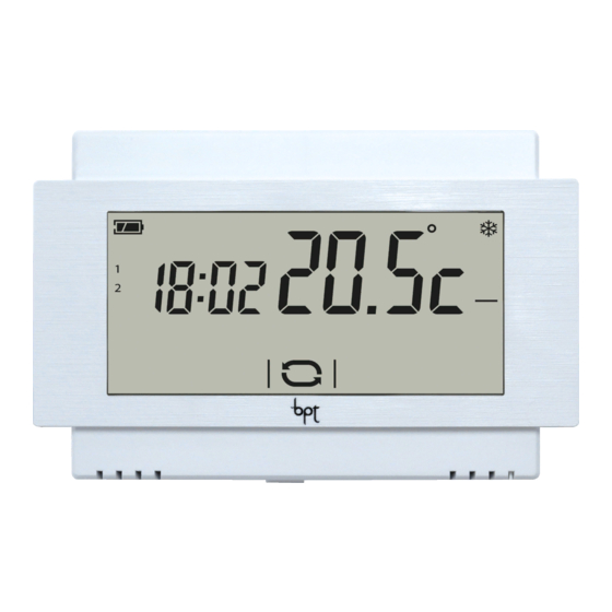
Funzionamento del dispositivo Alla prima accensione A il cronotermostato si trova in modalità riscaldamento automatico; sul display viene visualizzata la temperatura rilevata. Sul diagramma lampeggia la colonnina corrispondente all'ora corrente e la freccia indica il giorno della settimana. NOTA. Quando il dispositivo si trova in stand-by, il primo tocco sullo schermo accende la retro-illumi- nazione e non esegue alcun comando. - Page 8 Cambiare la modalità di funzionamento dell'impianto Toccare l'area evidenziata nella figura A e mantenere il tocco fino a quando un segnale acustico indica la variazione di modalità tra: Impianto in modalità Riscaldamento Impianto in modalità Raffrescamento Impianto Spento Impianto in modalità Antigelo Quando l'impianto viene spento ( ), per alcuni secondi sullo schermo viene visualiz- zata l'immagine della figura B ad indicare...
- Page 9 Personalizzare la programmazione ③ settimanale della temperatura ② Utilizzare le frecce per visualizzare sul display la temperatura programmata per ① l'ora selezionata A. ① Giorno visualizzato ② Ora selezionata ③ Temperatura programmata Utilizzare le frecce per modificare la programmazione della temperatura per l'ora selezionata B.
- Page 10 Copiare l'andamento termico di una giornata su altri giorni Brevi tocchi sulla parte dello schermo eviden- ziata, permettono di visualizzare l'andamen- to termico giornaliero che si desidera copiare. Mantenere il tocco nell'area evidenziata in figura A fino a quando appare la schermata di figura B.
- Page 11 di modifica del livello di temperatura T2 F. Procedere come precedentemente illustrato per impostare livello di temperatura T3. Uso del programma Jolly Il programma Jolly può essere utilizzato, durante feste infrasettimanali, ferie, ecc.. Può essere avviato in qualsiasi momento del giorno in corso e rimanere attivo fino al termine del giorno stesso, oppure prenotato per uno qualsiasi dei giorni della settimana.
- Page 12 Modalità manuale Per attivare questa modalità premere il A fino alla comparsa pulsante dell'icona Usare le frecce per impostare la temperatura di zona desiderata B; il valore inserito rimarrà valido fino a quando non verrà cambiata la modalità di funziona- mento o il valore impostato.
- Page 13 Esclusione dal controllo termico Per attivare questa modalità premere il A fino alla comparsa pulsante dell'icona Se l'impianto è in modalità "Riscaldamento", la funzione antigelo rimane attiva. Per qualche secondo viene mostrata la temperatura impostata per l'antigelo poi viene visualizzata l'ora corrente e la tempe- ratura rilevata.
-
Page 14: Sblocco Dello Schermo
Sblocco dello schermo Se il blocco dello schermo è abilitato A, premendo in una qualunque area sensibile dello schermo si accede alla schermata di figura B. Il primo numero lampeggia; usare le frecce per scegliere la prima cifra del codice, la freccia per passare alla cifra successiva;... - Page 15 Configurazione dei parametri generali del dispositivo A è possibile Quando il dispositivo si trova in modalità Manuale , mantenendo premuto il pulsante accedere alle schermate di configurazione del dispositivo. Nota. Dopo l'accesso alle schermate di configurazione, la pressione del pulsante permette di visualizzare in sequenza i parametri da configurare, il pulsante permette di uscire dalla finestra di configurazione...
- Page 16 Modificare la calibrazione della sonda di rilevamento della temperatura Se la collocazione del dispositivo non consente una corretta rilevazione della temperatura è possibile modificare la temperatura rilevata di ±3 °C con incrementi di un decimo di grado. Usare le frecce per modificare il dato rilevato del valore desiderato e premere il pulsante...
- Page 17 Impostare il tipo di algoritmo di gestione termica Il dispositivo permette di scegliere il tipo di algoritmo da applicare per la gestione dell'impianto tra: • Differenziale • Proporzionale Integrale Algoritmo Differenziale A Se alla schermata A, mediante le frecce si è scelto il tipo di algoritmo differenziale, premere il pulsante per personalizzare, B, il valore del...
- Page 18 Il programma P4 può essere compilato secondo necessità. figura E per poter Premere il pulsante F, la inserire, mediante le frecce durata di un ciclo. figura F per poter Premere il pulsante G, il inserire, mediante le frecce tempo minimo di accensione. figura G per poter Premere il pulsante H, il valore...
- Page 19 Impostare l'unità di misura della temperatura Scegliere l'unità di misura della temperatura usando le frecce Premere il pulsante per passare al para- metro successivo da configurare. Utilizzo dei morsetti (solo su modello a pile) Scegliere la funzione associata ai morsetti B tra: usando le frecce = sonda remota compatibile...
- Page 20 Attivazione da remoto mediante contatto telefonico (solo su modello a pile) Collegando ai morsetti un’apposita interfaccia telefonica è possibile eseguire, mediante il proprio telefono, due tipi di attivazione: 1. Attivazione da remoto del programma Manuale a tempo: per l’attivazione di questo programma è...
- Page 21 Contatto finestra (solo su modello a pile) Collegando ai morsetti un contatto finestra D ( ), è possibile fare in modo che la zona termica venga spenta dopo trenta secondi dall'apertura della finestra nella quale è montato il contatto. Nota. Richiudendo la finestra la zona termica torna nella modalità...
- Page 22 Conteggio ore di attività La schermata di figura A riporta le ore di attività del dispositivo. Per azzerare il contatore, premere in maniera prolungata nell'area evidenziata in figura. Premere il pulsante per passare al para- metro successivo da configurare. Versione firmware La schermata di figura B riporta il nu- mero della versione firmware installata nel dispositivo.
-
Page 23: Caratteristiche Tecniche
Caratteristiche tecniche TH500 alimentato da batteria TH500 alimentato da rete • Alimentazione: 2 pile stilo alcaline LR6 tipo AA da • Alimentazione: 230 Vac 50/60Hz. 1,5V (non fornite in dotazione). • Assorbimento: 16mA. • Autonomia batteria: Maggiore di 1 anno. •... - Page 25 TH/500 24810740 Installer and user manual www.bpt.it English...
-
Page 26: General Notes
The components that should be recycled are marked with the material’s ID marker. EC Declaration - BPT S.p.A. a Socio Unico declares that this device complies with directives 2004/108/EC and 2006/95/EC. Originals upon request. -
Page 27: Description Of Device
Description of device ⑰ ③ ④ ⑤ ⑨ ⑩ ① ⑪ ⑬ ② ⑮ ⑯ ⑫ ⑱ ⑭ ⑲ ⑦ ⑥ ⑧ Battery charge status Remote activation in progress ① ⑩ (only on battery-powered version) (only on battery-powered version) Window contact active ②... -
Page 28: Wall-Mounted Installation
Installation Install the unit in a position which is suitable for cor- rect room temperature measurement, for example on an internal wall. Avoid installation in alcoves, behind doors or curtains, or near heat sources. Wall-mounted installation • Open the device by pressing the button on the bot- tom B, with your finger ①... -
Page 29: Electrical Connections
Electrical connections. The connections are made according to the type of equipment controlled by the programmable thermostat. VALVE Figures D and E refer to the OPEN mains-powered programmable thermo- stat but are also valid for the battery-pow- CLOSED ered version, only for the part relating to the relay contacts. - Page 30 NOTE. In the mains-powered device, in the event of there being no power supplied, the relay remains in the state prior to the power outage. Inserting/replacing batteries (only on battery-powered model) Insert 2 AA 1.5V LR6 penlight alkaline batteries (not supplied with purchase) into the relative slot, respecting the polarities shown on the bottom of the housing G.
-
Page 31: Operation Of Device
Operation of device When first turned on, A the programmable thermostat is in automatic heating mode; the temperature detected is shown on the display. On the diagram the column corresponding to the current time is flashing and the arrow indicates the day of the week. NOTE. - Page 32 Changing the system's operating mode Touch the area shown in figure A and continue touching until a beep indicates the mode is changed between: System in Heating mode System in Cooling mode System off System in Frost-protection mode When the system is off ( ), the image in figure B is displayed on the screen for a few seconds, to indicate that the programmable thermostat is off;...
- Page 33 Customising weekly temperature programming ③ ② Use the arrows to view the temperature set for the time selected on the display A. ① ① Day displayed ② Time selected ③ Programmed temperature Use the arrows to change the temperature set for the time selected B. Once the temperature trend for the day has been set, move on to programming the next day by briefly touching the temperature/...
- Page 34 Copying the temperature trend from one day to other days Brief touches on the part of the screen highlighted allow the daily temperature trend that you want to copy to be displayed. Keep touching the area highlighted in figure A until the screen in figure B appears. Brief touches on the highlighted area of the screen allow the arrow that indicates the days of the work to be moved to the day you want...
- Page 35 Proceed as described above to set temper- ature level T3. Use of the all-purpose program The all-purpose program can be used during midweek holidays, public holidays, etc. It can be started up at any time of the day in course and stay on until the end of that day, or be set up in advance for any day of the week.
-
Page 36: Manual Mode
Manual mode To activate this mode press button icon appears B. until the Use the arrows to set the desired zone temperature B; the value entered will remain valid until the operating mode or value set is changed. Note. If no button is pressed for 5 seconds the device goes back to showing the tem- perature detected. - Page 37 Exclusion from thermal control To activate this mode press button icon appears B. until the If the system is in "Heating" mode, the frost-protection function remains on. The frost-protection temperature set is shown for a few seconds, then the current time and temperature detected are displayed.
-
Page 38: Unlocking The Screen
Unlocking the screen If screen lock is enabled A, pressing on any sensitive area of the screen gives access to the window shown in figure B. The first number flashes; use the arrows to choose the first digit of the code, and the arrow to move on to the next digit;... - Page 39 Configuration of general parameters of the device button A gives access to the device's config- When the device is in Manual mode , holding down the uration screens. Note. After accessing the configuration screens, pressing the button lets you display the parameters to be configured in sequence, the button lets you exit the configuration window and go back to the screen in figure A.
- Page 40 Changing the calibration of the temperature detection probe If the location of the device does not permit suitable detection of the temperature, it is possible to change the temperature detected by ±3 °C with increases of a tenth of a degree. Use the arrows to change the data detected by the desired value and press the...
- Page 41 Setting the type of heat management algorithm The device lets you choose the type of algorithm to apply for the management of the system between: • Differential • Proportional Integral Differential Algorithm A If, on screen A, using the arrows, the differential algorithm type has been chosen, press the button to customise the value of...
- Page 42 Program P4 can be made up as required. button in figure E to be able Press the to enter the duration of a cycle, using the arrows F. button in figure F to be able Press the to enter the minimum on time, using the arrows G.
- Page 43 Setting the unit of measurement for the temperature Choose the unit of measurement for the arrows A. temperature using the Press the button to move on to the next parameter to be configured. Use of terminals (only on battery-powered model) Choose the function associated with the termi- arrows B from: nals...
- Page 44 Remote activation via phone (only on battery-powered model) By connecting a suitable telephone interface to the terminals you can carry out two types of activation from your phone: 1. Remote activation of the timed Manual program: to activate this program the input (terminals must be closed for at least 2 secs and not more than 5 secs.
-
Page 45: Adjusting Display Brightness
Window contact (only on battery-powered model) If you have chosen to connect to the terminals a window contact D ( ), you can set it so that the thermal zone is turned off thirty seconds after the window in which the contact is fitted is opened. -
Page 46: Firmware Version
Hours of activity counter The screen in figure A shows the device's hours of activity. To reset the counter to zero, press it for a long time in the area highlighted in the figure. Press the button to move on to the next parameter to be configured. -
Page 47: Technical Features
Technical features Battery-powered TH500 Mains-powered TH500 • Power supply: 2 alkaline LR6 penlight AA 1.5V • Power supply: 230 Vac 50/60Hz batteries (not supplied). • Consumption: 16mA. • Battery life: More than 1 year. • Autonomous life without power supply: • Time available for replacement of batteries: about 10 hrs.
Need help?
Do you have a question about the TH/500 and is the answer not in the manual?
Questions and answers
Come faccio a sbloccare il termostato, bloccato per sbaglio, non so il codice. Grazie
To unlock the Bpt TH/500 thermostat if it is accidentally locked and the code is unknown, follow these steps:
1. Tap any sensitive area on the screen to access the unlock screen.
2. The first digit of the code will start blinking.
3. Use the arrow buttons to select the first digit.
4. Press the arrow button to move to the next digit and repeat the process.
5. Once all digits are entered, press the confirmation button to unlock the screen.
If the code is unknown, a hard reset to factory default settings may be necessary to regain access. This will erase all settings and require reconfiguration.
This answer is automatically generated
@Mr. Anderson, salve,ma un codice di fabbrica non ne ha questo termostato?grazie