
Related Manuals for Bpt TA/500


Summary of Contents for Bpt TA/500
- Page 1 TA/500 24811370 Manuale d’installazione e d’uso Installer and user manual www.bpt.it Italiano English...
-
Page 2: Avvertenze Generali
Sui componenti, per cui è previsto lo smaltimento con riciclaggio, sono riportati il simbolo e la sigla del materiale. Dichiarazione CE - BPT S.p.A. a Socio Unico, dichiara che questo dispositivo è conforme alle direttive 2004/108/EC e 2006/95/EC. Originali su richiesta. - Page 3 Descrizione dispositivo ④ ⑨ ⑤ ⑥ ⑦ ⑧ ① ⑬ ⑮ ② ⑰ ③ ⑱ ⑭ ⑯ ⑪ ⑩ ⑫ Stato di carica della batteria Pulsante per cambiare la modalità ① ⑩ (solo su versione a pile) della zona termica Contatto finestra attivo Pulsante per accedere al setup del ②...
-
Page 4: Installazione A Parete
Installazione Installare il dispositivo in posizione idonea a rile- vare correttamente la temperatura dell’ambiente, possibilmente in una parete interna, evitando l’installazione in nicchie, dietro a porte, a tende o vicino a sorgenti di calore. Installazione a parete • Aprire il dispositivo premendo il pulsante posto sul fondo del dispositivo B, con il dito ①... -
Page 5: Collegamenti Elettrici
Collegamenti elettrici I collegamenti vanno effettuati in funzio- ne del tipo di apparecchiatura comanda- ta dal cronotermostato. VALVOLA Le figure D e E sono riferite al APERTA cronotermostato alimentato da rete ma sono valide anche per la versione CHIUSA alimentata da pile, limitatamente alla parte dei contatti relè. - Page 6 NOTA. Nel dispositivo alimentato da rete, in caso di mancanza di alimentazione, il relè rimane nello stato precedente la caduta di tensione. Inserimento/sostituzione delle pile (solo su modello a pile) Inserire n. 2 pile alcaline LR6 tipo stilo AA da 1,5V (non fornite in dotazio- ne) nell’apposita sede rispettando le polarità...
-
Page 7: Funzionamento Del Dispositivo
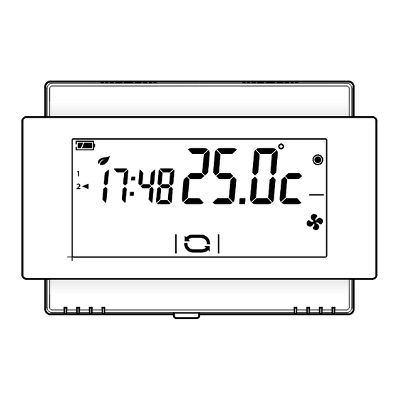
Funzionamento del dispositivo Alla prima accensione A il cronotermostato si trova in modalità riscaldamento ed è attivo il programma Comfort; sulla parte destra del display viene visualizzata la temperatura rilevata. NOTA. Quando il dispositivo si trova in stand-by, il primo tocco sullo schermo accende la retro- illuminazione e non esegue alcun comando. - Page 8 Cambiare la modalità di funzionamento dell'impianto Toccare l'area evidenziata nella figura A e mantenere il tocco fino a quando un segnale acustico indica la variazione di modalità tra: Impianto in modalità Riscaldamento Impianto in modalità Raffrescamento Impianto Spento Impianto in modalità Antigelo Quando l'impianto viene spento ( ), per alcuni secondi sullo schermo viene visualiz- zata l'immagine della figura B ad indicare...
- Page 9 Ad ogni pressione viene mostrato, per qualche secondo, il programma attivato e la temperatura desiderata preprogrammata EF; successivamente riappare l'ora corrente e la temperatura rilevata. Esclusione dal controllo termico Per attivare questa modalità premere D fino alla comparsa il pulsante dell'icona Se l'impianto è...
- Page 10 Altri dati visualizzabili sulla pagina principale Premendo brevemente sull'area dove viene visualizzata la temperatura rilevata A, in luogo dell'ora viene visualizzata la temperatura obbiettivo (set point) B. Premere nuovamente sull'area evidenziata A per tornare alla modalità di visualizza- zione precedente. Visualizzare la temperatura rilevata da una sonda esterna Se al dispositivo è...
- Page 11 Procedere come precedentemente spiega- to per apportare modifiche alla program- mazione e procedere allo stesso modo per tutti i programmi preimpostati Nota. Le modifiche hanno effetto per la programmazione relativa all'Utente attivo. Sblocco dello schermo Se il blocco dello schermo è abilitato G, premendo in una qualunque area sensibile dello schermo si accede alla schermata di figura H.
- Page 12 Configurazione dei parametri generali del dispositivo Quando il dispositivo si trova in modalità "Esclusione dal controllo termico" (vedi pagina 9), mante- A è possibile accedere alle schermate di configurazione del dispositivo B. nendo premuto il pulsante Nota. Dopo l'accesso alle schermate di configurazione, la pressione del pulsante permette di visualizzare in sequenza i parametri da configurare, il pulsante permette di uscire dalla finestra di configurazione...
- Page 13 (password) che dovrà essere digitato per sbloccare il dispositivo. Il primo numero lampeggia E; usare le frecce per inserire la prima cifra del codice, la freccia per passare alla cifra successiva; in qualunque momento pre- mendo il pulsante il codice digitato viene considerato valido e si passa al parametro successivo da configurare.
- Page 14 Questa funzione risulta utile per ambienti particolarmente difficili da climatizzare, con Set-point + differenziale variazioni estreme della temperatura ester- Set-point na e comanda l'accensione dell'impianto come illustrato in figura I. Set-point – differenziale Tempo Algoritmo Proporzionale Integrale Se alla schermata G, mediante le frecce si è...
- Page 15 figura M per poter Premere il pulsante N, il inserire, mediante le frecce valore della banda proporzionale. Premere il pulsante per passare al para- metro successivo da configurare. Set-point Tempo Durata ciclo Tempo minimo di Banda Prog. Tipo di impianto (minuti) ON (minuti) Proporzionale...
- Page 16 Utilizzo dei morsetti (solo su modello a pile) Scegliere la funzione associata ai morsetti A tra: usando le frecce = sonda remota compatibile = contatto telefonico = contatto finestra Scelta della sonda principale (solo su modello a pile) Se si è scelto di collegare ai morsetti una sonda esterna ( ), premendo il pulsante...
- Page 17 Usando le frecce è possibile impo- stare la modalità di funzionamento che il dispositivo deve assumere alla ricezione del comando telefonico remoto. = Riscaldamento = Raffrescamento Premere il pulsante per passare al para- metro successivo da configurare. Contatto finestra (solo su modello a pile) Se si è...
- Page 18 "Bip" pulsanti Scegliere se attivare/disattivare il "bip" pulsanti usando le frecce Premere il pulsante per passare al para- metro successivo da configurare. Conteggio ore di attività La schermata di figura B riporta le ore di attività del dispositivo. Per azzerare il contatore, premere in maniera prolungata nell'area evidenziata in figura.
-
Page 19: Caratteristiche Tecniche
Nota. In tutti i modelli del dispositivo, la momentanea mancanza di energia causata da assenza di ten- sione sulla rete o sostituzione della batteria, NON comporta la cancellazione di alcuna programmazione. Caratteristiche tecniche TA500 alimentato da batteria TA500 alimentato da rete •... - Page 21 TA/500 24811390 Installer and user manual www.bpt.it English...
-
Page 22: General Notes
The components that should be recycled are marked with the material’s ID marker. EC Declaration - BPT S.p.A. a Socio Unico declares that this device complies with directives 2004/108/EC and 2006/95/EC. Originals upon request. -
Page 23: Description Of Device
Description of device ④ ⑨ ⑤ ⑥ ⑦ ⑧ ① ⑬ ⑮ ② ⑰ ③ ⑱ ⑭ ⑯ ⑪ ⑩ ⑫ Battery charge status ① ⑩ Button to change thermal zone mode (only on battery-powered version) Window contact active ② ⑪... -
Page 24: Wall-Mounted Installation
Installation Install the unit in a position which is suitable for cor- rect room temperature measurement, for example on an internal wall. Avoid installation in alcoves, behind doors or curtains, or near heat sources. Wall-mounted installation • Open the device by pressing the button on the bottom B, with your finger ①... -
Page 25: Electrical Connections
Electrical connections The connections are made according to the type of equipment controlled by the programmable thermostat. VALVE Figures D and E refer to the OPEN mains-powered programmable ther- mostat but are also valid for the bat- CLOSED tery-powered version, only for the part relating to the relay contacts. - Page 26 NOTE. In the mains-powered device, in the event of there being no power supplied, the relay remains in the state prior to the power outage. Inserting/replacing batteries (only on battery-powered model) Insert 2 AA 1.5V LR6 penlight alkaline batteries (not supplied with purchase) into the relative slot, respecting the polarities shown on the bottom of the housing G.
-
Page 27: Operation Of Device
Operation of device When first turned on, A the programmable thermostat is in heating mode and the Comfort program is on; the right-hand side of the display shows the temperature measured. NOTE. When the device is in stand-by, the first touch on the screen switches on the back-lighting and does not carry out any command. - Page 28 Changing the system's operating mode Touch the area shown in figure A and continue touching until a beep indicates the mode is changed between: System in Heating mode System in Cooling mode System off System in Frost-protection mode When the system is off ( ), the image in figure B is displayed on the screen for a few seconds, to indicate that the system is off;...
- Page 29 Each time it is pressed, it shows the program in activation and the pre-set desired tempera- ture for a few seconds EF; then the current time and temperature detected reappear. Exclusion from thermal control To activate this mode press button icon appears D.
- Page 30 Other information that can be displayed on the main page By briefly pressing on the area where the temperature detected is displayed A, the objective temperature (set point) is displayed in place of the time B. Press the highlighted area again A to go back to the previous display mode.
-
Page 31: Unlocking The Screen
Proceed as explained before to make chang- es to the programming and do the same for all the pre-set programs Note. The changes are effective for pro- gramming relating to the active User. Unlocking the screen If screen lock is enabled G, pressing on any sensitive area of the screen gives access to the window shown in figure H. - Page 32 Configuration of general parameters of the device When the device is in "Exclusion from thermal control" mode (see page 9), holding down the button A gives access to the device's configuration screens B. Note. After accessing the configuration screens, pressing the button lets you display the parameters to be configured in sequence, the button lets you exit the configuration window and go back to the...
- Page 33 The first number flashes E; use the arrows to enter the first digit of the code, and the arrow to move on to the next digit; pressing button at any time means the code entered is considered valid and you move on to the next parameter to be configured.
- Page 34 This function is useful for environments that are particularly hard to air condition, with Set-point + differential extreme variations in external temperature Set-point and commands the switching on of the system as shown in figure I. Set-point – differential Time Proportional Integral Algorithm If, on screen G, using the arrows,...
- Page 35 button in figure M to be able Press the to enter the value of the proportional band, arrows N. using the Press the button to move on to the next parameter to be configured. Set-point Time Cycle duration Minimum ON time Proportional Prog.
- Page 36 Use of terminals (only on battery-powered model) Choose the function associated with the termi- arrows A from: nals using the = compatible remote probe = telephone contact = window contact Choice of main probe (only on battery-powered model) If you have chosen to connect to the termi- nals an external probe ( pressing the...
-
Page 37: Adjusting Display Brightness
Using the arrows you can set the op- erating mode that the device must take up on receipt of the remove phone command. = Heating = Cooling Press the button to move on to the next parameter to be configured. Window contact (only on battery-powered model) If you have chosen to connect to the termi-... -
Page 38: Firmware Version
Buttons beep Choose whether to activate/deactivate the arrows A. buttons beep using the Press the button to move on to the next parameter to be configured. Hours of activity counter The screen in figure B shows the device's hours of activity. To reset the counter to zero, press it for a long time in the area highlighted in the figure. -
Page 39: Technical Features
Note. In all models of the device, the temporary lack of power caused by a mains power outage or replacing the battery, does NOT lead to any programming being deleted. Technical features Battery-powered TA500 Mains-powered TA500 • Power supply: 2 alkaline LR6 penlight AA 1.5V •...
Need help?
Do you have a question about the TA/500 and is the answer not in the manual?
Questions and answers