Table of Contents
Advertisement
Available languages
Available languages
Advertisement
Chapters
Table of Contents

Related Manuals for Bpt TH 345


Summary of Contents for Bpt TH 345
- Page 1 TH 345 PROGRAMMABLE THERMOSTAT THERMOPROGRAM PROGRAMMIERBARER RAUMTHERMOSTAT THERMOPROGRAM THERMOSTAT PROGRAMMABLE THERMOPROGRAM INSTRUCTIONS FOR USE GEBRAUCHS- ANWEISUNG MODE D’EMPLOI...
- Page 2 Congratulations on your purchase RECOMMENDATIONS DISPOSAL of the TH345 thermostat. FOR THE INSTALLER To get the best performance and Do not litter the environment with make the best use of the features • Read the contents of the follo- packing material: make sure it is and functions of your thermostat, wing pages with care because they disposed of according to the regu-...
- Page 3 No. 1 adapter for the VIMAR idea No. 1 hole plug ses: range of front plate No. 1 BPT front plate No. 1 chassis with 2 screws for No. 1 thermostat body No. 1 adapter for front plate fixing the chassis to the embed-...
- Page 4 1 2 3 4 5 6 7 1 2 3 4 5 6 7 Fig. 1...
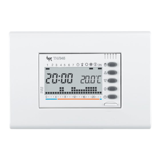
- Page 5 KEY TO SYMBOLS AND HEATING program. Disable thermostat OUTSIDE CONTROLS , figure 1 control of the plant. Antifreeze function. SYMBOLS Thermostat enabled. INSIDE 1 0 ÷ 23 Time scale in the pro- CONTROLS Time bands when the gram graph. heating/cooling plant To access these inside controls, Flashing of the cursor operates.
- Page 6 0÷23 Moves the time in the daily program graph backwards. 24 0÷23 Moves the time in the daily program graph forwards. 25 1÷7 Selection the day of the week. 26 C Copy program. 0 23 19 20 21 22 23 24 25 26 Fig.
- Page 7 THERMOPROGRAM the various times of the day and TH345 week. The THERMOPROGRAM is extre- mely easy to program, even before The THERMOPROGRAM pro- it is installed; a spacious display grammable thermostat is designed facilitates this operation, since you to ensure ideal temperature condi- can “see”...
-
Page 8: Table Of Contents
CONTENTS 10- Antifreeze function 11- Plant running time Chapter Page 12- Viewing the temperature 1 - Installation level values 2 - Electric connections 13- Stand-by mode 14- Reset 3 - Setting the clock 15- Temperature threshold 4 - Standard programs in permanent memory 16- Replacing the batteries 5 - Manual operation... -
Page 9: Installation
1 - INSTALLATION stops, figure 4, then press gently WARNING. Inserting the batteries on the two side flaps coinciding the wrong way round can damage with the symbol, figure 5, the thermostat. Install the thermostat in a position detach it completely from the box. If the messages on the display do where it can detect the average •... - Page 10 the indications illustrated in figure 7. • Make the electric connections to the terminal block of the housing as illustrated in the diagrams in figure 12A or 12B. BODY • Fix the housing to the flush-moun- FRONT PLATE BTICINO ted junction box by means of the two (Art.
-
Page 11: Electric Connections
the use of different types of front panel available on the market, figure 9-10 and 11. VIMAR ADAPTER 2 - ELECTRIC CONNECTIONS The connections must be made according to the type of equipment being controlled by the thermostat; FRONT ADAPTER refer, therefore, to the diagram in PLATE: figures 12A or 12B. - Page 12 CHASSIS GEWISS BODY FRONT LOAD PLATE (Playbus) TH / 345 Fig. 12A LOAD OPEN HOLE PLUG ADAPTER CLOSED 3-MODULES (without EMBEDDING connecting rods) TH / 345 Fig. 11 Fig. 12B...
-
Page 13: Setting The Clock
3 - SETTING The indicator for the days of the 1 2 3 4 5 6 7 THE CLOCK week flashes. 3.7 - Press button until 3.1 - Remove the body from the the right day is displayed, figure 18. housing. -
Page 14: Standard Programs In Permanent Memory
from the minutes flash to confirm 4 - STANDARD T1 16 °C the end of the procedure. PROGRAMS T2 18 °C In any case, the thermostat auto- IN PERMANENT T3 20 °C matically abandons this procedure, MEMORY memorizing the latest settings, 10 4.2 - COOLING PROGRAM s after the last operation. -
Page 15: Manual Operation
the THERMOPROGRAM needs no reading refers to the previously-set change to another operating mode. further explanation and is ready to temperature, which can be varied TIMER-CONTROLLED operate immediately. at will by means of the MANUAL OPERATION To create personalized programs, button (the thermostat is despat- on the other hand, proceed as ched with a default temperature... - Page 16 AUTOMATIC mode, running the grammed interval, press the temperature by pressing system according to the preset button, figure 27. 5.3 - Press the button once, program. figure 25. The display shows the wording Programming in days Programming in hours h01 instead of the actual time. 5.5 - Make sure that you are 5.1 - Make sure that you are in 5.4 - Press the button...
-
Page 17: Personalizing Temperature Level Values For The Heating Program
The days are counted including the appears on the display and the grammed interval, press the day during which the program- value of the temperature assigned button, figure 30. ming option is used (so the to T1 (16 °C in the permanent 6 - PERSONALIZING remainder of the day when the set- memory) is indicated instead of... -
Page 18: Personalizing Temperature Level Values For The Cooling Program
6.5 - Press button T to confirm T3 is set at 20 °C and level T1 is set rations being performed, the ther- the temperature value indicated on at 16 °C, the value of T2 can only mostat abandons the procedure, the display and move on to the be set between 16.1 °C and 19.9 retaining the most recent settings. - Page 19 8.2 - Using the 1÷7 button, bring selected for the time indicated by days progressively indicated by the the indicator round to the 1 posi- the flashing bar. corresponding bar. tion (Monday), figure 35. 8.4 - Using the button, 8.6 - To program the subsequent 8.3 - Using the 0÷23 but-...
-
Page 20: Wild Card Program
gramming sequence, you can be performed at any time, at will. mostat’s permanent memory is return immediately to the current 8.8 - Replace the thermostat in the same as the Sunday (7) pro- day and time by pressing the its housing. gram, but it can be personalized. - Page 21 apply in this case). you need, figure 44. button and then pressing the At midnight, THERMOPROGRAM 9.8 - Press the button, figure 45. button. returns to automatic mode. The bar under the symbol is Alternatively, you can cancelled the 9.4 - To abandon the WILD CARD enabled to confirm that the pro- setting by pressing the button...
-
Page 22: 10- Antifreeze Function
10 - ANTIFREEZE figure 49. THE TIMER-CONTROLLED FUNCTION The bar under the symbol ANTIFREEZE FUNCTION comes on to confirm the choice. If it proves necessary in winter to In the event of your needing to The program graph disappears maintain a safe minimum tempera- keep a safe minimum temperature from the screen and the pre- ture while away, use the ANTI-... - Page 23 setting is made counts as a whole by means of the button, 1 2 3 4 5 6 7 hour). figure 50. Note. To return to AUTOMATIC Programming in hours mode before the expiry of the the 10.3 - Press the button once, programmed interval, press the figure 52.
-
Page 24: 11- Plant Running Time
The days are counted including the 9,999) which enables you to keep a 12 - VIEWING THE day during which the program- count of the plant running times. TEMPERATURE ming option is used (so the 11.1 - To check this value, bring LEVEL VALUES remainder of the day when the set- the thermostat into MANUAL... -
Page 25: 13- Stand-By Mode
button T to end the procedure. the display shows the temperature The bar under the symbol is 12.5 - Replace the thermostat in values assigned to the various enabled to confirm the fact that the its housing. levels, figure 62. THERMOPROGRAM is not control- Note. - Page 26 For 5 s the room temperature rea- from 1 to 99, figure 67. The hours The bar under the , symbol is ding disappears and the display are counted including the hour enabed to confirm the fact that the reads: during which the programming THERMOPROGRAM is not control- option is used (so the remainder of...
-
Page 27: 14- Reset
enabled to confirm the fact that the grammed interval, press the 13.8 - Press the button THERMOPROGRAM is not control- until you reach the number of days button or the button. ling the plant and the program required, which can range from 1 graph disappears, figure 70. -
Page 28: 15- Temperature Threshold
red, together with the other set- for systems with a high thermal the required value is displayed, ting, by taking the steps explained inertia, such as systems with cast- figure 74. from chapter 3 onwards. iron radiators. If the features of the 15.5 - Press button T again, or plant make necessary to change wait 10 s, to end the programming... - Page 29 month to replace the batteries remove the body of the thermostat before the unit stops working. from the housing, sliding it out When the message stays on until it stops, figure 76, and then permanently on the display, the unit pressing the two side wings to is no longer working and has turned detach it completely, figure 77.
-
Page 30: 17- Technical Features
press the reset button R (fig. 71). • Power supply: three LR03, type grammable between +2 °C and Replace the thermostat body right AAA, 1.5V alkaline batteries. +35 °C. down in its housing and insert the • Battery life: over one year. •... - Page 31 GENERAL GUARANTEE TERMS The guarantee on the product will be provided by national BPT distri- butor or by local dealer, according to the laws in force in the Country. LU MA ME GI VE SA DO 83,5 Fig. 79...
- Page 32 Wir beglückwünschen Sie zur Wahl HINWEISE FÜR DEN ENTSORGUNG des Raumthermostaten TH345. INSTALLATEUR Für beste Leistungen und die kor- Vergewissern Sie sich, dass das • Lesen Sie die in diesem Heft gege- rekte Kenntnis der Merkmale und Verpackungsmaterial gemäß den benen Anweisungen sorgfältig Funktionen Ihres Thermostaten Vorschriften des Bestimmungs-...
- Page 33 Der Thermostat TH345 besteht 1 Adapter für VIMAR-Platte, Serie 1 Adapter Abdeckklappe aus den folgenden Komponenten: idea 1 BPT-Platte 1 Gehäuse und 2 Schrauben für 1 Körper 1 Adapter für AVE-Platte, System dessen Befestigung Unterputzdose.
- Page 34 1 2 3 4 5 6 7 1 2 3 4 5 6 7 Abb. 1...
- Page 35 ANZEIGEN UND ÄUSSERE K L I M AT I S I E R U N G - Mehrfachfunktion. TASTEN (siehe Abb. 1) Programm. Ausschluß der Anlage. HEIZUNGS-Programm. ANZEIGEN Frostschutzfunktion. 1 0 ÷ 23 Stunden-Skala INNERE TASTEN Programmgraphik. Anlage in Betrieb. Für den Zugriff auf die inneren Der blinkende Cursor Einschaltzeiten der An-...
- Page 36 Programmwahl KLI- MATISIERUNG oder HEIZUNG ( 0÷23 Verminderung der Uhr- zeit in der Graphik des Tagesprogrammes. 24 0÷23 Steigerung der Uhrzeit in der Graphik des Tagesprogrammes. 25 1÷7 Wahl des Wochenta- ges. 26 C Kopieren des Program- mes. 0 23 LU DO 19 20 21 22 23 24 25 26 Abb.
- Page 37 THERMOPROGRAM für die verschiedenen Tageszeiten TH345 und Wochentage gewünschte Temperatur eingestellt wird. Die Programmierung von THER- Der programmierbare Raumther- MOPROGRAM ist extrem einfach mostat THERMOPROGRAM und kann auch vor der Installation TH345 wurde so konzipiert, daß zu erfolgen; das großflächige Display jeder Tageszeit und an jedem Tag erleichtert diesen Vorgang, denn der Woche ideale Temperatur-...
- Page 38 INHALTSVERZEICHNIS 11- Betriebszeit der Anlage 12- Anzeige des Wertes der Temperaturbereiche Kapitel Seite 13- Ausschluß der Anlage 1 - Installation 14- Reset 2 - Elektroanschlüsse 15- Wärmedifferential 3 - Einstellen der Uhr 16- Wechseln der Batterien 4 - Gespeicherte Programme 44 17- Technische Daten 5 - Manueller Betrieb - Allgemeine...
-
Page 39: Installation
1 - INSTALLATION Anschlag aus dem Gehäuse ziehen ungen am Boden des Batterie- (Abb. 4); anschließend an den raums in den speziellen Raum ein- Installieren Sie das Gerät an einem Symbolen (Abb. 5) auf die setzen (Abb. 6). Ort, an dem die Raumtemperatur Seiten drücken und das Gerät ganz ACHTUNG. - Page 40 Resettaste R drücken (Abb. 71). Sofern die beschriebenen Vorgän- ge korrekt ausgeführt wurden, erscheinen Display BPT- KÖRPEN Angaben der Abb. 7. PLATTE BTICINO- • Die Elektroanschlüsse an der PLATTE Klemmleiste des Gehäuses herstel- (Art. L4803) len, wie in den Schaltplänen Abb.
-
Page 41: Elektroanschlüsse
Gehäuse einsetzen und die Platte aufsetzen. Die Lasche L einschieben. ANMERKUNG. Das Gerät wird mit ADAPTER FÜR drei Adaptern für die Verwendung VIMAR-PLATTE eventueller handelsüblicher Plat- ten geliefert (Abb. 9, 10 und 11). 2 - ELEKTROANSCHLUSSE ADAPTER FÜR Die Anschlüsse richten sich nach VIMAR- AVE-PLATTE PLATTE... - Page 42 GEWISS- CHASSIS KÖRPEN PLATTE BELASTUNG (Playbus) TH / 345 Abb. 12A BELASTUNG ADAPTER OFFEN ABDECK- KLAPPE GESCHLOSSEN (ohne UNTERPUTZ- Verbindung- DOSE MIT 3 stangen) MODULEN TH / 345 Abb. 11 Abb. 12B...
-
Page 43: Einstellen Der Uhr
Belastungen Die Stundenziffern blinken. U1 = Brenner, Umwälzpumpe, 1 2 3 4 5 6 7 3.5 - Die Taste oder drüc- Elektroventil, usw. ken, bis der gewünschte Wert für U2 = motorisiertes Ventil die exakte Stunde erhalten ist (Abb. 16). 3 - EINSTELLEN DER UHR 3.6 - Die Taste (Abb. -
Page 44: Gespeicherte Programme
den Abschluß des Vorgangs an. 4 - GESPEICHERTE 3.7 - Die Taste oder drüc- Das Gerät springt in jedem Fall 10 PROGRAMME ken, bis der laufende Tag erhalten s nach der letzten Operation auto- ist (Abb. 18). 4.1 - HEIZPROGRAMM matisch von dieser Funktion ab 3.8 - Die Taste drücken, um... -
Page 45: Manueller Betrieb
4.2 - KLIMATISIERUNGSPRO- duellen Programmen siehe Absät- verändert werden kann (das Gerät GRAMM ze 6, 7 und 8 . wird mit einem voreingestellten Das gespeicherte Klimatisierungs- Temperaturwert von 20 °C gelie- programm sieht den Temperaturver- fert) (Abb. 24). Zirka 5 s nach der 5 - MANUELLER BETRIEB lauf der Abb. - Page 46 ZEITGEREGELTER nach dessen Ablauf das Gerät vom 5.4 - Die Taste oder drüc- MANUELLER BETRIEB MANUELLEN zum AUTOMATI- ken, bis die gewünschte Stunden- SCHEN Betrieb übergeht und dem zahl von 1 bis 99 erreicht ist (Abb. eingestellten Programm folgt. Falls eine bestimmte Temperatur 26).
-
Page 47: Individuelle Einstellung Der Temperaturbereiche Für Das Heizprogramm
Sie sich in MANUELLEM Betrieb Programmierung wird als 1 Tag aktiviert ist, indem eventuell die befinden. gezählt) (Abb. 29). Taste gedrückt wird (Abb. 5.6 - Mit der Taste oder Anmerkung. Um vor Ablauf der 31). den gewünschten Temperaturwert programmierten Zeit zum AUTO- 6.3 - Die Taste T drücken (Abb. -
Page 48: Individuelle Einstellung Der Temperaturbereiche Für Das Klimaprogramm
te Temperaturwert angezeigt (ein- T1 gleich 16 °C ist, kann T2 nur Fall 10 s nach der letzten Operation gespeicherter Wert 16 °C). einen Wert zwischen 16,1°C und von dieser Funktion ab und spei- 6.4 - Den für T1 gewünschten 19,9 °C haben. -
Page 49: Täglichen
Punkt 6.3 u.f. beschrieben einstel- Stunde 0 an der Graphik des Tages- (Abb. 37) den gewünschten programmes bringen (Abb. 36). len. Den Gerätekörper wieder ein- Temperaturbereich anwählen; Anmerkung. Wenn man von der schieben. durch Drücken der Taste 0÷23 laufenden Zeit abweicht, ändern zur folgenden Stunde übergehen 8 - INDIVIDUELLE sich die Informationen am Display... -
Page 50: Jolly-Programm
kopiert werden. 8.8 - Den Gerätekörper wieder Sonntags (7), kann beschrieben 8.6 - Um die folgenden Tage einschieben. den individuellen Anforderungen anders zu programmieren, mit der angepasst werden. Um dieses 9 - JOLLY-PROGRAMM Taste 1÷7 auf den nächsten Tag Programm für den laufenden Tag übergehen und wie unter Punkt 8.4 Das Gerät verfügt über ein aufzurufen, wie folgt vorgehen:... - Page 51 8.5 und 8.6 gelten hier nicht). Betrieb zurückgestellt (Abb. 43). Betrieb befinden. Nach Mitternacht stellt sich THER- Falls das JOLLY-Programm für 9.7 - Den Anzeiger mit der Taste MOPROGRAM erneut auf automa- einen anderen Tag voreingestellt 1÷7 auf den gewünschten Tag stel- tischen Betrieb.
-
Page 52: 10- Frostschutzbetrieb
des gewählten Tages an. 9.11 - Den Gerätekörper wieder Programm-Graphik und die zuvor Eine solche Voreinstellung kann einschieben. eingestellte Temperatur, die mit der gelöscht werden, indem der Taste oder verändert wer- Anzeiger mit der Taste 1÷7 auf den den kann (Abb. 50). 10 - FROSTSCHUTZBETRIEB betreffenden Tag gestellt und die Nach ungefähr 5 s erscheint die... - Page 53 °C bis 35 °C möglich, die bis zu 10.4 - Die Taste oder (Abb. nach dessen Ablauf das Gerät zum einer erneuten Einstellung oder der 53) drücken, bis die gewünschte AUTOMATISCHEN Betrieb zurück- Wahl einer anderen Betriebsart kehrt. Stundenzahl von 1 bis 99 erreicht aufrecht erhalten wird.
-
Page 54: 11- Betriebszeit Der Anlage
Programmierung in Tagen Tageszahl von 1 bis 99 erreicht ist. ausgestattet, mit dem die Betriebs- 10.5 - Die Taste zweimal drüc- In der Tageszahl ist auch jener der stunden der Anlage gezählt werden ken (Abb. 55). Programmierung enthalten (das können. Anstelle der laufenden Uhrzeit ers- heißt der Rest des Tages der 11.1 - Um diesen Wert zu kontrol-... -
Page 55: 12- Anzeige Des Wertes Der Temperaturbereiche
11.2 - Den Gerätekörper wieder 12.2 - Die Taste T betätigen (Abb. kann wie folgt erhalten werden: einschieben. 60). Vergewissern Sie sich, ob Sie sich Am Display erscheint der Tempera- in AUTOMATISCHEM Betrieb befin- turbereich T1 und anstelle der den. 12 - ANZEIGE DES WERTES Raumtemperatur wird der T1 Bei Drücken der Taste... - Page 56 winterlichen Reinigungen, War- (Abb. 64). Die Raumtemperatur Das unterhalb aktive Segment tungsarbeiten, sommerlicher Ab- wird 5 s lang angezeigt und ansch- bestätigt den Ausschluß von wesenheit, usw.; das Gerät funktio- ließend erscheint THERMOPROGRAM von der Anla- niert lediglich als Uhr/Thermometer 13.3 - Mit der Taste oder gensteuerung und die Programm-...
- Page 57 ken, bis die gewünschte Stunden- Anstelle der laufenden Uhrzeit ers- Das unterhalb aktive Segment zahl von 1 bis 99 erreicht ist (Abb. cheint am Display die Aufschrift d01. bestätigt den Ausschluß von THER- 67). 13.8 - Die Taste oder drüc- MOPROGRAM von der Anlagen- In der Stundenzahl ist auch jene ken, bis die gewünschte Tageszahl...
-
Page 58: 14- Reset
Programmierung wird als 1 Tag Die Raumtemperatur wird 5 s lang 14.2 - Die Tasten R drücken (Abb. gezählt). angezeigt anschließend 71). Anmerkung. Um vor Ablauf der 14.3 - Den Gerätekörper wieder erscheint einschieben. programmierten Zeit zum AUTO- Für die Programmierung in Stun- Dieser Vorgang verursacht das MATISCHEN Betrieb zurückzukeh- den oder Tagen wie unter HEIZ-... -
Page 59: 16- Wechseln Der Batterien
Voreinstellung des Wärmediffe- Am Display erscheint anstelle des 16 - WECHSELN rentials von ±0,2 °C geliefert. Temperaturwerts der Wert des DER BATTERIEN Dieser thermische Einschaltinter- Wärmedifferentials. vall eignet sich für Anlagen mit 15.4 - Die Taste oder drüc- Die Displayanzeige bedeu- hoher Wärmeträgheit, wie zum ken, bis der gewünschte Wert... -
Page 60: 17- Technische Daten
ACHTUNG. Das nicht rechtzeitige alkalische Batterien LR03 des Typs innerhalb von 30 Sekunden, nicht Austauschen der Batterien kann AAA zu 1,5V ersetzen; dabei auf die erscheinen, die Resettaste R Schäden am Heizsystem (der am Boden des Sitzes angebrachten drücken (Abb. 71). Frostschutz ist nicht mehr garan- Polaritätsmarkierungen achten... - Page 61 • Versorgung: 3 alkalische Bat- terien LR03 Type AAA zu 1,5V. • Autonomie: über 1 Jahr. • Verfügbarer Zeitraum für das Wechseln der Batterien: unge- fähr 2 min. • Relais: Höchstspannung 250 V, LU MA ME GI VE SA DO Höchststrom 5A bei Ohmscher Belastung (2A bei induktiver Belastung).
-
Page 62: Allgemeine Garantiebedingungen
• Regelbereich: von +2 °C bis +35 ALLGEMEINE GARANTIEBEDINGUNGEN °C. • Temperaturbereiche: drei, von Der Vertriebshändler vor Ort ist +2 °C bis +35 °C einstellbar. unter Beachtung der geltenden • Programmierung: ein Tempera- Landesgesetze für die Produkt- turbereich für jede Stunde aller garantie zuständig. - Page 63 Félicitations pour l'achat de votre INSTRUCTIONS POUR • Le non-respect de ce qui précède thermostat TH345. L'INSTALLATEUR peut compromettre la sécurité de Pour obtenir les prestations maxi- l'appareil. males de votre appareil et pour • Lire attentivement les instructions exploiter les caractéristiques et les contenues dans le document sui- fonctions de votre thermostat de vant car elles fournissent des indi-...
- Page 64 ELIMINATION S'assurer que le matériel d’embal- lage n’est pas abandonné dans la nature et qu’il est éliminé confor- mément aux normes en vigueur dans le pays d'utilisation du pro- duit. À la fin du cycle de vie de l'appa- reil, faire en sorte qu'il ne soit pas abandonné...
- Page 65 Le thermostat TH345 est formé -1 adaptateur pour platine VIMAR -1 adaptateur couvre-trou série idea -1 platine BPT -1 châssis et 2 vis pour la fixation -1 corps -1 adaptateur pour platine AVE du châssis au boîtier d’encastre- système 45...
- Page 66 1 2 3 4 5 6 7 1 2 3 4 5 6 7 Fig. 1...
- Page 67 INDICATIONS ET COMMANDES Exclusion de l'installa- COMMANDES EXTERNES tion. Sélection de mode figure 1 MANUEL ou AUTOMA- Programme JOLLY. TIQUE de fonctionne- INDICATIONS ment de l'appareil Programme RAFRAICHISSEMENT. 1 0 ÷ 23 Echelle horaire dans le Accroissement (tempé- graphique du program- rature, jour, heures, Programme etc.).
- Page 68 COMMANDES INTERNES Pour accéder aux boutons-pous- soir de commande internes extrai- re la languette L et puis le corps de l’appareil du châssis jusqu’à l’arrêt, comme indiqué dans la séquence de la figure 2. 19 R Reset buttons-pous- soir. Mise au point de l'hor- loge.
- Page 69 0÷23 Décroissement l'heure dans le graphi- que du programme quotidien. 24 0÷23 Acroissement de l'heu- re dans le graphique du programme journalier. 25 1÷7 Sélection du jour. 26 C Copie programme.
- Page 70 THERMOPROGRAM températures souhaitées au cours TH345 des différents moments de la jour- née et de la semaine. THERMOPROGRAM peut étre pro- thermostat programmable grammé très facilement, même THERMOPROGRAM TH345 a été avant son installation; un grand étudié pour garantir des conditions écran facilite cette opération et per- de température idéales tout au met à...
- Page 71 INDEX 9 - Programme JOLLY Chapitre Page 10- Fonctionnement antigel 11- Temps de fonctionnement 1 - Installation de l'installation 2 - Connexions électriques 12- Visualisation de la 3 - Mise au point valeur des niveaux de l'horloge de température 4 - Programmes 13- Exclusion de l'installation 89 prémémorisés 5 - Fonctionnement manuel...
- Page 72 1 - INSTALLATION • Extraire la languette L et puis le cune dans le siège approprié en corps de l'appareil du chassis jus- respectant les polarités indiquées qu'à l'arrét (fig. 4), puis presser les sur le fond du logement (fig. 6). Prévoir l'installation de l'appareil deux ailettes latérales vis-à-vis du ATTENTION.
- Page 73 R (fig. 71). Lorsque ces opérations ont été correctement effectuées l'écran affiche les indications représentées PLATINE BPT CORPS par la figure 7. BTICINO (Art. L4803) • Effectuer les branchements élec- (Art. N4803) triques au bornier du chassis selon VIMAR les instructions des schémas de la...
- Page 74 la platine. Introduire la languette L. NOTE. L'appareil est livré avec trois adaptateurs pour l'utilisa- ADAPTATEUR tion éventuelle de quelques VIMAR modèles de platines commercia- lisées (fig. 9, 10 et 11). 2 - CONNEXIONS ADAPTATEUR PLATINE ELECTRIQUES VIMAR (Série Idea) Les connexions doivent être effec- CORPS tuées en fonction du type d'appa-...
- Page 75 PLATINE CHASSIS CORPS GEWISS CHARGE (Playbus) TH / 345 Fig. 12A CHARGE OUVRE ADAPTATEUR FERME COUVRE-TROU BOITIER A (sans tiges de ENCASTREMENT jonction) 3 MODULES TH / 345 Fig. 11 Fig. 12B...
- Page 76 NA = Contact Normalement Ouvert de l'heure exacte (fig. 16). ou bien jusqu'à l'obtention NC = Contact Normalement Fermé 3.6 - Presser le bouton-poussoir de la valeur exacte des minutes (fig. 17). (fig. 14). Charges L'indicateur des jours de la semai- 3.4 - Presser le bouton-poussoir U1 = brûleur, pompe de circulation, ne clignote.
- Page 77 3.8 - Presser le bouton-poussoir automatiquement cette procédure 4 - PROGRAMMES pour terminer la procédure de en mémorisant les dernières don- PREMEMORISES fixation de l'heure et du jour (fig. 19). nées fixées. 4.1 - PROGRAMME DE Les deux points entre les heures et 3.9 - Réintroduire le corps de CHAUFFAGE les minutes clignoteront pour con-...
- Page 78 sont les suivants: Si les programmes contenus dans sans modifier toutefois le program- la mémoire permanente corre- me fixé, on peut passer au fonc- T1 16 °C spondent à vos exigences, THER- tionnement MANUEL en pressant T2 18 °C MOPROGRAM ne requiert aucune le bouton-poussoir (fig.
- Page 79 après la dernière operation. pérature fixe pendant quelques Programmation en heures Il est possible de vérifier à tout heures ou quelques jours (par 5.1 - S'assurer que le fonctionne- moment la température fixée en exemple pour maintenir plus long- ment est MANUEL. pressant le bouton-poussoir temps une température conforta- 5.2 - Fixer la valeur de la tempé-...
- Page 80 prend également celle dans laquel- Note. Pour revenir au fonctionne- bouton-poussoir ou bien le s'effectue la programmation (le ment AUTOMATIQUE avant l'é- 5.7 - Presser deux fois le bouton- chéance du temps programme, résidu de l'heure au cours de poussoir (fig.
- Page 81 buée à T1 (donnée fixée dans la spond à 20 °C et le niveau T1 cor- sur le bouton-poussoir (fig. mémoire, 16 °C). respond à 16 °C, la valeur T2 pour- 31). 6.4 - Etablir la valeur de tempéra- ra varier entre 16,1 °C et 19,9 °C. 6.3 - Presser le bouton-poussoir ture souhaitée pour T1 en interve- Si l'on souhaite un niveau différent,...
- Page 82 Quoi qu'il en soit, 10 s après la der- ment) fixer les niveaux de tempé- gnotant sur l'heure 0, sur le nière manoeuvre, l'appareil quitte la rature souhaités en agissant graphique du programme quoti- procédure en considérant valables comme indiqué aux points 6.3 et dien (fig.
- Page 83 ner le niveau de température sou- qués au fur et à mesure par le seg- mation peut être effectuée à tout haité; presser alors le bouton- ment correspondant. moment si on le souhaite. poussoir 0÷23 pour passer à 8.6 - Pour programmer différem- 8.8 - Réintroduire le corps de l'heure successive et sélectionner ment les jours successifs faire...
- Page 84 durant les jours fériés en cours de fonctionne bien en AUTOMATIQUE. fonctionnement AUTOMATIQUE semaine, les congés, etc...) qui 9.2 - Presser le bouton-poussoir presser à nouveau le bouton-pous- peut être démarré à tout moment (fig. 42). soir (fig. 43). de la journée en cours et qui Le segment sous le symbole Si l'on souhaite réserver le pro- demeure actif pendant la partie...
- Page 85 effectué en pressant deux fois le ANTIGEL Le segment sous le symbole bouton-poussoir (fig. 47). est affiché pour confirmer l'attribu- Pour revenir au fonctionnement Au cours de l'hiver, lorsqu'il f aut tion du programme pour ce jour. AUTOMATIQUE et au jour en cours maintenir une température de 9.9 - Effectuer la personnalisa- presser le bouton-poussoir...
- Page 86 la sélection d'un différent mode de bouton-poussoir button once, bouton-poussoir (fig. 49). fonctionnement. (fig. 51) pour placer l'appareil en Le segment sous le symbole fonctionnement ANTIGEL confirme le choix effectué. FONCTIONNEMENT ANTIGEL fixer la température souhaitée à Le graphique du programme dis- TEMPORISE l'aide du bouton-poussoir paralt sur l'écran qui af fiche la...
- Page 87 souhaité de 1 à 99. ment AUTOMATIQUE avant l'é- également celui au cours duquel Le comptage des heures com- chéance du temps programmé, est effectuée la programmation (le prend également celle dans laquel- presser le bouton-poussoir résidu du jour au cours duquel le s'effectue la programmation (le (fig.
- Page 88 bouton-poussoir C (fig. 59). T (fig. 60). presser le bouton-poussoir (fig. Le temps de fonctionnement est La tranche de température relative 57). affiché sur l'écran pendant 5 s. à T1 est affichée sur l'écran; à la Pour effectuer la mise à zéro du place de la température ambiante 11 - TEMPS DE compteur horaire et commencer...
- Page 89 au niveau de température successif. l'heure en cours. l'exclusion de THERMOPROGRAM 12.4 - Après la visualisation du du contrôle de l'installation et le niveau de température attribué à graphique du programme (fig. 63) 13 - EXCLUSION T3 presser le bouton-poussoir T disparaît.
- Page 90 rature ambiante disparaît pendant l'exclusion de THERMOPROGRAM à 99 (fig. 67). est visualisé . 5 s et du contrôle de l'installation et le Le comptage des heures com- 13.3 - Pour rétablir le fonctionne- graphique du programme dispara- prend également celle dans laquel- ment AUTOMATIQUE presser le ît.
- Page 91 la place de l'indication de l'heure est effectuée la programmation (le graphique du programme (fig. 70) en cours. résidu du jour au cours duquel disparaît. L'indication de la tempé- 13.8 - Presser le bouton-poussoir s'effectue l'opération est donc rature ambiante disparaît pendant jusqu'à...
- Page 92 14.1 - Extraire le corps de l'appareil. THERMIQUE 15.1 - Extraire le corps de l'appareil. 14.2 - Presser le boutons-pous- 15.2 - A l'aide du bouton-poussoir soir R (fig. 71). prédisposer l'appareil pour un Le différentiel thermique est pro- 14.3 - Réintroduire le corps de fonctionnement MANUEL (fig.
- Page 93 l'appareil. n'est plus en état de fonctionner et pour l'extraire complètement. a mis le système de climatisation Les indications sur l'écran dispara- hors fonction (OFF). issent. 16 - REMPLACEMENT DES 16.2 - Enlever les batteries épui- BATTERIES D'ALIMENTATION ATTENTION. A défaut de rempla- sées et introduire 3 batteries-stylo Le message sur l'afficheur...
- Page 94 tés indiquées sur le fond du loge- tuée pour le fonctionnement de placement des batteries: 2 min ment (fig. 78). l'appareil est irrémédiablement environ. Les indications sur l'écran appa- perdue. • Relais: tension maximale 250 V; courant maximal 5A avec charge raissent quelques secondes après.
- Page 95 +35 °C. • Niveaux températures: trois, programmables entre +2 LU MA ME GI VE SA DO °C et +35 °C. • Température antigel: réglable de +2 °C à +35 °C. • Programmation: un niveau de température pour chaque heure 83,5 de chaque jour de la semaine.
- Page 96 BPT S.p.A. 30020 Cinto Caomaggiore-VE-Italy Via Roma, 41 http: www.bpt.it e-mail: info@bpt.it...
Need help?
Do you have a question about the TH 345 and is the answer not in the manual?
Questions and answers