
Related Manuals for National Instruments NI PXIe-1078


Summary of Contents for National Instruments NI PXIe-1078
- Page 1 PXI Express NI PXIe-1078 User Manual NI PXIe-1078 User Manual December 2012 373204C-01...
- Page 2 11500 North Mopac Expressway Austin, Texas 78759-3504 USA Tel: 512 683 0100 For further support information, refer to the Technical Support and Professional Services appendix. To comment on National Instruments documentation, refer to the National Instruments Web site at and enter ni.com/info the Info Code feedback ©...
- Page 3 Warranty The NI PXIe-1078 is warranted against defects in materials and workmanship for a period of one year from the date of shipment, as evidenced by receipts or other documentation. National Instruments will, at its option, repair or replace equipment that proves to be defective during the warranty period.
- Page 4 CUSTOMIZED AND DIFFERS FROM NATIONAL INSTRUMENTS' TESTING PLATFORMS AND BECAUSE A USER OR APPLICATION DESIGNER MAY USE NATIONAL INSTRUMENTS PRODUCTS IN COMBINATION WITH OTHER PRODUCTS IN A MANNER NOT EVALUATED OR CONTEMPLATED BY NATIONAL INSTRUMENTS, THE USER OR APPLICATION DESIGNER IS ULTIMATELY...
- Page 5 Caution To ensure the specified EMC performance, operate this product only with shielded cables and accessories. Changes or modifications not expressly approved by National Instruments could Caution void the user’s authority to operate the hardware under the local regulatory rules.
-
Page 6: Table Of Contents
Optional Equipment .......................1-5 EMC Filler Panels ...................1-5 Rack Mount Kit ....................1-5 Slot Blockers ....................1-6 Handle/Feet Kit ....................1-6 NI PXIe-1078 Chassis Backplane Overview..............1-6 Interoperability with CompactPCI ..............1-6 System Controller Slot ..................1-7 Hybrid Peripheral Slots ...................1-8 PXI Express Peripheral Slots................1-8 PXI Local Bus ....................1-8 PXI Trigger Bus ....................1-9... - Page 7 Using System Configuration and Initialization Files ............ 2-15 Chapter 3 Maintenance Service Interval......................3-1 Preparation........................3-1 Cleaning......................... 3-2 Interior Cleaning ..................... 3-2 Exterior Cleaning .................... 3-2 Appendix A Specifications Appendix B Pinouts Appendix C Technical Support and Professional Services Glossary Index NI PXIe-1078 User Manual viii ni.com...
-
Page 8: About This Manual
About This Manual The NI PXIe-1078 User Manual describes the features of the NI PXIe-1078 chassis and contains information about configuring the chassis, installing the modules, and operating the chassis. Related Documentation The following documents contain information that you might find helpful as you read this manual: •... -
Page 9: Getting Started
Getting Started This chapter describes the key features of the NI PXIe-1078 chassis and lists the kit contents and optional equipment you can order from National Instruments. Unpacking Carefully inspect the shipping container and the chassis for damage. Check for visible damage to the metal work. Check to make sure all handles, hardware, and switches are undamaged. -
Page 10: Key Features
If you are missing any of the items listed in Table 1-1, or if you have the incorrect AC power cable, contact National Instruments. Key Features The NI PXIe-1078 combines a 9-slot PXI Express backplane with a structural design optimized for maximum usability in a wide range of applications. -
Page 11: Chassis Description
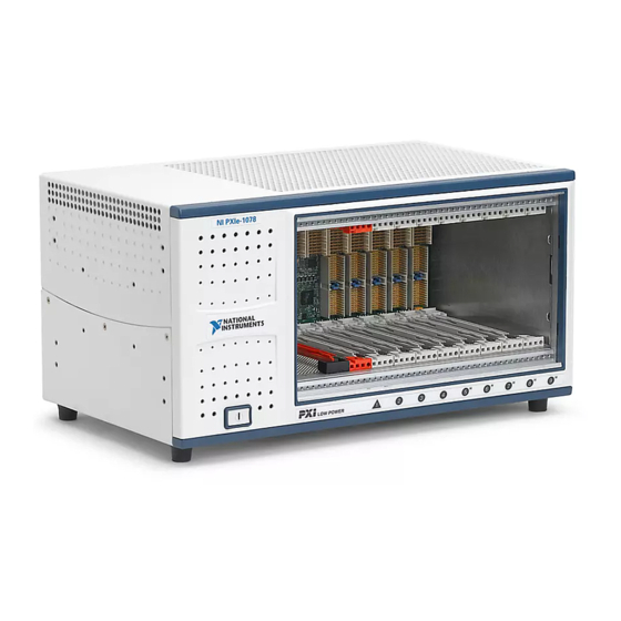
Getting Started Chassis Description Figures 1-1 and 1-2 show the key features of the NI PXIe-1078 chassis front and back panels. Figure 1-1 shows the front view of the NI PXIe-1078. Figure 1-2 shows the rear view of the NI PXIe-1078. - Page 12 1 Rear Intake Vents 5 Chassis Ground Screw 2 AC Input 6 AUTO/HIGH Fan Speed Selector Switch 3 Power Supply Fan Exhaust 7 Kensington Slot 4 Removable Feet Figure 1-2. Rear View of the NI PXIe-1078 Chassis NI PXIe-1078 User Manual ni.com...
-
Page 13: Optional Equipment
Optional EMC filler panel kits are available from National Instruments through part number 778700-01. Rack Mount Kit A rack mount kit option is available for mounting the NI PXIe-1078 chassis into a 19 in. instrument cabinet. Refer to Figure A-3, NI Chassis Rack Mount Kit Components, for more information. -
Page 14: Slot Blockers
This section provides an overview of the backplane features for the NI PXIe-1078 chassis. Interoperability with CompactPCI The design of the NI PXIe-1078 provides you the flexibility to use the following devices in a single PXI Express chassis: • PXI Express compatible products •... -
Page 15: System Controller Slot
Chapter 1 Getting Started Refer to Figure 1-4 for an overview of the NI PXIe-1078 architecture. Link #3 Link #4 PEX8614 PCIe Switch Link #2 Link #1 PCIe/PCI 32 bit, 33 MHz PCI Bus Bridge Figure 1-4. NI PXIe-1078 Backplane Architecture... -
Page 16: Hybrid Peripheral Slots
The backplane routes PXI Local Bus 6 between adjacent PXI slots. The left Local Bus 6 from slot 1 is not routed anywhere. The right Local Bus 6 from slot 9 also is not routed anywhere. NI PXIe-1078 User Manual ni.com... -
Page 17: Pxi Trigger Bus
System Reference Clock The NI PXIe-1078 chassis supplies PXI_CLK10, PXIe_CLK100, and PXIe_SYNC100 to every peripheral slot with an independent driver for each signal. An independent buffer (having a source impedance matched to the backplane and a skew of less than 500 ps between slots) drives PXI_CLK10 to each peripheral slot. - Page 18 0 1 2 3 4 5 6 7 8 9 0 1 2 3 4 5 6 7 8 9 0 1 2 3 4 5 6 7 8 9 PXIe_CLK100 PXI_CLK10 PXIe_SYNC100 Figure 1-6. System Reference Clock Default Behavior NI PXIe-1078 User Manual 1-10 ni.com...
-
Page 19: Installation And Configuration
Installation and Configuration This chapter describes how to prepare and operate the NI PXIe-1078 chassis. Before connecting the chassis to a power source, read this chapter and the Read Me First: Safety and Electromagnetic Compatibility document included with your kit. -
Page 20: Chassis Cooling Considerations
Unsuitable modifications may result in safety hazards. Chassis Cooling Considerations The NI PXIe-1078 chassis is designed to operate on a bench or in an instrument rack. Regardless of the configuration, you must provide the cooling clearances as outlined in the following sections. - Page 21 Chapter 2 Installation and Configuration 1 Air Outlets 2 Air Intake Figure 2-1. NI PXIe-1078 Module Cooling Airflow Side View © National Instruments NI PXIe-1078 User Manual...
- Page 22 I e - 1 Power Supply Cooling Intake Vent 4 Backplane Cooling Exhaust Vent 2 Module Cooling Exhaust Vent 5 Power Supply Cooling Exhaust Vent 3 Module Cooling Intake Vent Figure 2-2. NI PXIe-1078 Vents NI PXIe-1078 User Manual ni.com...
- Page 23 1.75 in. (44.45 mm) NI-PXIe-1078 1.75 in. (44.45 mm) NATIONAL INSTRUMENTS 0.625 in. (15.89 mm) 1.75 in. On Desktop (44.45 mm) In Electronics Rack 1.75 in. (44.45 mm) Figure 2-3. NI PXIe-1078 Cooling Clearances © National Instruments NI PXIe-1078 User Manual...
-
Page 24: Chassis Ambient Temperature Definition
Refer to Figure A-3, NI Chassis Rack Mount Kit Components. Note You may want to remove the feet from the NI PXIe-1078 chassis when rack mounting. To do so, remove the screws holding the feet in place. NI PXIe-1078 User Manual ni.com... -
Page 25: Connecting Safety Ground
Chapter 2 Installation and Configuration Connecting Safety Ground The NI PXIe-1078 chassis is designed with a three-position inlet that connects the Caution cord set ground line to the chassis ground. To minimize shock hazard, make sure the electrical power outlet you use to power the chassis has an appropriate earth safety ground. - Page 26 1 System Controller Front Panel Mounting Screws (4x) 3 Injector/Ejector Handle 2 NI PXI Express System Controller 4 NI PXIe-1078 Chassis Figure 2-4. Installing a PXI Express System Controller When you begin to feel resistance, push up on the injector/ejector handle to seat the system controller fully into the chassis frame.
- Page 27 - P X I e - 1 NI PXIe-1078 Chassis 2 NI PXI Express System Controller 3 Injector/Ejector Rail Figure 2-5. NI PXI Express System Controller Installed in an NI PXIe-1078 Chassis © National Instruments NI PXIe-1078 User Manual...
-
Page 28: Installing Peripheral Modules
Chapter 2 Installation and Configuration Installing Peripheral Modules The NI PXIe-1078 chassis accepts a variety of peripheral module types in Caution different slots. To prevent damage to the chassis, ensure that the peripheral module is being installed into a slot designed to accept it. Refer to Chapter 1,... -
Page 29: Power Inhibit Switch Led Indicator
Chapter 2 Installation and Configuration - P X I e - 1 NI PXIe-1078 Chassis 4 PXI Express Peripheral Module 2 NI PXI Express System Controller 5 Injector/Ejector Handle 3 Peripheral Module Front Panel Mounting Screws (2x) 6 Injector/Ejector Rail Figure 2-6. -
Page 30: Inhibit Mode Switch
Installation and Configuration Inhibit Mode Switch On the NI PXIe-1078 backplane is a four-position DIP switch (SW1). Switch 1 of SW1 controls the chassis inhibit mode. (Refer to Figure 2-7.) In its default position (OFF), the PXI Express controller controls the power supply on/off state based on the power switch on the chassis front panel. -
Page 31: Pxi Express System Configuration With Max
For more information about routing and reserving PXI triggers, refer to KnowledgeBase 3TJDOND8 at ni.com/support The configuration steps for single or multiple-chassis systems are the same. Figure 2-8. Multichassis Configuration in MAX © National Instruments 2-13 NI PXIe-1078 User Manual... -
Page 32: Pxi-1 System Configuration
Device drivers and other utility software read the pxiesys.ini file to obtain system information. For detailed information pxisys.ini about initialization files, refer to the PXI specification at www.pxisa.org NI PXIe-1078 User Manual 2-14 ni.com... -
Page 33: Using System Configuration And Initialization Files
System integrators, configuration utilities, and device drivers can use these files. .ini The capability documentation for the NI PXIe-1078 chassis is contained in file on the software media that comes with the chassis. chassis.ini The information in this file is combined with information about the system controller to create a single system initialization file called pxisys.ini... -
Page 34: Maintenance
This chapter describes basic maintenance procedures you can perform on the NI PXIe-1078 chassis. Caution Disconnect the power cable prior to servicing a NI PXIe-1078 chassis. Service Interval Clean dust from the chassis exterior (and interior) as needed, based on the operating environment. -
Page 35: Cleaning
Do not wash the front- or rear-panel connectors or switches. Cover these components while cleaning the chassis. Do not use harsh chemical cleaning agents; they may damage the chassis. Avoid chemicals that contain benzene, toluene, xylene, acetone, or similar solvents. NI PXIe-1078 User Manual ni.com... - Page 36 Specifications This appendix contains specifications for the NI PXIe-1078 chassis. Specifications are subject to change without notice. Caution Electrical AC Input Input voltage range......... 100 to 240 VAC Operating voltage range ......90 to 264 VAC Input frequency ........50/60 Hz Operating frequency range ....
- Page 37 The maximum available current from +12 V derates linearly to 16.5 A from 40 °C to 50 °C operating ambient temperature range. The -12 V regulation is ± 5% for loads of 8 A or less on the +12 V rail. NI PXIe-1078 User Manual ni.com...
- Page 38 Module cooling exhaust ......Right side, rear, and top of chassis Power supply cooling system....Forced air circulation through integrated fan Power supply cooling intake ....Front and left side of chassis Power supply cooling exhaust....Rear of chassis © National Instruments NI PXIe-1078 User Manual...
-
Page 39: Operating Environment
(Tested in accordance with IEC-60068-2-56.) Storage Environment Ambient temperature range ....-40 to 71 °C (Tested in accordance with IEC-60068-2-1 and IEC-60068-2-2. Meets MIL-PRF-28800F Class 3 limits.) Relative humidity range......10 to 95%, noncondensing (Tested in accordance with IEC-60068-2-56.) NI PXIe-1078 User Manual ni.com... - Page 40 • IEC 61010-1, EN 61010-1 • UL 61010-1, CSA 61010-1 Note For UL and other safety certifications, refer to the product label or the Online Product Certification section. © National Instruments NI PXIe-1078 User Manual...
-
Page 41: Electromagnetic Compatibility
For additional environmental information, refer to the Minimize Our Environmental Impact web page at . This page ni.com/environment contains the environmental regulations and directives with which NI complies, as well as other environmental information not included in this document. NI PXIe-1078 User Manual ni.com... - Page 42 Accepts both PXI Express and CompactPCI (PICMG 2.0 R 3.0) 3U modules. Backplane bare-board material ....UL 94 V-0 Recognized Backplane connectors ......Conforms to IEC 917 and IEC 1076-4-101, and are UL 94 V-0 rated © National Instruments NI PXIe-1078 User Manual...
- Page 43 (12 kHz-20 MHz range) Duty-factor for PXIe_CLK100....45%-55% Absolute differential voltage (When terminated with a 50 Ω load to 1.30 V or Thévenin equivalent)..400-1000 mV Note For other specifications refer to the PXI-5 PXI Express Hardware Specification. NI PXIe-1078 User Manual ni.com...
- Page 44 Polyurethane Enamel, and Polyester Urethane Powder Paint Figures A-1 and A-2 show the NI PXIe-1078 chassis dimensions. The holes shown are for the installation of the optional rack mount kits. Notice that the front and rear chassis mounting holes (size M4) are symmetrical.
- Page 45 (18.3 mm) 1.83 in. 3.13 in. 4.48 in. (46.58 mm) (113.74 mm) (79.5 mm) Module Front Panel 0.96 in. (24.38 mm) 8.43 in. (214.2 mm) Figure A-1. NI PXIe-1078 Chassis Dimensions (Front and Side) NI PXIe-1078 User Manual A-10 ni.com...
- Page 46 M4 x 0.7 0.25 in. (6.35 mm) Max, 4x 1.07 in. (27.2 mm) 6.65 in. (168.9 mm) 0.60 in. 12.8 in. (325.1 mm) (15.2 mm) Figure A-2. NI PXIe-1078 Chassis Dimensions (Bottom) © National Instruments A-11 NI PXIe-1078 User Manual...
- Page 47 Appendix A Specifications Figure A-3 shows the chassis rack mount kit components. - P X I e - 1 Front Rack Mount Kit 2 NI Chassis Figure A-3. NI Chassis Rack Mount Kit Components NI PXIe-1078 User Manual A-12 ni.com...
- Page 48 Pinouts This appendix describes the connector pinouts for the NI PXIe-1078 chassis backplane. Table B-1 shows the XP1 connector pinout for the System Controller slot. Table B-2 shows the XP2 Connector Pinout for the System Controller slot. Table B-3 shows the XP3 Connector Pinout for the System Controller slot.
- Page 49 Table B-2. XP2 Connector Pinout for the System Controller Slot 3PETp1 3PETn1 3PERp1 3PERn1 3PETp2 3PETn2 3PETp3 3PETn3 3PERp3 3PERn3 3PERp2 3PERn2 4PETp0 4PETn0 4PERp0 4PERn0 4PETp1 4PETn1 4PETp2 4PETn2 4PERp2 4PERn2 4PERp1 4PERn1 4PETp3 4PETn3 4PERp3 4PERn3 NI PXIe-1078 User Manual ni.com...
- Page 50 2PETp3 2PETn3 3PETp0 3PETn0 3PERp0 3PERn0 2PERp3 2PERn3 Table B-4. XP4 Connector Pinout for the System Controller Slot 5Vaux SYSEN# WAKE# ALERT# PXI_TRIG3 PXI_TRIG4 PXI_TRIG5 PXI_TRIG6 PXI_TRIG2 PXI_STAR PXI_CLK10 PXI_TRIG1 PXI_TRIG0 PXI_TRIG7 PXI_LBR6 © National Instruments NI PXIe-1078 User Manual...
- Page 51 AD[19] C/BE[3]# IDSEL AD[23] AD[22] AD[26] V(I/O) AD[25] AD[24] AD[30] AD[29] AD[28] AD[27] REQ# 3.3 V AD[31] BRSVP1A5 BRSVP1B5 RST# GNT# IPMB_PWR HEALTHY# V(I/O) INTP INTS INTA# INTB# INTC# INTD# -12 V TRST# +12 V NI PXIe-1078 User Manual ni.com...
- Page 52 Table B-7. XP4 Connector Pinout for the PXI Express/Hybrid Slot 5 Vaux SYSEN# WAKE# ALERT# 12 V 12 V 3.3 V 3.3 V 3.3 V PXI_TRIG3 PXI_TRIG4 PXI_TRIG5 PXI_TRIG6 PXI_TRIG2 ATNLED PXI_STAR PXI_CLK10 PXI_TRIG1 PXI_TRIG0 ATNSW# PXI_TRIG7 PXI_LBL6 PXI_LBR6 © National Instruments NI PXIe-1078 User Manual...
- Page 53 Technical Support and Professional Services Log in to your National Instruments User Profile to get ni.com personalized access to your services. Visit the following sections of for technical support and professional services: ni.com • Support—Technical support at includes the ni.com/support following resources: –...
- Page 54 Appendix C Technical Support and Professional Services • System Integration—If you have time constraints, limited in-house technical resources, or other project challenges, National Instruments Alliance Partner members can help. To learn more, call your local NI office or visit ni.com/alliance •...
- Page 55 Symbols ° Degrees. ≥ Equal or greater than. ≤ Equal or less than. Percent. Amperes. Alternating current. ANSI American National Standards Institute. Auto Automatic fan speed control. American Wire Gauge. © National Instruments Corporation NI PXIe-1078 User Manual...
- Page 56 A method of propagating signals along a bus, in which the devices are prioritized on the basis of their position on the bus. DB-9 A 9-pin D-SUB connector. Direct current. Declaration of Conformity. D-SUB Subminiature D connector. NI PXIe-1078 User Manual ni.com...
- Page 57 Hours. Hertz; cycles per second. International Electrotechnical Commission; an organization that sets international electrical and electronics standards. IEEE Institute of Electrical and Electronics Engineers. Mainframe peak current. © National Instruments Corporation NI PXIe-1078 User Manual...
- Page 58 Meters. Megahertz. One million Hertz; one Hertz equals one cycle per second. Miles. Milliseconds. MTBF Mean time between failure. MTTR Mean time to repair. NI PXIe-1078 User Manual ni.com...
- Page 59 PXI system in that it performs the system controller functions, including clock sourcing and arbitration for data transfers across the backplane. Installing such a device into any other slot can damage the device, the PXI backplane, or both. © National Instruments Corporation NI PXIe-1078 User Manual...
- Page 60 The PXI backplane specification defines implementation guidelines for PXI_CLK10. System Timing slot This slot is located at slot 4 and has dedicated trigger lines to other slots. Transistor-transistor logic. Underwriter’s Laboratories. Volts. Volts alternating current. Peak-to-peak voltage. Watts. NI PXIe-1078 User Manual ni.com...
- Page 61 Index configuration. See installation, configuration, and operation AC power cables (table), 1-2 cooling air cooling of NI PXIe-1078, 2-2 air intake (figure), 2-3 filler panel installation, 2-6 backplane setting fan speed, 2-6 hybrid peripheral slots, 1-8 slot blocker installation, 2-6...
- Page 62 PXI Express configuration in MAX, 2-13 module cooling air intake (figure), 2-3 PXI Express system controller installed in optional equipment, 1-5 a NI PXIe-1078 chassis (figure), 2-9 rack mounting, 2-6 PXI-1 configuration in MAX, 2-14 rear view, 1-4 rack mounting, 2-6...
- Page 63 PXI Express peripheral slots description, 1-8 dimensions (figure), A-10, A-11 PXI Express system controller, 2-7 electrical figure, 2-8 AC input, A-1 installing in a NI PXIe-1078 chassis DC output, A-2 (figure), 2-9 electromagnetic compatibility, A-6 PXI local bus, routing, 1-8 environmental...
- Page 64 (figure), 1-10 specifications, A-8 technical support, C-1 testing power up, 2-7 training and certification (NI resources), C-1 trigger bus, 1-9 troubleshooting (NI resources), C-1 unpacking the NI PXIe-1078 chassis, 1-1 Web resources, C-1 WEEE information, A-7 NI PXIe-1078 User Manual ni.com...
Need help?
Do you have a question about the NI PXIe-1078 and is the answer not in the manual?
Questions and answers