Table of Contents
Advertisement
Quick Links
GETTING STARTED GUIDE
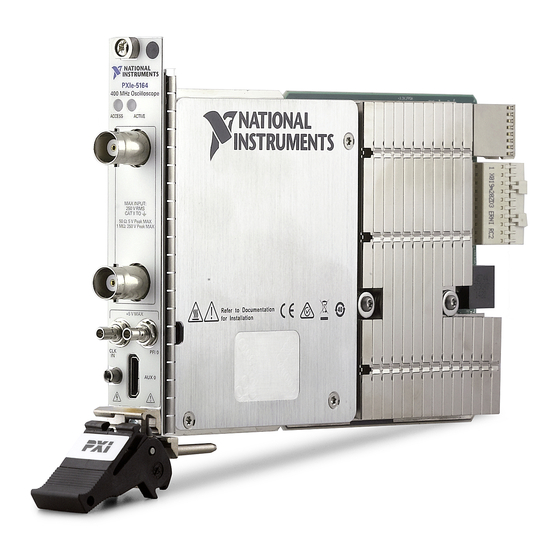
PXIe-5164
PXIe, 400 MHz, 1 GS/s, 14-bit PXI Oscilloscope
Note
Before you begin, install and configure your chassis and controller.
This document explains how to install, configure, and test the PXIe-5164. The PXIe-5164 is a
1 GS/s reconfigurable oscilloscope with a user-programmable FPGA.
To access PXIe-5164 documentation, navigate to Start»All Programs»National
Instruments»Reconfigurable Oscilloscopes»Reconfigurable Oscilloscopes Documentation
or Start»All Programs»National Instruments»NI-SCOPE»NI-SCOPE Documentation.
Contents
Verifying the System Requirements..........................................................................................2
Unpacking the Kit..................................................................................................................... 2
Other Equipment....................................................................................................................... 3
Preparing the Environment....................................................................................................... 4
Choosing the Software.............................................................................................................. 4
Software Options...............................................................................................................4
Comparison of Software Features.....................................................................................5
Installing the Software.............................................................................................................. 6
Installing the PXIe-5164........................................................................................................... 7
PXIe-5164 Front Panel and Pinout ........................................................................................ 10
PXIe-5164 SCB-19 Pinout..............................................................................................13
PXIe-5164 Mini-HDMI Breakout Cable to 6 BNC Pinout.............................................14
Configuring the PXIe-5164 in MAX...................................................................................... 15
PXIe-5164 Self-Calibration.................................................................................................... 16
Running Self-Calibration................................................................................................ 16
First Measurements................................................................................................................. 17
Making a Measurement with InstrumentStudio..............................................................17
Making a Measurement with LabVIEW......................................................................... 17
Making a Measurement with Instrument Design Libraries............................................ 18
PXIe-5164 Compensating Passive Probes...................................................................... 18
Troubleshooting...................................................................................................................... 20
Why Is the ACCESS LED Off When the Chassis Is On?...............................................20
What Should I Do if the PXIe-5164 Doesn't Appear in MAX?......................................21
What Should I Do if the PXIe-5164 Fails the Self-Test or Self-Calibration?.................21
Where to Go Next................................................................................................................... 22
Worldwide Support and Services............................................................................................ 23
Advertisement
Table of Contents

Related Manuals for National Instruments PXIe-5164


Summary of Contents for National Instruments PXIe-5164
-
Page 1: Table Of Contents
Note Before you begin, install and configure your chassis and controller. This document explains how to install, configure, and test the PXIe-5164. The PXIe-5164 is a 1 GS/s reconfigurable oscilloscope with a user-programmable FPGA. To access PXIe-5164 documentation, navigate to Start»All Programs»National Instruments»Reconfigurable Oscilloscopes»Reconfigurable Oscilloscopes Documentation... -
Page 2: Verifying The System Requirements
(ADEs). Unpacking the Kit Refer to the following figure to identify the contents of the PXIe-5164 kit. Figure 1. PXIe-5164 Kit Contents 1. PXIe-5164 3. PXIe-5164 Getting Started Guide (this document) 2. -
Page 3: Other Equipment
Other Equipment There are several required items not included in your device kit that you need to operate the PXIe-5164. Your application may require additional items not included in your kit to install or operate your device. Required Items •... -
Page 4: Preparing The Environment
30 A RMS, 100 MHz current probe Visit ni.com for more information about these additional items. Preparing the Environment Ensure that the environment in which you are using the PXIe-5164 meets the following specifications. Temperature Operating 0 °C to 50 °C Storage -40 °C to 71 °C... -
Page 5: Comparison Of Software Features
Feature NI-SCOPE Instrument Design Libraries Customization of onboard Yes, using the Yes, using the LabVIEW FPGA FPGA instrument driver Module FPGA extensions Source availability Closed source Open source LabVIEW support PXIe-5164 Getting Started Guide | © National Instruments | 5... -
Page 6: Installing The Software
LabVIEW Instrument Design Libraries for Reconfigurable Oscilloscopes Download the latest versions of NI-SCOPE and/or LabVIEW Instrument Design Libraries for Reconfigurable Oscilloscopes, extract the downloaded files, and run the executable ( ) file(s). .exe 6 | ni.com | PXIe-5164 Getting Started Guide... -
Page 7: Installing The Pxie-5164
Note to Users included with the module to ensure that the device can cool itself effectively. This document is also available at ni.com/manuals. The PXIe-5164 is a single-slot module with one backplane connector. The module may be installed into any PXI Express-compatible slot. - Page 8 5. PXI Express Peripheral Slot 3. PXI Express Hybrid Peripheral Slot PXIe-5164 modules can be placed in PXI Express peripheral slots, PXI Express hybrid peripheral slots, or PXI Express system timing slots. Touch any metal part of the chassis to discharge static electricity.
- Page 9 13. Cover all empty slots using EMC filler panels or fill using slot blockers to maximize cooling air flow, depending on your application. 14. Power on the chassis. Related Information Why Is the ACCESS LED Off When the Chassis Is On? on page 20 PXIe-5164 Getting Started Guide | © National Instruments | 9...
-
Page 10: Pxie-5164 Front Panel And Pinout
ACTIVE CH 0 MAX INPUT: 250 V RMS CAT II TO 50 Ω: 5 V Peak MAX 1 MΩ: 250 V Peak MAX CH 1 +5 V MAX PFI 0 AUX 0 10 | ni.com | PXIe-5164 Getting Started Guide... - Page 11 Detected an overheating or overpowering error. Note Certain driver interactions may cause the Active LED to flash red. An error condition does not exist unless the Active LED remains red. PXIe-5164 Getting Started Guide | © National Instruments | 11...
- Page 12 AUX 0/PFI 0 Bidirectional PFI line AUX 0/PFI 1 Bidirectional PFI line Ground reference for signals AUX 0/PFI 2 Bidirectional PFI line AUX 0/PFI 3 Bidirectional PFI line Ground reference for signals 12 | ni.com | PXIe-5164 Getting Started Guide...
-
Page 13: Pxie-5164 Scb-19 Pinout
You can use the SCB-19 connector block to connect digital signals to the AUX 0 connector on the PXIe-5164 front panel. Refer to the following figure and table for information about the SCB-19 signals when connected to the AUX 0 front panel connector. -
Page 14: Pxie-5164 Mini-Hdmi Breakout Cable To 6 Bnc Pinout
You can use the Mini-HDMI Breakout Cable to 6 BNC to connect digital signals to the AUX 0 connector on the PXIe-5164 front panel. Refer to the following figure and table for information about the Mini-HDMI Breakout Cable to 6 BNC signals when connected to the AUX 0 front panel connector. -
Page 15: Configuring The Pxie-5164 In Max
MAX lists all modules installed in the chassis. Your default names may vary. Note PXIe-5164 modules appear as NI-RIO devices in the list. If you do not see your module listed, press <F5> to refresh the list of installed modules. If the module is still not listed, power off the system, ensure the module is correctly installed, and restart. -
Page 16: Pxie-5164 Self-Calibration
In these cases, you can improve performance by loading your image and configuring the PXIe-5164 before warm-up time begins. PXIe-5164 modules are externally calibrated at the factory, but for optimal performance, use self-calibration in any of the following situations: •... -
Page 17: First Measurements
When the two-year external calibration interval expires, an external calibration is required to ensure performance that is within specification over the subsequent two years. Related Information What Should I Do if the PXIe-5164 Fails the Self-Test or Self-Calibration? on page 21 First Measurements Making a Measurement with InstrumentStudio Connect CH 0 to an input signal. -
Page 18: Making A Measurement With Instrument Design Libraries
Select File»Create Project. On the left side of the Create Project window, select Oscilloscopes. On the right side of the Create Project window, select the Stream to Host (PXIe-5164) sample project and click Next. Specify a name, location, and device target for the project in the Create Project window and click Finish. - Page 19 PFI • A probe tip–to-BNC (m) adapter The PXIe-5164 can output a 1 kHz square wave that you can use to compensate passive probes. To compensate a passive probe, complete the following steps: Connect the BNC end of the probe to an input channel of your oscilloscope.
-
Page 20: Troubleshooting
LED. Notice Apply external signals only while the PXIe-5164 is powered on. Applying external signals while the module is powered off may cause damage. Disconnect any signals from the module front panels. -
Page 21: What Should I Do If The Pxie-5164 Doesn't Appear In Max
Verify that the module appears in MAX. Reset the module in MAX and perform a self-test. What Should I Do if the PXIe-5164 Doesn't Appear in MAX? In the MAX configuration tree, expand Devices and Interfaces. -
Page 22: Where To Go Next
Device information is also located in the NI High-Speed Digitizers Help. † NI High-Speed Use this help file to learn how to operate the PXIe-5164 using the Digitizers Help NI-SCOPE soft front panel and device driver. This help file also includes device information and programming information. -
Page 23: Worldwide Support And Services
1 866 ASK MYNI (275 6964). For support outside the United States, visit the Worldwide Offices section of ni.com/niglobal access the branch office websites, which provide up-to-date contact information. PXIe-5164 Getting Started Guide | © National Instruments | 23... - Page 24 NI trademarks. Other product and company names mentioned herein are trademarks or trade names of their respective companies. For patents covering NI products/technology, refer to the appropriate location: Help»Patents in your software, the file on your media, or the National Instruments Patent Notice at . You can find patents.txt ni.com/patents...
Need help?
Do you have a question about the PXIe-5164 and is the answer not in the manual?
Questions and answers