ABB RER620 Technical Manual
Advanced recloser protection and control
Hide thumbs
Also See for RER620:
- Product manual (44 pages) ,
- Applications manual (90 pages) ,
- Manual (60 pages)

Related Manuals for ABB RER620


Summary of Contents for ABB RER620
- Page 1 ® Relion Protection and Control Advanced Recloser Protection and Control RER620 Technical Manual...
- Page 3 Document ID: 1MAC309294-MB Issued: 7/20/2017 Revision:F Product version: 1.3 © Copyright 2017 ABB. All rights reserved.
- Page 4 Copyright This document and parts thereof must not be reproduced or copied without written permission from ABB, and the contents thereof must not be imparted to a third party, nor used for any unauthorized purpose. The software or hardware described in this document is furnished under a license and may be used, copied, or disclosed only in accordance with the terms of such license.
- Page 5 This document has been carefully checked by ABB but deviations cannot be completely ruled out. In case any errors are detected, the reader is kindly requested to notify the manufacturer.
- Page 6 (Low-voltage directive 2006/95/EC). This conformity is the result of tests conducted by ABB in accordance with the product standards EN 50263 and EN 60255-26 for the EMC directive, and with the product standards EN 60255-6 and EN 60255-27 for the low voltage directive.
-
Page 7: Table Of Contents
Symbols and conventions ..............19 Safety indication symbols..............19 Manual conventions ................20 Functions, codes and symbols............21 Section 2 RER620 overview............... 25 Overview ....................25 Product series version history ............25 PCM600 and relay connectivity package version ......25 Local HMI ....................26 LCD .................... - Page 8 QTY_GOOD function block ............... 62 Function block ................62 Functionality ................. 62 Signals ..................63 QTY_BAD function block..............63 Function block ................63 Functionality ................. 63 Signals ..................63 T_HEALTH function block ..............64 Function block ................64 RER620 Technical Manual...
- Page 9 Function block................83 Functionality................. 83 Operation principle ............... 83 Measurement modes ..............87 Timer characteristics ..............87 Application ................... 89 Signals ..................94 Settings ..................95 Monitored data ................98 Technical data................99 Technical revision history............100 RER620 Technical Manual...
- Page 10 Measurement modes ..............148 Timer characteristics ..............149 Directional ground-fault characteristics ........151 Application.................. 161 Signals ..................163 Settings ..................164 Monitored data ................169 Technical data................170 Sensitive earth-fault protection 50SEF..........170 Identification ................170 Function block ................171 RER620 Technical Manual...
- Page 11 Function block................184 Functionality................184 Operation principle ..............184 Application ................. 186 Signals ..................187 Settings ..................187 Monitored data ................187 Technical data................188 Cold load timers ................... 188 Voltage protection ................188 Single-phase overvoltage protection 59.......... 188 RER620 Technical Manual...
- Page 12 Positive sequence overvoltage protection 59PS ......210 Identification ................210 Function block ................210 Functionality ................210 Operation principle ..............210 Application.................. 211 Signals ..................211 Settings ..................212 Technical data................212 Negative sequence overvoltage protection 47 ........ 213 Identification ................213 RER620 Technical Manual...
- Page 13 Application ................. 229 Signals ..................233 Settings ..................234 Monitored data ................234 Technical data................234 Other protection functions available in RER620........235 Circuit breaker failure protection 50BFT ......... 235 Identification................235 Function block................235 Functionality................235 Operation principle ..............235 Application .................
- Page 14 Settings ..................262 Monitored data ................263 Technical data................263 Directional negative/zero sequence power protection 32N ..... 263 Identification ................263 Function block ................264 Functionality ................264 Operation principle ..............264 Application.................. 270 Signals ..................270 RER620 Technical Manual...
- Page 15 Monitored data ................320 Technical data................. 323 Synch-check/voltage check 25............. 323 Identification ..................323 Function block ................. 323 Functionality ..................323 Operation principle ................324 Application..................331 Signals .................... 333 Settings ................... 334 Monitored data ................335 RER620 Technical Manual...
- Page 16 ..............364 Remaining life of the circuit breaker........... 365 Circuit breaker spring charged indication ........367 Gas pressure supervision ............367 Application..................368 Signals..................... 372 Settings ................... 374 Monitored data ................375 Technical data ................. 375 RER620 Technical Manual...
- Page 17 Identification................398 Function block................398 Signals ..................398 Settings ..................398 Monitored data ................399 Technical data................399 Ground voltage VG ................. 399 Identification................399 Function block................399 Signals ..................399 Settings ..................400 Monitored data ................400 RER620 Technical Manual...
- Page 18 Recorded analog inputs ............. 413 Triggering alternatives..............413 Length of recordings................ 415 Sampling frequencies..............415 Uploading of recordings ............. 415 Deletion of recordings ..............416 Storage mode................416 Pre-trigger and post-trigger data ..........417 Operation modes................ 417 RER620 Technical Manual...
- Page 19 Loss of UPS input power alarm..........426 Battery management..............427 Auxiliary Power Supply .............. 428 Actuator Drive Power Source (Boost Supply) ......428 Heater control switch ..............428 RER620 power................429 RS485 communications ............. 429 Connections ..................430 Signals .................... 431 CVD Voltage Clamping ..............431 Settings ...................
- Page 20 Voltage based inverse definite minimum time characteristics ....534 IDMT curves for overvoltage protection .......... 534 Standard inverse-time characteristics for overvoltage protection ................... 537 User programmable inverse-time characteristics for overvoltage protection..............540 IDMT curve saturation of overvoltage protection ....... 541 RER620 Technical Manual...
- Page 21 Rear communication modules............556 COMB022/23A jumper locations and connections ....557 Section 13 Technical data ..............563 Section 14 Relay and functionality tests..........569 Section 15 Applicable standards and regulations ......571 Section 16 Glossary ................573 RER620 Technical Manual...
- Page 22 Section 1MAC309294-MB F RER620 Technical Manual...
-
Page 23: Introduction
The system engineer must have a thorough knowledge of protection systems, protection equipment, protection functions and the configured functional logic in the relays. The installation and commissioning personnel must have a basic knowledge in handling electronic equipment. RER620 Technical Manual... -
Page 24: Product Documentation
The manual can also be used when calculating settings. The technical manual contains application and functionality descriptions and lists function blocks, logic diagrams, input and output signals, setting parameters and technical data RER620 Technical Manual... -
Page 25: Document Revision History
Content updated Download the latest documents from the ABB web site http://www.abb.com/substationautomation. 1.3.3 Related documentation Product series- and product-specific manuals can be downloaded from the ABB web site http://www.abb.com/substationautomation. Symbols and conventions 1.4.1 Safety indication symbols The electrical warning icon indicates the presence of a hazard which could result in electrical shock. -
Page 26: Manual Conventions
• Analog inputs to protection functions are shown in the technical manual for clarity however these inputs and connections do not appear in the application logic. The connection of these analog signals is fixed internally to the corresponding function blocks and cannot be altered by users. RER620 Technical Manual... -
Page 27: Functions, Codes And Symbols
Function block as it appears in the manual (left) and in the ACT (right) 1.4.3 Functions, codes and symbols All available functions are listed in the table. All of them may not be applicable to all products. RER620 Technical Manual... - Page 28 Section 1 1MAC309294-MB F Introduction Table 1: RER620 functions, codes and symbols Function IEC61850 IEC60617 ANSI/C37.2 Current Protection Single-phase non-directional time overcurrent protection with 1-ph trip option, low stage SPHLPTOC1 3I>(1) Single-phase non-directional time overcurrent protection with 1-ph trip option, high stage 1 SPHLPTOC2 3I>(2)
- Page 29 Other Functions Battery voltage, current. Test the battery ZBAT1 Universal Power Drive XGGIO115 X115(UPD) X115(UPD) Programmable buttons (16 buttons) FKEYGGIO1 FKEYGGIO1 FKEYGGIO1 Move function block (8 outputs) MVGAPC1 MVGAPC1 MVGAPC1 Move function block (8 outputs) MVGAPC2 MVGAPC2 MVGAPC2 RER620 Technical Manual...
- Page 30 UDFCNT7 UDFCNT7 Multipurpose generic up-down counter UDFCNT8 UDFCNT8 UDFCNT8 Multipurpose generic up-down counter UDFCNT9 UDFCNT9 UDFCNT9 Multipurpose generic up-down counter UDFCNT10 UDFCNT10 UDFCNT10 Multipurpose generic up-down counter UDFCNT11 UDFCNT11 UDFCNT11 Multipurpose generic up-down counter UDFCNT12 UDFCNT12 UDFCNT12 RER620 Technical Manual...
-
Page 31: Rer620 Overview
RER620 overview Overview RER620 is a product family of relays designed for protection, control, measurement and supervision of utility substations and industrial switchgear and equipment. The design of the relays has been guided by the IEC 61850 standard for communication and interoperability of substation automation devices. -
Page 32: Local Hmi
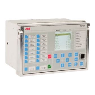
Section 2 1MAC309294-MB F RER620 overview Local HMI Figure 3: LHMI The LHMI of the relay contains the following elements: • Display • Buttons • LED indicators • Communication port The LHMI is used for setting, monitoring and controlling. 2.2.1 The LHMI includes a graphical LCD that supports two character sizes. -
Page 33: Leds
Section 2 1MAC309294-MB F RER620 overview Table 2: Characters and rows on the view Character size Rows in view Characters on row Large, variable width (13x14 4 rows min 8 pixels) 8 rows with large screen The display view is divided into four basic areas. -
Page 34: Web Hmi
Section 2 1MAC309294-MB F RER620 overview Figure 5: LHMI keypad with object control, navigation and command push-buttons and RJ-45 communication port Web HMI The WHMI enables the user to access the relay via a web browser. The supported web browser versions are Internet Explorer 9.0, 10.0 and 11.0. -
Page 35: Authorization
Section 2 1MAC309294-MB F RER620 overview Figure 6: Example view of the WHMI The WHMI can be accessed locally and remotely. • Locally by connecting your laptop to the relay via the front communication port. • Remotely over LAN/WAN. Authorization The user categories have been predefined for the LHMI and the WHMI, each with different rights and default passwords. -
Page 36: Communication
Section 2 1MAC309294-MB F RER620 overview User authorization is disabled by default but WHMI always uses authorization. Table 3: Predefined user categories Username User rights VIEWER Read only access OPERATOR • Selecting remote or local state with (only locally) •... -
Page 37: Basic Functions
Phase A Voltage phasor magnitude correction of an external voltage transformer Amplitude corr. B 0.500...1.500 0.00 1.000 Phase B Voltage phasor magnitude correction of an external voltage transformer Amplitude corr. C 0.500...1.500 0.00 1.000 Phase C Voltage phasor magnitude correction of an external voltage transformer RER620 Technical Manual... - Page 38 Alarm mode for LED 4 1=Follow-F 2=Latched-S 3=LatchedAck-F-S Description Alarm LEDs LED 4 Description of alarm Alarm LED mode 0=Follow-S 0=Follow-S Alarm mode for LED 5 1=Follow-F 2=Latched-S 3=LatchedAck-F-S Description Alarm LEDs LED 5 Description of alarm RER620 Technical Manual...
- Page 39 0=False 1=True Disable authority 1=True Local viewer Set password Local operator Set password Local engineer Set password Local admin Set password Remote viewer Set password Remote operator Set password Remote engineer Set password Remote admin Set password RER620 Technical Manual...
- Page 40 Blocking mode 1=Freeze timer 1=Freeze timer Behavior for function BLOCK inputs 2=Block all 3=Block trip Bay name RER620 Bay name in system SG follow input 0=False 0=False Enable setting group change to follow the input state 1=True Phase Order Mode...
- Page 41 Web HMI login timeout SLD symbol format 1=IEC 2=ANSI Single Line Diagram symbol format 2=ANSI Table 16: IEC 61850-8-1 MMS: Non group settings Parameter Values (Range) Unit Step Default Description Unit mode 1=Primary 0=Nominal IEC 61850-8-1 unit mode 0=Nominal 2=Primary-Nominal RER620 Technical Manual...
- Page 42 1=32 bit AI; 2=16 bit AI; 3=32 bit AI without flag; 4=16 bit AI without flag. Default Var Obj 32 1...4 1=32 bit AI event; 2=16 bit AI event; 3=32 bit AI event with time; 4=16 bit AI event with time. RER620 Technical Manual...
- Page 43 Maximum number of Modbus TCP/IP clients TCPWriteAuthority 0=No clients 2=All clients Write authority 1=Reg. clients setting for Modbus 2=All clients TCP/IP clients EventID 0=Address 0=Address Event ID selection 1=UID TimeFormat 0=UTC 1=Local Time format for 1=Local Modbus time stamps RER620 Technical Manual...
- Page 44 7 CtlStructPWd8 **** Password for Modbus control struct 8 Internal Overflow 0=False 0=False Modbus Internal 1=True Overflow: TRUE-System level overflow occurred (indication only) 1. The amount of available control structures may vary depending on the relay type. RER620 Technical Manual...
- Page 45 3=Fiber light ON star 4=Fiber light OFF star Serial mode 1=RS485 2Wire 1=RS485 2Wire Serial mode for COM2 2=RS485 4Wire 3=RS232 no handshake 4=RS232 with handshake CTS delay 0...60000 CTS delay for COM2 RTS delay 0...60000 RTS delay for COM2 RER620 Technical Manual...
- Page 46 Section 3 1MAC309294-MB F Basic functions Parameter Values (Range) Unit Step Default Description Baud rate 1=300 6=9600 Baud rate for COM2 2=600 3=1200 4=2400 5=4800 6=9600 7=19200 8=38400 9=57600 10=115200 RER620 Technical Manual...
- Page 47 "DST offset" to 0, the system time will be the same as the sync source. 2. If the time sync source is set to UTC, we can set the following values, Local time offset = -300 (for Eastern time zone) DST on time = 2:00 RER620 Technical Manual...
- Page 48 DST off day = Sun These settings will take care of all the DST time changes automatically, no need to adjust every year. Table 23: Generic timers, TPGAPC1...4 Parameter Values (Range) Unit Step Default Description Pulse time 0...60000 Minimum pulse time RER620 Technical Manual...
- Page 49 Connectors 1-2 X110-Input 2 BOOLEAN Connectors 3-4 X110-Input 3 BOOLEAN Connectors 5-6c X110-Input 4 BOOLEAN Connectors 7-6c X110-Input 5 BOOLEAN Connectors 8-9c X110-Input 6 BOOLEAN Connectors 10-9c X110-Input 7 BOOLEAN Connectors 11-12c X110-Input 8 BOOLEAN Connectors 13-12c RER620 Technical Manual...
- Page 50 Input 4 filter time 5...1000 Connectors 5-6 Input 1 inversion 0=False 0=False Connectors 1-2c 1=True Input 2 inversion 0=False 0=False Connectors 3-2c 1=True Input 3 inversion 0=False 0=False Connectors 4-2c 1=True Input 4 inversion 0=False 0=False Connectors 5-6 1=True RER620 Technical Manual...
-
Page 51: Self-Supervision
The self-supervision signal output operates on the closed circuit principle. Under normal conditions the relay is energized and the contact gap 3-5 in slot X100 is closed. If the auxiliary power supply fail or an internal fault is detected, the contact gap 3-5 is opened. RER620 Technical Manual... -
Page 52: Warnings
LHMI. The fault indication message can be manually cleared If a fault appears, record the name and code so that it can be provided to ABB customer service. - Page 53 Card in slot X110 is wrong type, is missing or does not belong Conf. error,X110 to the original composition. Internal Fault Card in slot X120 is wrong type, is missing or does not belong Conf. error,X120 to the original composition. RER620 Technical Manual...
- Page 54 FPGA error Internal Fault Error in the RTC on the CPU card. RTC error Internal Fault UPD card error in X115 UPD card error in X115 Internal Fault UPD self-check fail in X115 UPD self-check fail in X115 RER620 Technical Manual...
- Page 55 UPS Command failure in X115 UPS Command failure in X115 Warning Breaker Operation Failure, possibly due to incorrect Breaker Operation Failure setting for UPD or UPD profile setting. For further information on warning indications, see the operation manual. RER620 Technical Manual...
-
Page 56: Led Indication Control
DNP3 can be used as a time synchronization source. When the SNTP server IP setting is changed, the relay must be rebooted to activate the new IP address. The SNTP server IP settings are normally defined in the engineering phase via the SCL file. RER620 Technical Manual... -
Page 57: Parameter Setting Groups
IRIG-B sync source is selected and the IRIG-B signal source is connected. ABB has tested the IRIG-B with the following clock masters: • Tekron TTM01 GPS clock with IRIG-B output • Meinberg TCG511 controlled by GPS167 •... -
Page 58: Recorded Data
Enable/Disable and BLOCK input that can be used for blocking the recording triggering by using logic, for example during the auto-reclosing sequence. The recorded data can be separately cleared with parameters in the Clear menu. The data recorded depend on the product and the standard configuration. RER620 Technical Manual... - Page 59 87LOZREF duration FLOAT32 0.00...100.00 87LOZREF Pickup duration 51P duration FLOAT32 0.00...100.00 51P Pickup duration 50P-3 duration FLOAT32 0.00...100.00 50P-3 Pickup duration 67/51P duration FLOAT32 0.00...100.00 67/51P Pickup duration 67/50P-1 duration FLOAT32 0.00...100.00 67/50P-1 Pickup duration RER620 Technical Manual...
-
Page 60: Non-Volatile Memory
• Trip circuit lockout • Counter values Binary input 3.8.1 Binary input filter time The filter time eliminates debounces and short disturbances on a binary input. The filter time is set for each binary input of the relay. RER620 Technical Manual... -
Page 61: Binary Input Inversion
When a binary input is inverted, the state of the input is TRUE (1) when no control voltage is applied to its terminals. Accordingly, the input state is FALSE (0) when a control voltage is applied to the terminals of the binary input. RER620 Technical Manual... -
Page 62: Oscillation Suppression
VALID output indicates invalid status. The IN input is defined in the GOOSE configuration and can always be seen in SMT sheet. Settings The GOOSE function blocks do not have any parameters available in LHMI or PCM600. RER620 Technical Manual... -
Page 63: Goosercv_Bin Function Block
BOOLEAN Output signal VALID BOOLEAN Output signal 3.9.2 GOOSERCV_DP function block 3.9.2.1 Function block GOOSERCV_DP VALID Figure 10: Function block 3.9.2.2 Functionality The GOOSERCV_DP function is used to connect the GOOSE double binary inputs to the application. RER620 Technical Manual... -
Page 64: Signals
The GOOSERCV_MV function is used to connect the GOOSE measured value inputs to the application. 3.9.3.3 Signals Table 43: GOOSERCV_MV Input signals Name Type Default Description FLOAT32 Input signal Table 44: GOOSERCV_MV Output signals Name Type Description FLOAT32 Output signal VALID BOOLEAN Output signal RER620 Technical Manual... -
Page 65: Goosercv_Int8 Function Block
The GOOSERCV_INTL function is used to connect the GOOSE double binary input to the application and extracting single binary position signals from the double binary position signal. The OP output signal indicates that the position is open. Default value (0) is used if VALID output indicates invalid status. RER620 Technical Manual... -
Page 66: Signals
The ANG output passes the received GOOSE (angle) value for the application. Default value (0) is used if VALID output indicates invalid status. 3.9.6.3 Signals Table 49: GOOSERCV_CMV Input signals Name Type Default Description MAG_IN FLOAT32 Input signal (amplitude) ANG_IN FLOAT32 Input signal (angle) RER620 Technical Manual... -
Page 67: Goosercv_Enum Function Block
GOOSERCV_ENUM Input signals Name Type Default Description Enum Input signal Table 52: GOOSERCV_ENUM Output signals Name Type Description Enum Output signal VALID BOOLEAN Output signal 3.9.8 GOOSERCV_INT32 function block 3.9.8.1 Function block GOOSERCV_INT32 VALID Figure 16: Function block RER620 Technical Manual... -
Page 68: Functionality
(simple and even combined) signal has quality which can be evaluated. The OUT output indicates quality good of the input signal. Input signals that have no quality bits set or only test bit is set, will indicate quality good status. RER620 Technical Manual... -
Page 69: Signals
The OUT output indicates quality bad of the input signal. Input signals that have any other than test bit set, will indicate quality bad status. 3.10.2.3 Signals Table 57: QTY_BAD Input signals Name Type Default Description Input signal Table 58: QTY_BAD Output signals Name Type Description BOOLEAN Output signal RER620 Technical Manual... -
Page 70: T_Health Function Block
Name Type Default Description Input signal Table 60: T_HEALTH Output signals Name Type Description BOOLEAN Output signal WARNING BOOLEAN Output signal ALARM BOOLEAN Output signal 3.10.4 T_F32_INT8 function block Function block T_F32_INT8 INT8 Figure 20: Function block RER620 Technical Manual... -
Page 71: Functionality
Manager (PCM600). 3.11 Configurable logic blocks 3.11.1 Standard configurable logic blocks 3.11.1.1 OR function block Function block Figure 21: Function blocks 3.11.1.2 Functionality OR and OR6 are used to form general combinatory expressions with Boolean variables. RER620 Technical Manual... - Page 72 OR Output signals Name Type Description BOOLEAN Output signal Table 66: OR6 Output signals Name Type Description BOOLEAN Output signal Settings The function does not have any parameters available in LHMI or Protection and Control Relay Manager (PCM600). RER620 Technical Manual...
-
Page 73: And Function Block
AND and AND6 are used to form general combinatory expressions with Boolean variables. The default value in all inputs is logical true, which makes it possible to use only the required number of inputs and leave the rest disconnected. AND has two inputs and AND6 has six inputs. RER620 Technical Manual... -
Page 74: Xor Function Block
The function does not have any parameters available in LHMI or Protection and Control Relay Manager (PCM600). 3.11.1.4 XOR function block Function block Figure 23: Function block Functionality The exclusive OR function XOR is used to generate combinatory expressions with Boolean variables. RER620 Technical Manual... -
Page 75: Not Function Block
NOT Input signals Name Type Default Description BOOLEAN Input signal Table 74: NOT Output signals Name Type Description BOOLEAN Output signal Settings The function does not have any parameters available in LHMI or Protection and Control Relay Manager (PCM600). RER620 Technical Manual... -
Page 76: Max3 Function Block
MAX3 Output signals Name Type Description FLOAT32 Output signal Settings The function does not have any parameters available in LHMI or Protection and Control Relay Manager (PCM600). 3.11.1.7 MIN3 function block Function block MIN3 Figure 26: Function block RER620 Technical Manual... -
Page 77: R_Trig Function Block
R_Trig detects the transition from FALSE to TRUE at the CLK input. When the rising edge is detected, the element assigns the output to TRUE. At the next execution round, the output is returned to FALSE despite the state of the input. RER620 Technical Manual... -
Page 78: F_Trig Function Block
F_TRIG Input signals Name Type Default Description BOOLEAN Input signal Table 82: F_TRIG Output signals Name Type Description BOOLEAN Output signal Settings The function does not have any parameters available in LHMI or Protection and Control Relay Manager (PCM600). RER620 Technical Manual... -
Page 79: T_Pos_Xx Function Blocks
GOOSE messages. The position information is a double binary data type which is fed to the POS input. T_POS_CL and T_POS_OP are used for extracting the circuit breaker status information. Respectively, T_POS_OK is used to validate the intermediate or faulty breaker position. RER620 Technical Manual... - Page 80 T_POS_OPOutput signals Name Type Description OPEN BOOLEAN Output signal Table 89: T_POS_OK Output signals Name Type Description BOOLEAN Output signal Settings The function does not have any parameters available in LHMI or Protection and Control Relay Manager (PCM600). RER620 Technical Manual...
-
Page 81: Sr Function Block
T_POS_OK Input signals Name Type Default Description BOOLEAN 0 =False Set Q output when set BOOLEAN 0 =False Resets Q output when set Table 92: T_POS_CL Output signals Name Type Description BOOLEAN Q status NOTQ BOOLEAN NOTQ status RER620 Technical Manual... -
Page 82: Ph_Ord_In Block
With the system setting "Phase Order Mode", the relay (RER620) can properly indicate phase measurement and protection function operations, but it does not have a default mean to recognize the breaker (pole) position order. -
Page 83: Ph_Ord_Out Block
"Phase Rotation". In reality, transmission lines are needed to be transposed to ensure the line impedance to be as symmetrical as possible under normal condition. With the system setting "Phase Order Mode", the relay (RER620) can properly indicate phase measurement and protection function operations, and with help of the function block PH_ORD_IN (see the detail in section 3.11.1.12), all the related control... -
Page 84: Local/Remote Control Function Block Control
When the System "Phase Order Mode" Setting changed, the relay must be rebooted to activate the new setting and the above functions will detect correct phase order. 3.11.2 Local/remote control function block CONTROL 3.11.2.1 Function block CONTROL CTRL_OFF CTRL_LOC LOCAL CTRL_STA STATION REMOTE CTRL_REM Figure 33: Function block RER620 Technical Manual... -
Page 85: Functionality
Station authority setting to "Station, Remote" (The command originator validation is performed only if the LR control setting is set to "Binary input"). The station authority check is not in use by default. RER620 Technical Manual... -
Page 86: Signals
1 = "LR key" 1 = "LR key" LR control through LR 2 = "Binary input" key or binary input Station authority 1 = "Not used" 1 = "Not used" Control command 2 = "Station originator category Remote" usage RER620 Technical Manual... -
Page 87: Monitored Data
All default settings and configuration files stored in the factory are restored. For further information on restoring factory settings, see the operation manual. RER620 Technical Manual... - Page 88 Section 3 1MAC309294-MB F Basic functions RER620 Technical Manual...
-
Page 89: Protection Functions
The function contains a blocking functionality. It is possible to block function outputs, timers or the function itself, if desired. 4.1.1.4 Operation principle The function can be enabled and disabled with the Operation setting. The corresponding parameter values are “Enable” and “Disable.” RER620 Technical Manual... - Page 90 If the value is too high, the function may not trip at all during an inrush followed by a fault, no matter how severe the fault is. The relay does not accept the Pickup value or Pickup value Mult setting if the product of these settings exceeds the Pickup value setting range. RER620 Technical Manual...
- Page 91 Trip delay time in the DT mode or the maximum value defined by the inverse time curve and the Time adder time has expired, the TRIP output is activated. RER620 Technical Manual...
- Page 92 In the “Block all” mode, the whole function is blocked and the timers are reset. the “Block TRIP output” mode, the function operates normally but the TRIP output is not activated. RER620 Technical Manual...
-
Page 93: Measurement Modes
C37.112 and six with the IEC 60255-3 standard. Two curves follow the special characteristics of ABB praxis and are referred to as RI and RD. In addition to this, a user programmable curve can be used if none of the standard curves are applicable. The user can choose the DT characteristic by selecting the Operating curve type values “ANSI Def. - Page 94 (-13) Recloser 13 (142) (-14) Recloser 14 (119) (-15) Recloser 15 (112) (-16) Recloser 16 (139) (-17) Recloser 17 (103) (-18) Recloser 18 (151) (-19) Recloser A (101) (-20) Recloser B (117) (-21) Recloser C (133) (-22) Recloser D (116) RER620 Technical Manual...
-
Page 95: Application
The Type of reset curve setting does not apply to 50P-3 or when the DT operation is selected. The reset is purely defined by the Reset delay time setting. 4.1.1.7 Application 51P/50P is used in several applications in the power system. The applications include but are not limited to: RER620 Technical Manual... - Page 96 In addition to the busbar protection, this blocking principle is applicable for the protection of transformer LV terminals and short lines. The functionality and performance of the proposed overcurrent protections can be summarized as seen in the table. RER620 Technical Manual...
- Page 97 This is mainly due to the advanced measuring principle allowing a certain degree of CT saturation, good operating accuracy and short retardation times of the numerical units. So, for example, a grading RER620 Technical Manual...
- Page 98 In this way, the pickup value is multiplied with a predefined setting during the inrush situation and nuisance tripping can be avoided. RER620 Technical Manual...
- Page 99 All the points mentioned earlier, required to define the overcurrent protection parameters, can be expressed simultaneously in a coordination plan. In Figure 13, the coordination plan shows an example of operation characteristics in the LV-side incoming feeder and radial outgoing feeder. RER620 Technical Manual...
-
Page 100: Signals
Phase B current SIGNAL Phase C current BLOCK BOOLEAN 0=False Block signal for activating the blocking mode ENA_MULT BOOLEAN 0=False Enable signal for current multiplier Table 109: 51P Output signals Name Type Description TRIP BOOLEAN Trip PICKUP BOOLEAN Pickup RER620 Technical Manual... -
Page 101: Settings
Default Description Pickup value 0.05...5.00 0.01 1.00 Pickup value Pickup value mult 0.8...10.0 Multiplier for scaling the pickup value Time multiplier 0.05...15.00 0.05 1.00 Time multiplier in IEC/ANSI IDMT curves Trip delay time 40...200000 Trip delay time RER620 Technical Manual... - Page 102 2=Def time reset 3=Inverse reset Pickup block enable 0=Disabled 0=Disabled Enables start block function 1=Enabled Pickup block value 1.00...40.00 0.01 Value over which trip will be blocked Time adder 0.00...2.00 0.01 Time added after curve time before trip RER620 Technical Manual...
- Page 103 9=IEC Norm Inv 10=IEC Very Inv 12=IEC Ext Inv 15=IEC DT 17=Programmable Type of reset curve 1=Immediate 1=Immediate Selection of reset curve type 2=Def time reset 3=Inverse reset Time adder 0.00...2.00 0.01 Time added after curve time before trip RER620 Technical Manual...
-
Page 104: Monitored Data
Reset delay time 0...60000 Reset delay time 4.1.1.10 Monitored data Table 118: 51P Monitored data Name Type Values (Range) Unit Description PICKUP_DUR FLOAT32 0.00...100.00 Ratio of pickup time / trip time Enum 1=enabled Status 2=blocked 3=test 4=test/blocked 5=disabled RER620 Technical Manual... -
Page 105: Technical Data
1000 measurements 2. Includes the delay of the signal output contact 3. Maximum Pickup value = 2.5 x I , Pickup value multiples in range of 1.5 to 20 RER620 Technical Manual... -
Page 106: Technical Revision History
67/51P and 67/50P picks up when the value of the current exceeds the set limit and directional criterion is fulfilled. The trip time characteristics for low stage 67/51P and RER620 Technical Manual... -
Page 107: Operation Principle
The directional calculation compares the current phasors to the polarizing phasor. The user can select the suitable one from different polarization quantities which are the positive sequence voltage, negative sequence voltage, self polarizing (faulted) voltage and cross RER620 Technical Manual... - Page 108 The measured voltage is applied again as soon as the voltage rises above Min operate voltage and hysteresis. The fictive voltage is also discarded if the measured voltage stays below Min Trip Voltage and hysteresis for longer RER620 Technical Manual...
- Page 109 Do not set the multiplier setting Pickup value Mult higher than necessary. If the value is too high, the function may not trip at all during an inrush followed by a fault, no matter how severe the fault is. RER620 Technical Manual...
- Page 110 Timer Once activated, the timer activates the PICKUP output. Depending on the value of the Operating curve type setting, the time characteristics are according to DT or IDMT. When RER620 Technical Manual...
- Page 111 BLOCK signal activation is preselected with the global setting Blocking mode. The Blocking mode setting has three blocking methods. In the “Freeze timers” mode, the trip timer is frozen to the prevailing value. In the “Block all” mode, the whole function is RER620 Technical Manual...
-
Page 112: Measuring Modes
Characteristic angle setting that has been rotated 180 degrees. Relay characteristic angle (RCA) is set positive if the operating current lags the polarizing quantity and negative if the operating current leads the polarizing quantity. RER620 Technical Manual... - Page 113 The direction information (DIR_X) for some phase is 3 = both forward and for some phase is reverse FAULT_DIR gives the detected direction of the fault during fault situations, that is, when the PICKUP output is active. RER620 Technical Manual...
- Page 114 Single-phase ground fault, phase A In an example case of a two-phase short-circuit failure where the fault is between phases B and C, the angle difference is measured between the polarizing quantity V operating quantity I in the self-polarizing method. RER620 Technical Manual...
- Page 115 ANGLE A B - C ANGLE B C - A ANGLE C The polarizing quantity is rotated with 90 degrees. The characteristic angle is assumed to be ~ 0 degrees. RER620 Technical Manual...
- Page 116 In an example of the phasors in a two-phase short-circuit failure where the fault is between the phases B and C, the angle difference is measured between the polarizing quantity V and operating quantity I marked as φ. RER620 Technical Manual...
- Page 117 When the negative voltage is used as the polarizing quantity, the angle difference between the operating and polarizing quantity is calculated with the same formula for all fault types: − − − ANGLE X (Equation 1) This means that the actuating polarizing quantity is -V2. RER620 Technical Manual...
- Page 118 A - B − − − ANGLE A B - C − − − − ANGLE B C - A − − − ANGLE C RER620 Technical Manual...
- Page 119 The network rotating direction is set in the relay using the parameter in the HMI menu: Configuration > System > Phase rotation. The default parameter value is “ABC”. RER620 Technical Manual...
-
Page 120: Application
67/51P and 67/50P to detect the direction of the fault. Otherwise, there is a risk that the fault situation in one part of the feeding system can de-energize the whole system connected to the LV side. RER620 Technical Manual... - Page 121 Directional overcurrent functions can be used in closed ring applications. The arrows define the operating direction of the directional functionality. The double arrows define the non-directional functionality where faults can be detected in both directions. RER620 Technical Manual...
-
Page 122: Signals
Phase to ground voltage C or phase to phase voltage CA SIGNAL Positive phase sequence voltage SIGNAL Negative phase sequence voltage BLOCK BOOLEAN 0=False Block signal for activating the blocking mode ENA_MULT BOOLEAN 0=False Enable signal for current multiplier RER620 Technical Manual... -
Page 123: Settings
Default Description Pickup value 0.05...5.00 0.01 1.00 Pickup value Pickup value mult 0.8...10.0 Multiplier for scaling the pickup value Time multiplier 0.05...15.00 0.05 1.00 Time multiplier in IEC/ANSI IDMT curves Trip delay time 40...200000 Trip delay time RER620 Technical Manual... - Page 124 1=Immediate Selection of reset curve type 2=Def time reset 3=Inverse reset Time adder 0.00...2.00 0.01 Time added after curve time before trip Voltage Mem time 0...3000 Voltage memory time Directional mode 1=Non-directional 2=Forward Directional mode 2=Forward 3=Reverse RER620 Technical Manual...
- Page 125 Parameter E for customer programmable curve Allow Non Dir 0=False 0=False Allows prot activation as non-dir when dir info is invalid 1=True Min trip current 0.01...1.00 0.01 0.01 Minimum trip current Min trip voltage 0.01...1.00 0.01 0.01 Minimum trip voltage RER620 Technical Manual...
- Page 126 Min reverse angle 0...90 Minimum phase angle in reverse direction Voltage Mem time 0...3000 Voltage memory time Pol quantity -2=Pos. seq. volt. 5=Cross pol Reference quantity used to determine fault direction 1=Self pol 4=Neg. seq. volt. 5=Cross pol RER620 Technical Manual...
- Page 127 Curve parameter E 0.0...1.0 Parameter E for customer programmable curve Num of pickup phases 1=1 out of 3 1=1 out of 3 Number of phases required for trip activation 2=2 out of 3 3=3 out of 3 RER620 Technical Manual...
-
Page 128: Monitored Data
1=forward 2=backward 3=both ANGLE_A FLOAT32 -180.00...180.00 Calculated angle difference, Phase A ANGLE_B FLOAT32 -180.00...180.00 Calculated angle difference, Phase B ANGLE_C FLOAT32 -180.00...180.00 Calculated angle difference, Phase C 67/51P-1 and 67/50P-1 Enum 1=enabled Status 2=blocked 3=test 4=test/blocked 5=disabled RER620 Technical Manual... - Page 129 Direction phase C 1=forward 2=backward 3=both ANGLE_A FLOAT32 -180.00...180.00 Calculated angle difference, Phase A ANGLE_B FLOAT32 -180.00...180.00 Calculated angle difference, Phase B ANGLE_C FLOAT32 -180.00...180.00 Calculated angle difference, Phase C 67/50P-2 Enum 1=enabled Status 2=blocked 3=test 4=test/blocked 5=disabled RER620 Technical Manual...
-
Page 130: Technical Data
IEC 60617 ANSI/IEEE C37.2 Function description identification identification device number Non-directional ground-fault protection - XEFLPTOC I0> 51N/G Low stage Non-directional ground-fault protection - XEFHPTOC I0>> 50N/G-1/2 High stage Non-directional ground-fault protection - XEFIPTOC I0>>> 50N/G-3 Instantaneous stage RER620 Technical Manual... -
Page 131: Function Block
Pickup block value. If the measured value exceeds the set Pickup value, and is less than the Pickup block value, the level detector sends an enable-signal to the timer module. If the ENA_MULT input is active, the Pickup value setting is multiplied by the Pickup value Mult setting. RER620 Technical Manual... - Page 132 The setting Time multiplier is used for scaling the IDMT trip and reset times. The setting parameter Minimum trip time defines the minimum desired trip time for IDMT. The setting is applicable only when the IDMT curves are used. RER620 Technical Manual...
-
Page 133: Measurement Modes
C37.112 and six with the IEC 60255-3 standard. Two curves follow the special characteristics of ABB praxis and are referred to as RI and RD. In addition to this, a user programmable curve can be used if none of the standard curves are applicable. The user... - Page 134 DT characteristic by selecting the Operating curve type values “ANSI Def. Time” or “IEC Def. Time”. The functionality is identical in both cases. The following characteristics, which comply with the list in the IEC 61850-7-4 specification, indicate the characteristics supported by different stages: RER620 Technical Manual...
- Page 135 (-13) Recloser 13 (142) (-14) Recloser 14 (119) (-15) Recloser 15 (112) (-16) Recloser 16 (139) (-17) Recloser 17 (103) (-18) Recloser 18 (151) (-19) Recloser A (101) (-20) Recloser B (117) (-21) Recloser C (133) (-22) Recloser D (116) RER620 Technical Manual...
-
Page 136: Application
The reset is purely defined by the Reset delay time setting. 4.1.3.7 Application 51N/50N or 51G/50G is designed for protection and clearance of ground faults in distribution and sub-transmission networks where the neutral point is non-grounded RER620 Technical Manual... -
Page 137: Signals
SIGNAL Ground current BLOCK BOOLEAN 0=False Block signal for activating the blocking mode ENA_MULT BOOLEAN 0=False Enable signal for current multiplier Table 149: 51N/G and 50SEF Output signals Name Type Description TRIP BOOLEAN Trip PICKUP BOOLEAN Pickup RER620 Technical Manual... - Page 138 Section 4 1MAC309294-MB F Protection functions Table 150: 50N/G-1/2 Output signals Name Type Description TRIP BOOLEAN Trip PICKUP BOOLEAN Pickup Table 151: 50N/G-3 Output signals Name Type Description TRIP BOOLEAN Trip PICKUP BOOLEAN Pickup RER620 Technical Manual...
-
Page 139: Settings
-27=Recloser J (164) -28=Recloser Kg (165) -29=Recloser Kp (162) -30=Recloser L (107) -31=Recloser M (118) -32=Recloser N (104) -33=Recloser P (115) -34=Recloser R (105) -35=Recloser T (161) -36=Recloser V (137) -37=Recloser W (138) -38=Recloser Y (120) -39=Recloser Z (134) RER620 Technical Manual... - Page 140 9=IEC Norm Inv 10=IEC Very Inv 12=IEC Ext Inv 15=IEC DT 17=Programmable Type of reset curve 1=Immediate 1=Immediate Selection of reset curve type 2=Def time reset 3=Inverse reset Time adder 0.00...2.00 0.01 Time added after curve time before trip RER620 Technical Manual...
- Page 141 Multiplier for scaling the pickup value Trip delay time 20...200000 Trip delay time Table 157: 50N/G-3 Non group settings Parameter Values (Range) Unit Step Default Description Operation 1=Enable 5=Disable Operation Disable / Enable 5=Disable Reset delay time 0...60000 Reset delay time RER620 Technical Manual...
-
Page 142: Monitored Data
50N/G-1/2 Enum 1=enabled Status 2=blocked 3=test 4=test/blocked 5=disabled Table 160: 50N/G-3 Monitored data Name Type Values (Range) Unit Description PICKUP_DUR FLOAT32 0.00...100.00 Ratio of pickup time / trip time 50N/G-3 Enum 1=enabled Status 2=blocked 3=test 4=test/blocked 5=disabled RER620 Technical Manual... -
Page 143: Technical Data
ANSI/IEEE C37.2 Function description identification identification device number Directional ground-fault protection - Low XDEFLPDEF1 I0>->(1) 67/51N stage 1 Directional ground-fault protection - Low XDEFLPDEF2 I0>->(2) 67/50N-1 stage 2 Directional ground-fault protection - High XDEFHPDEF1 I0>>->(1) 67/50N-2 stage RER620 Technical Manual... -
Page 144: Function Block
The function can be enabled and disabled with the Operation setting. The corresponding parameter values are Enable and Disable. The operation of directional earth-fault protection can be described by using a module diagram. All the modules in the diagram are explained in the next sections. RER620 Technical Manual... - Page 145 (INR) is connected to the ENA_MULT input. Directional calculation The directional calculation module monitors the angle between the operating current and polarizing voltage. When the angle is in the operation sector, the module sends the enable signal to the timer module. RER620 Technical Manual...
- Page 146 180 degrees. For definitions of different directional earth-fault characteristics, see the Directional earth-fault characteristics section in this manual. The directional calculation module calculates several values which are presented in the monitored data. RER620 Technical Manual...
- Page 147 The “Inverse reset” selection is only supported with ANSI or user programmable curves. If another operating curve type is selected, an immediate reset occurs during the drop-off situation. The setting Time multiplier is used for scaling the IDMT trip and reset times. RER620 Technical Manual...
-
Page 148: Directional Ground-Fault Principles
RCA is 0 degrees. The angle is positive if operating current lags the polarizing quantity and negative if it leads the polarizing quantity. Example 1. The “Phase angle” mode is selected, compensated network (φRCA = 0 deg) => Characteristic angle = 0 deg RER620 Technical Manual... - Page 149 Min operate current Figure 59: Definition of the relay characteristic angle, RCA=0 degrees in a compensated network Example 2. The “Phase angle” mode is selected, solidly grounded network (φRCA = +60 deg) => Characteristic angle = +60 deg RER620 Technical Manual...
- Page 150 Figure 60: Definition of the relay characteristic angle, RCA=+60 degrees in a solidly grounded network Example 3. The “Phase angle” mode is selected, isolated network (φRCA = -90 deg) => Characteristic angle = -90 deg RER620 Technical Manual...
- Page 151 Min forward angle, Max forward angle, Min reverse angle or Max reverse angle. The figure below describes how ground fault current is defined in isolated neutral networks. For definitions of different directional ground-fault characteristics, see Directional ground-fault principles. RER620 Technical Manual...
- Page 152 (RCA) should be set to 0 degrees and the operation criteria to I cos(φ) or phase angle.The figure below describes how ground fault current is defined in compensated neutral networks. RER620 Technical Manual...
- Page 153 Therefore, the RCA_CTL input is not required if the extended operation area is used. Sometimes the distance between the start point and the relay is long which makes it impractical to apply the scheme based on signal wiring between the relay and the Petersen RER620 Technical Manual...
-
Page 154: Measurement Modes
Table 166: Measurement modes supported by 67/51N and 67/50N stages Supported measurement modes Measurement mode 67/51N and 67/50N-1 67/50N-2 Peak-to-Peak For a detailed description of the measurement modes, see the General function block features section in this manual. RER620 Technical Manual... -
Page 155: Timer Characteristics
C37.112 and six with the IEC 60255-3 standard. Two curves follow the special characteristics of ABB praxis and are referred to as RI and RD. In addition to this, a user programmable curve can be used if none of the standard curves are applicable. The user can choose the DT characteristic by selecting the Operating curve type values “ANSI Def. - Page 156 (-12) Recloser 11 (141) (-13) Recloser 13 (142) (-14) Recloser 14 (119) (-15) Recloser 15 (112) (-16) Recloser 16 (139) (-17) Recloser 17 (103) (-18) Recloser 18 (151) (-19) Recloser A (101) (-20) Recloser B (117) (-21) Recloser C (133) RER620 Technical Manual...
-
Page 157: Directional Ground-Fault Characteristics
The operation criterion phase angle is selected with the Operation mode setting using the value “Phase angle”. When the phase angle criterion is used, the function indicates whether the operating quantity is within the forward or reverse operation sector or within the non-directional sector. RER620 Technical Manual... - Page 158 Characteristic angle setting (180 degrees phase shift). The relay characteristic angle (RCA) is set to positive if the operating current lags the polarizing quantity. It is set to negative if it leads the polarizing quantity. RER620 Technical Manual...
- Page 159 DIRECTION outputs are set to 0 = unknown, except when the Allow non dir setting is “True”. In that case, the function is allowed to operate in the directional mode as non-directional, since the directional information is invalid. RER620 Technical Manual...
- Page 160 “False”) when the measured polarizing or operating quantities are not valid, that is, when their magnitude is below the set minimum values. The minimum values can be defined with the Min trip current and Min trip voltage settings. In case of low RER620 Technical Manual...
- Page 161 Min operating current Figure 66: Operating characteristic I sin(φ) in forward fault The operating sector is limited by Angle correction, that is, the operating sector is 180 degrees - 2*(Angle correction). Example 2. sin(φ) criterion selected, reverse-type fault RER620 Technical Manual...
- Page 162 Section 4 1MAC309294-MB F Protection functions => FAULT_DIR = 2 Correction angle = -90 deg Min operating current Figure 67: Operating characteristic I sin(φ) in reverse fault Example 3. cos(φ) criterion selected, forward-type fault => FAULT_DIR = 1 RER620 Technical Manual...
- Page 163 Section 4 1MAC309294-MB F Protection functions = 0 deg Correction angle Min operating current Figure 68: Operating characteristic I cos(φ) in forward fault Example 4. cos(φ) criterion selected, reverse-type fault => FAULT_DIR = 2 RER620 Technical Manual...
- Page 164 There is no sector rounding on the other side of the sector. If the current amplitude falls below one percent of the nominal current, the direction enters the non-directional area. RER620 Technical Manual...
- Page 165 The operation criterion phase angle classic 88 is selected with the Operation mode setting using the value “Phase angle 88”. Phase angle classic 88 implements the same functionality as the phase angle, but with the following differences: RER620 Technical Manual...
- Page 166 Min forward angle Max forward angle Non-operating area 88 deg 88 deg Max reverse angle Min reverse angle 1% nominal amplitude 20% nominal amplitude 100% nominal amplitude Figure 72: Operating characteristic for phase angle classic 88 RER620 Technical Manual...
-
Page 167: Application
+90 to -180 degrees. In other words, the sector can be up to 270 degrees wide. This allows the protection settings to stay the same when the resonance coil is disconnected from between the neutral point and ground. RER620 Technical Manual... - Page 168 Also the grounding of the cable sheath must be taken into consideration when using core balance current transformers. The following figure describes how measuring transformers can be connected to the relay. RER620 Technical Manual...
-
Page 169: Signals
Block signal for activating the blocking mode ENA_MULT BOOLEAN 0=False Enable signal for current multiplier RCA_CTL BOOLEAN 0=False Relay characteristic angle control Table 174: 67/51N and 67/50N-1 Output signals Name Type Description TRIP BOOLEAN Trip PICKUP BOOLEAN Pickup RER620 Technical Manual... -
Page 170: Settings
Description Pickup value 0.010...5.000 0.005 0.010 Pickup value Pickup value mult 0.8...10.0 Multiplier for scaling the pickup value Directional mode 1=Non-directional 2=Forward Directional mode 2=Forward 3=Reverse Time multiplier 0.05...15.00 0.05 1.00 Time multiplier in IEC/ANSI IDMT curves RER620 Technical Manual... - Page 171 -39=Recloser Z (134) Type of reset curve 1=Immediate 1=Immediate Selection of reset curve type 2=Def time reset 3=Inverse reset Trip delay time 60...200000 Trip delay time Time adder 0.00...2.00 0.01 Time added after curve time before trip RER620 Technical Manual...
- Page 172 Curve parameter E 0.0...1.0 Parameter E for customer programmable curve Io signal Sel 1=IG 1=IG Selection for used Io signal 2=I0 Pol signal Sel 1=Measured VG 2=Calculated V0 Selection for used polarization signal 2=Calculated V0 3=Neg. seq. volt. RER620 Technical Manual...
- Page 173 Min forward angle 0...180 Minimum phase angle in forward direction Min reverse angle 0...180 Minimum phase angle in reverse direction Voltage pickup value 0.010...1.000 0.001 0.010 Voltage pickup value Enable voltage limit 0=False 1=True Enable voltage limit 1=True RER620 Technical Manual...
- Page 174 Curve parameter E 0.0...1.0 Parameter E for customer programmable curve Io signal Sel 1=IG 1=IG Selection for used Io signal 2=I0 Pol signal Sel 1=Measured VG 2=Calculated V0 Selection for used polarization signal 2=Calculated V0 3=Neg. seq. volt. RER620 Technical Manual...
-
Page 175: Monitored Data
Direction information 1=forward 2=backward 3=both ANGLE FLOAT32 -180.00...180.00 Angle between polarizing and operating quantity ANGLE_RCA FLOAT32 -180.00...180.00 Angle between operating angle and characteristic angle I_OPER FLOAT32 0.00...40.00 Calculated operating current 67/50N-2 Enum 1=enabled Status 2=blocked 3=test 4=test/blocked 5=disabled RER620 Technical Manual... -
Page 176: Technical Data
3. Maximum Pickup value = 2.5 x I , Pickup value multiples in range of 1.5 to 20 4.1.5 Sensitive earth-fault protection 50SEF 4.1.5.1 Identification IEC 61850 IEC 60617 ANSI/IEEE C37.2 Function description identification identification device number Non-directional sensitive earth-fault XEFLPTOC > 50SEF protection RER620 Technical Manual... -
Page 177: Function Block
Same as 51N as described in 4.1.3.8 above. 4.1.5.9 Settings Same as 51N as described in 4.1.3.9 above. 4.1.5.10 Monitored data Same as 51N as described in 4.1.3.10 above. 4.1.5.11 Technical data Same as 50N as described in 4.1.3.11 above. RER620 Technical Manual... -
Page 178: Negative Phase-Sequence Current Protection 46
The function can be enabled and disabled with the Operation setting. The corresponding parameter values are Enable and Disable. The operation of negative phase-sequence current protection can be described by using a module diagram. All the blocks in the diagram are explained in the next sections. RER620 Technical Manual... - Page 179 “Immediate”, “Def time reset” or “Inverse reset”. The reset curve type “Immediate” causes an immediate reset. With the reset curve type “Def time reset”, the reset time depends on the Reset delay time setting. With the reset curve RER620 Technical Manual...
-
Page 180: Application
If a ground fault occurs on the wye-connected side of the power transformer, negative sequence current quantities appear on the delta-connected side of the power transformer. RER620 Technical Manual... - Page 181 Section 4 1MAC309294-MB F Protection functions Multiple time curves and time multiplier settings are also available for coordinating with other devices in the system. RER620 Technical Manual...
-
Page 182: Signals
Default Description Pickup value 0.01...5.00 0.01 0.30 Pickup value Pickup value mult 0.8...10.0 Multiplier for scaling the pickup value Time multiplier 0.05...15.00 0.05 1.00 Time multiplier in IEC/ANSI IDMT curves Trip delay time 40...200000 Trip delay time RER620 Technical Manual... - Page 183 -36=Recloser V (137) -37=Recloser W (138) -38=Recloser Y (120) -39=Recloser Z (134) Type of reset curve 1=Immediate 1=Immediate Selection of reset curve type 2=Def time reset 3=Inverse reset Time adder 0.00...2.00 0.01 Time added after curve time before trip RER620 Technical Manual...
-
Page 184: Monitored Data
= 60 Hz, results based on statistical distribution of 1000 measurements 2. Includes the delay of the signal output contact 3. Maximum Pickup value = 2.5 x I , Pickup value multiples in range of 1.5 to 20 RER620 Technical Manual... -
Page 185: Phase Discontinuity Protection 46Pd
The function can be enabled and disabled with the Operation setting. The corresponding parameter values are Enable and Disable. The operation of phase discontinuity protection can be described by using a module diagram. All the blocks in the diagram are explained in the next sections. RER620 Technical Manual... - Page 186 There are three operation modes in the blocking functionality. The operation modes are controlled by the BLOCK input and the global setting “Configuration/System/Blocking mode” which selects the blocking mode. The BLOCK input can be controlled by a binary RER620 Technical Manual...
-
Page 187: Application
I and I is the positive sequence current value. The unbalance is calculated: Iratio (Equation 30) Broken conductor fault situation can occur in phase A in a feeder. RER620 Technical Manual... -
Page 188: Signals
46PD Input signals Name Type Default Description SIGNAL Positive phase sequence current SIGNAL Negative phase sequence current SIGNAL Phase A current SIGNAL Phase B current SIGNAL Phase C current BLOCK BOOLEAN 0=False Block signal for activating the blocking mode RER620 Technical Manual... -
Page 189: Settings
< 35 ms Trip time accuracy in definite time mode ±1.0% of the set value or ±20 ms Suppression of harmonics DFT: -50dB at f = n x f , where n = 2, 3, 4, 5,… RER620 Technical Manual... -
Page 190: Three-Phase Transformer Inrush Detector Inr
The function can be enabled and disabled with the Operation setting. The corresponding parameter values are Enable and Disable. The operation of an inrush current detection function can be described by using a module diagram. All the blocks in the diagram are explained in the next sections. RER620 Technical Manual... - Page 191 The activation of the BLOCK input prevents the BLK2H output from being activated. It is recommended to use the second harmonic and the waveform based inrush blocking from the transformer differential protection function 87T if available. RER620 Technical Manual...
-
Page 192: Application
Other applications of this function include the detection of inrush in lines connected to a transformer. Figure 84: Inrush current in transformer It is recommended to use the second harmonic and the waveform based inrush blocking from the transformer differential protection function 87T if available. RER620 Technical Manual... -
Page 193: Signals
Description Operation 1=Enable 5=Disable Operation Off / On 5=Disable Reset delay time 0...60000 Reset delay time 4.1.8.8 Monitored data Table 199: INR Monitored data Name Type Values (Range) Unit Description Enum 1=enabled Status 2=blocked 3=test 4=test/blocked 5=disabled RER620 Technical Manual... -
Page 194: Technical Data
Application manual for information on how these are configured using ACT. Voltage protection 4.3.1 Single-phase overvoltage protection 59 4.3.1.1 Identification IEC 61850 IEC 60617 ANSI/IEEE C37.2 Function description identification identification device number Single-phase overvoltage protection SPHPTOV 3U> RER620 Technical Manual... -
Page 195: Function Block
The function can be enabled and disabled with the Operation setting. The corresponding parameter values are Enable and Disable. The operation of the single-phase overvoltage protection can be described by using a module diagram. All the modules in the diagram are explained in the next sections. RER620 Technical Manual... - Page 196 Once activated, the timer activates the PICKUP(START) output. Depending on the value of the set Operating curve type, the time characteristics are selected according to DT or IDMT. For a detailed description of the voltage IDMT curves, see the General function block features section in this manual. RER620 Technical Manual...
- Page 197 The Curve Sat relative setting is used for preventing undesired operation. For a more detailed description of the IDMT curves and the use of the Curve Sat Relative setting, see the General function block features section in this manual. RER620 Technical Manual...
- Page 198 Reset delay time is reset after the set is exceeded “DT Lin decr rst” The trip timer value linearly decreases during the drop-off situation. The trip timer is reset after the set Reset delay time is exceeded RER620 Technical Manual...
- Page 199 General function block features section in this manual. The timer calculates the pickup duration value PICKUP_DUR which indicates the percentage ratio of the pickup situation and the set trip time. The value is available through the Monitored data view. RER620 Technical Manual...
-
Page 200: Timer Characteristics
• Sudden loss of load due to the tripping of outgoing feeders, leaving the generator isolated or feeding a very small load. This causes a sudden rise in the terminal voltage due to the trapped field flux and overspeed. RER620 Technical Manual... -
Page 201: Signals
5=ANSI DT Selection of time delay curve type 15=IEC DT 17=Inv. Curve A 18=Inv. Curve B 19=Inv. Curve C 20=Programmable Type of reset curve 1=Immediate 1=Immediate Selection of reset curve type 2=Def time reset -1=DT Lin decr rst RER620 Technical Manual... -
Page 202: Monitored Data
1.0...5.0 Relative hysteresis for operation 4.3.1.9 Monitored data Table 207: 59-1/2 Monitored data Name Type Values (Range) Unit Description PICKUP_DUR FLOAT32 0.00...100.00 Ratio of pickup time / trip time 59-1/2 Enum 1=enabled Status 2=blocked 3=test 4=test/blocked 5=disabled RER620 Technical Manual... -
Page 203: Technical Data
Identification IEC 61850 IEC 60617 ANSI/IEEE C37.2 Function description identification identification device number Single-phase undervoltage protection SPHPTUV 3U< 4.3.2.2 Function block OPERATE V_A_AB V_B_BC OPR_A_AB V_C_CA OPR_B_BC OPR_C_CA BLOCK START ST_A_AB ST_B_BC ST_C_CA Figure 89: Function block RER620 Technical Manual... -
Page 204: Functionality
The Curve Sat relative setting is used for preventing unwanted operation. For more detailed description on IDMT curves and usage of Curve Sat Relative setting, see the General function block features section in this manual. RER620 Technical Manual... - Page 205 Reset delay time, the timer is reset and the PICKUP output is deactivated. When the IDMT trip time curve is selected, the functionality of the timer in the drop-off state depends on the combination of the Type of reset curve and Reset delay time settings. RER620 Technical Manual...
- Page 206 When the operation timer has reached the value set by Trip delay time in the DT mode or the maximum value defined by the IDMT, the TRIP (OPR_A_AB) for respective phase as well as the common the OPERATE output are activated. RER620 Technical Manual...
- Page 207 Reset delay time is exceeded “DT Lin decr rst” The trip timer value linearly decreases during the drop-off situation. The trip timer is reset after the set Reset delay time is exceeded RER620 Technical Manual...
- Page 208 General function block features section in this manual. The timer calculates the pickup duration value PICKUP_DUR which indicates the percentage ratio of the pickup situation and the set trip time. The value is available through the Monitored data view. RER620 Technical Manual...
-
Page 209: Timer Characteristics
Low voltage conditions can be caused by: • Malfunctioning of a voltage regulator or incorrect settings under manual control (symmetrical voltage decrease) • Overload (symmetrical voltage decrease) • Short circuits, often as phase-to-ground faults (unsymmetrical voltage increase). RER620 Technical Manual... -
Page 210: Signals
5=ANSI DT 5=ANSI DT Selection of time delay curve type 15=IEC DT 21=Inv. Curve A 22=Inv. Curve B 23=Programmable Type of reset curve 1=Immediate 1=Immediate Selection of reset curve type 2=Def time reset -1=DT Lin decr rst RER620 Technical Manual... -
Page 211: Monitored Data
1.0...5.0 Relative hysteresis for operation 4.3.2.9 Monitored data Table 215: 27-1/2 Monitored data Name Type Values (Range) Unit Description PICKUP_DUR FLOAT32 0.00...100.00 Ratio of pickup time / trip time 27-1/2 Enum 1=enabled Status 2=blocked 3=test 4=test/blocked 5=disabled RER620 Technical Manual... -
Page 212: Technical Data
The function picks up when the zero sequence voltage exceeds the set limit. 59N operates with the definite time (DT) characteristic. The function contains a blocking functionality. It is possible to block function outputs, the definite timer or the function itself, if desired. RER620 Technical Manual... -
Page 213: Operation Principle
BLOCK signal activation is preselected with the global setting Blocking mode. The Blocking mode setting has three blocking methods. In the “Freeze timers” mode, the trip timer is frozen to the prevailing value. In the “Block all” mode, the whole function is RER620 Technical Manual... -
Page 214: Application
Table 217: 59N Input signals Name Type Default Description SIGNAL Zero sequence voltage BLOCK BOOLEAN 0=False Block signal for activating the blocking mode Table 218: 59N Output signals Name Type Description TRIP BOOLEAN Trip PICKUP BOOLEAN Pickup RER620 Technical Manual... -
Page 215: Settings
1. Zero sequence voltage before fault = 0.0 x V = 60 Hz, zero sequence voltage with nominal frequency injected from random phase angle, results based on statistical distribution of 1000 measurements 2. Includes the delay of the signal output contact RER620 Technical Manual... -
Page 216: Positive Sequence Overvoltage Protection 59Ps
When FR_TIMER is active delay time counts are frozen, hence activation of FR_TIMER will have effect of increasing effective time delays by the time for which FR_TIMER is active. RER620 Technical Manual... -
Page 217: Application
Description TRIP BOOL TRIP signal for 59PS function PICKUP BOOL PICKUP signal for 59PS logic PICKUPDUR REAL PICKUP duration as percent of the total Trip delay time (ratio of elapsed time in pickup / Trip delay time) RER620 Technical Manual... -
Page 218: Settings
1. Zero sequence voltage before fault = 0.0 x V = 60 Hz, zero sequence voltage with nominal frequency injected from random phase angle, results based on statistical distribution of 1000 measurements 2. Includes the delay of the signal output contact RER620 Technical Manual... -
Page 219: Negative Sequence Overvoltage Protection 47
Level detector The calculated negative sequence voltage is compared with the set Pickup value setting. If the value exceeds the set Pickup value, the level detector enables the timer. RER620 Technical Manual... -
Page 220: Application
If there is a considerable degree of voltage unbalance in the network, the rotating machines should not be connected to the network at all. This logic can be implemented by inhibiting RER620 Technical Manual... -
Page 221: Signals
Reset delay time 0...60000 Reset delay time 4.3.5.8 Monitored data Table 232: 47 Monitored data Name Type Values (Range) Unit Description PICKUP_DUR FLOAT32 0.00...100.00 Ratio of pickup time / trip time Enum 1=enabled Status 2=blocked 3=test 4=test/blocked 5=disabled RER620 Technical Manual... -
Page 222: Technical Data
2. Includes the delay of the signal output contact Frequency protection 4.4.1 Frequency protection 81O/81U, 81R 4.4.1.1 Identification IEC 61850 IEC 60617 ANSI/IEEE C37.2 Function description identification identification device number Frequency protection FRPFRQ f>/f<, df/dt 81O/81U, 81R RER620 Technical Manual... -
Page 223: Function Block
The function can be enabled and disabled with the Operation setting. The corresponding parameter values are “On” and “Off”. The operation of the frequency protection function can be described using a module diagram. All the modules in the diagram are explained in the next sections. RER620 Technical Manual... - Page 224 Operate logic This module is used for combining different protection criteria based on the frequency and the frequency gradient measurement to achieve a more sophisticated behavior of the function. The criteria are selected with the Operation mode setting. RER620 Technical Manual...
- Page 225 If the frequency restores before the module operates, the reset timer is Reset delay Tm Freq activated. If the timer reaches the value set by the setting, the operate timer resets and the STR_UFRQ output is deactivated. RER620 Technical Manual...
-
Page 226: Application
The overfrequency protection is applicable in all situations where high levels of the fundamental frequency of a power system voltage must be reliably detected. The high fundamental frequency in a power system indicates an unbalance between production and RER620 Technical Manual... -
Page 227: Signals
4.4.1.6 Signals Table 236: 81 Input signals Name Type Default Description SIGNAL Measured frequency df/dt SIGNAL Rate of change of frequency BLOCK BOOLEAN 0=False Block signal for activating the blocking mode RER620 Technical Manual... -
Page 228: Settings
81 Monitored data Name Type Values (Range) Unit Description START_DUR FLOAT32 0.00...100.00 Start duration ST_DUR_OFRQ FLOAT32 0.00...100.00 Start duration ST_DUR_UFRQ FLOAT32 0.00...100.00 Start duration ST_DUR_FRG FLOAT32 0.00...100.00 Start duration FRPFRQ Enum 1=on Status 2=blocked 3=test 4=test/blocked 5=off RER620 Technical Manual... -
Page 229: Technical Data
The combination of the detected underfrequency and the high df/dt is used for the activation of the load shedding. There is a definite time delay between the detection of the underfrequency and high df/dt and the activation of 81S. RER620 Technical Manual... -
Page 230: Operation Principle
The function can be enabled and disabled with the Operation setting. The corresponding parameter values are “On” and “Off”. The operation of the load shedding and restoration function can be described using a module diagram. All the modules are explained in the next sections. RER620 Technical Manual... - Page 231 Reset delay time, the timer resets and the ST_FRQ output is deactivated. df/dt detection The df/dt detection measures the input frequency calculated from the voltage signal and calculates its gradient. A high df/dt condition is detected by comparing the gradient to the RER620 Technical Manual...
- Page 232 Once the selected operation mode conditions are satisfied, the START and OPERATE output signals are activated. When the START output is active, the percentage of the elapsed delay time can be monitored through START_DUR which is available as monitored data. RER620 Technical Manual...
- Page 233 Section 4 1MAC309294-MB F Protection functions Figure 103: Load-shedding operation in the “Freq< AND df/dt>” mode when both Freq< and df/dt conditions are satisfied (Rated frequency=50 Hz) RER620 Technical Manual...
- Page 234 Restore start Val before the RESTORE output is activated, the reset timer is activated. Reset delay time If the reset timer reaches the value of the setting, the timer resets and the ST_REST start output is deactivated. RER620 Technical Manual...
-
Page 235: Application
The rate of change of the frequency is used for a faster decision of load shedding. In an underfrequency situation, the load shedding trips out the unimportant RER620 Technical Manual... - Page 236 This is done through an operator intervention or in case of remote location through an automatic load restoration function. The load restoration function also detects the system frequency and restores the load if the system frequency remains above the value of the set restoration frequency for a predefined duration. RER620 Technical Manual...
- Page 237 49.2 Hz to 47.5 Hz in steps of 0.3 – 0.4 Hz. The operating time for the underfrequency can be set from a few seconds to a few fractions of a second stepwise from a higher frequency value to a lower frequency value. RER620 Technical Manual...
- Page 238 -0.025 x Fn /s (-1.25 Hz/s) 250 ms Once the frequency has stabilized, the shed load can be restored. The restoring operation should be done stepwise, taking care that it does not lead the system back to the emergency condition. RER620 Technical Manual...
-
Page 239: Signals
Operate signal for high df/dt START BOOLEAN Start ST_FRQ BOOLEAN Pick-Up signal for under frequency detection ST_FRG BOOLEAN Pick-Up signal for high df/dt detection RESTORE BOOLEAN Restore signal for load restoring purposes ST_REST BOOLEAN Restore frequency attained and restore timer started RER620 Technical Manual... -
Page 240: Settings
± 2.0% of the set value (in range 5 Hz/s < |df/dt| < 15 Hz/s) Start time f< < 80 ms df/dt < 120 ms Reset time < 150 ms Operate time accuracy ±1.0% of the set value or ±30 ms RER620 Technical Manual... -
Page 241: Other Protection Functions Available In Rer620
Section 4 1MAC309294-MB F Protection functions Other protection functions available in RER620 4.5.1 Circuit breaker failure protection 50BFT 4.5.1.1 Identification IEC 61850 IEC 60617 ANSI/IEEE C37.2 Function description identification identification device number Circuit breaker failure protection SCCBRBRF 3I>/Io>BF 50BFT 4.5.1.2... - Page 242 3 pole breaker fail trip initiation whenever the input START gets an initiation gets energized. In this case the highest of the three phase currents are used to compare against the set Current Value setting (See Figure below). RER620 Technical Manual...
- Page 243 “1 out of 4". The current setting should be chosen in accordance with the setting of the sensitive ground-fault protection. Retrip logic The operation of the retrip logic can be described by using a module diagram, for three phase operation: RER620 Technical Manual...
- Page 244 CB_FAULT input, the retrip function is not allowed to trip. The blocking is used to disable the whole function. Back-up trip logic The operation of the back-up trip logic can be described by using a module diagram when three phase operation mode is selected: RER620 Technical Manual...
- Page 245 Once activated, the timer runs until the set Retrip time value has elapsed. The time characteristic is according to DT. When the operation timer has reached the maximum time value, the TRRET output is activated. A typical setting is 0 - 50 ms. RER620 Technical Manual...
- Page 246 CB_FAULT_AL output is activated. After the set time an alarm is given so that actions can be done to repair the circuit breaker. A typical value is 5 s. RER620 Technical Manual...
-
Page 247: Application
The backup trip always includes a current check criterion. This means that the criterion for a breaker failure is that there is a current flow through the circuit breaker after the set backup delay time. RER620 Technical Manual... -
Page 248: Signals
Delayed CB failure alarm TRBU BOOLEAN Backup trip TRBU_A BOOLEAN Phase A Backup trip TRBU_B BOOLEAN Phase B Backup trip TRBU_C BOOLEAN Phase C Backup trip TRRET BOOLEAN Retrip TRRET_A BOOLEAN Phase A Retrip TRRET_B BOOLEAN Phase B Retrip RER620 Technical Manual... -
Page 249: Settings
50BFT Technical data Characteristic Value Operation accuracy Depending on the frequency of the current measured: f ±2Hz ±1.5% of the set value or ±0.002 x I Trip time accuracy ±1.0% of the set value or ±20 ms RER620 Technical Manual... -
Page 250: Single Phase Circuit Breaker Close Failure Protection 50Bfc
START_A input going high generates command to try reclosing the breaker after the set close delay time, for a duration of close pule time, set in the unit. Alarm generation on unsuccessful attempt can be done external to this logic in the unit. RER620 Technical Manual... - Page 251 POSCLOSE is typically the status input of a three pole breaker / recloser. In case there are separate pole operating mechanisms, the input is OR combination of all three phase inputs either through parallel connection of 52a inputs wired to a binary input or through a logic. RER620 Technical Manual...
- Page 252 Timer start Reset START START LOGIC BLOCK Timer 1 elapsed & & CLS_RET POS_CLOSE RETRY LOGIC CB_ FAULT BLOCK Figure 115: Functional module diagram, for three phase breaker close failure function when three phase operation mode is selected RER620 Technical Manual...
-
Page 253: Signals
0=False CB faulty and unable to close Table 257: 50BFC Output signals Name Type Description CLS_RET BOOLEAN CB Close CLS_RET_A BOOLEAN CB Phase A Close CLS_RET_B BOOLEAN CB Phase B Close CLS_RET_C BOOLEAN CB Phase C Close RER620 Technical Manual... -
Page 254: Settings
Characteristic Value Time accuracy ±1.0% of the set value or ±20 ms 4.5.3 High impedance fault detector HIZ 4.5.3.1 Identification IEC 61850 IEC 60617 ANSI/IEEE C37.2 Function description identification identification device number High impedance fault detector PHIZ RER620 Technical Manual... -
Page 255: Function Block Symbol
ABB has developed a patented technology (US Patent 7,069,116 B2 June 27, 2006, US Patent 7,085,659 B2 August 1, 2006) to detect high impedance fault. - Page 256 Figure 119: Validation of HIZ on gravel Figure 120: Validation of HIZ on concrete Figure 121: Validation of HIZ on sand Figure 122: Validation of HIZ on grass RER620 Technical Manual...
-
Page 257: Application
High impedance fault (HIZ) detection requires a different approach than that for conventional low impedance faults. Reliable detection of HIZ provides safety to humans and animals. HIZ detection can also prevent fire and minimize property damage. ABB has developed innovative technology for high impedance fault detection with over seven years of research resulting in many successful field tests. -
Page 258: Signals
Operation Disable / Enable 5=Disable System type 1=Grounded 1=Grounded System Type 2=Ungrounded 4.5.3.8 Monitored data Table 266: HIZ Monitored data Name Type Values (Range) Unit Description Position Enum 0=intermediate Position 1=open 2=closed 3=faulty Enum 1=enabled Status 2=blocked 3=test 4=test/blocked 5=disabled RER620 Technical Manual... -
Page 259: Fault Locator Floc
“Off” means function is disabled. The operation of FLO can be described by using a module diagram (see Figure 124). All the modules in the diagram are explained in the next sections. RER620 Technical Manual... - Page 260 Once the fault has been classified as either a phase to ground or phase to phase fault, then the specific fault loop is determined by comparing all phase currents with the setting Phase Level. Fault loop determination is done in accordance with Table 267. RER620 Technical Manual...
- Page 261 = RL + j*XL = RL + j*XL zero zero zero = PosSeqR * LinLen = PosSeqX * LinLen = ZeroSeqR * LinLen zero = ZeroSeqX * LinLen zero = Ground compensated phase current = Non-compensated phase current RER620 Technical Manual...
- Page 262 Estimated values of fault resistance, pre fault load impedance and line impedance are then modified using the correction factors. And the corrected values are used to estimate the final FLT_DIST and FLT_R. During the auto-re-closure sequences the fault location is done with initial fault conditions. RER620 Technical Manual...
-
Page 263: Application
Vrly = Voltage at the relay location Irly = Current in the transmission line at the relay location Zs = Source impedance ZL = Transmission line impedance in ohm/unit length ZD = Load impedance RF = Fault resistance RER620 Technical Manual... -
Page 264: Signals
XF_LOOP FLOAT32 Estimated reactance in the fault loop in ohms FLT_LOOP -1=ABG Fault Fault loop -2=BCG Fault -3=CAG Fault -4=ABCG Fault 0=No Fault 1=AG Fault 2=BG Fault 3=CG Fault 4=AB Fault 5=BC Fault 6=CA Fault 7=ABC Fault RER620 Technical Manual... -
Page 265: Directional Positive Sequence Power Protection 32P
“Off” means function is disabled. The operation of 32P can be described by using a module diagram (see Figure 127). All the modules in the diagram are explained in the next sections. RER620 Technical Manual... - Page 266 Max reverse angle (see Figure 128). The user selectable options for Directional mode settings are “Forward” and “Reverse” The sector limits are always given as positive degree values. The Characteristic angle is also known as Relay Characteristic Angle (RCA), Relay Base Angle or Maximum Torque Line. RER620 Technical Manual...
-
Page 267: Application
RELEASE output and resets the Timer. 4.5.5.5 Application The 32P function improves the possibility to obtain selective function of the overcurrent protection in meshed networks. The 32P function is used to block or release other overcurrent protection functions. RER620 Technical Manual... -
Page 268: Signals
Values (Range) Unit Step Default Description Operation 0=Off 1=ON Operation Off / On 1=On Reset delay time 0…60000 Reset delay time Min operate voltage 0.01…1.00 0.01 Minimum operating voltage Min operate current 0.005…1.00 0.001 Minimum operating current RER620 Technical Manual... -
Page 269: Monitored Data
(forward or reverse direction). The release signal is given with a definite time delay. 4.5.6.1 Identification Functional description IEC 61850 IEC 60617 ANSI/IEEE C37.2 identification identification device number Directional negative/zero sequence power DNZSRDIR Q>-> protection RER620 Technical Manual... -
Page 270: Function Block
“Off” means function is disabled. The operation of 32N can be described by using a module diagram (see Figure 130). All the modules in the diagram are explained in the next sections. RER620 Technical Manual... - Page 271 The operating sector is defined by the settings Max forward angle, Max reverse angle, Min forward angle and Min reverse angle (see Figure 131). User selectable options for Directional mode are “Forward” and “Reverse”. RER620 Technical Manual...
- Page 272 “True” which rotates polarizing quantity by 180 degrees. The operating sector is defined by the settings Max forward angle, Max reverse angle, Min forward angle, and Min reverse angle (see Figure 131). User selectable options for Directional mode are “Forward” and “Reverse”. RER620 Technical Manual...
- Page 273 The Characteristic angle can be set anywhere between -179˚ to +180˚. Figure 133 and Figure 134 show examples of the operating area with RCA set to +60˚ and -90˚, respectively. RER620 Technical Manual...
- Page 274 The Characteristic angle should be set to a positive value if the operating signal, IG or IN lags the polarizing quantity –VG or –VN, respectively, and a negative value if operating signal IG or IN leads the polarizing quantity –VG or –VN, respectively. RER620 Technical Manual...
- Page 275 Release delay time is exceeded, the timer reset state is activated. If drop off continues for more than Reset delay time the Timer is deactivated. RER620 Technical Manual...
-
Page 276: Application
Negative sequence voltage phase angle BLOCK BOOL FALSE Block signal for all binary outputs RCA_CTL BOOL FALSE Relay characteristic angle control Table 283: 32N output signals Name Type Description RELEASE BOOL Release signal if directionality criteria is satisfied RER620 Technical Manual... -
Page 277: Settings
Technical data Table 287: 32N Technical data Characteristic Value Operation accuracy Depending on the frequency measured: fn ±2Hz ±1.5% of the current or ±0.01A ±1.5% of the voltage or ±1V ±3.0% of the characteristic angle or ±4 Deg RER620 Technical Manual... - Page 278 Section 4 1MAC309294-MB F Protection functions RER620 Technical Manual...
-
Page 279: Control Functions
CLOSE_ENAD_PH_C CLOSE_ENAD_PH_C CLOSEPOS_C CLOSEPOS_C CLOSEPOS_C Figure 135: Function block 5.1.3 Functionality The circuit breaker control function 52 is intended for circuit breaker control and status information purposes. It supports both conventional three phase control and single phase RER620 Technical Manual... -
Page 280: Operation Principle
The ITL_BYPASS_PH_x input is used if the interlocking functionality needs to be bypassed. When INT_BYPASS is TRUE, the circuit breaker control for the respective phase is made possible by discarding the ENA_OPEN_PH_x and ENA_CLOSE_PH_x input states. However, the BLK_OPEN_PH_x and BLK_CLOSE_PH_x input signals are RER620 Technical Manual... - Page 281 In direct operate, a single message is used to initiate the control action of a physical device. The direct operate method uses less communication network capacity and bandwidth than the SBO method, because the procedure needs fewer messages for accurate operation. RER620 Technical Manual...
-
Page 282: Application
An example of how the interlocking on substation level can be applied by using the IEC61850 GOOSE messages between feeders is as follows: RER620 Technical Manual... - Page 283 Section 5 1MAC309294-MB F Control functions Figure 137: Status indication based interlocking via GOOSE messaging RER620 Technical Manual...
-
Page 284: Signals
BOOLEAN 0=False Input signal used to close breaker ph A AU_CLOSE_B BOOLEAN 0=False Input signal used to close breaker ph B AU_CLOSE_C BOOLEAN 0=False Input signal used to close breaker ph C 1. Not available for monitoring RER620 Technical Manual... - Page 285 Opening phase C is enabled based on input status CLOSE_ENAD_PH_A BOOLEAN Closing phase A is enabled based on input status CLOSE_ENAD_PH_B BOOLEAN Closing phase B is enabled based on input status CLOSE_ENAD_PH_C BOOLEAN Closing phase C is enabled based on input status RER620 Technical Manual...
-
Page 286: Settings
3=faulty PHASE_C DbPos 0=Intermediate Apparatus phase C Position indication 1=open 2=closed 3=faulty Autoreclosing 79 The RER620 single-phase tripping and reclosing option is advantageous for use on many electric utility distribution systems, including rural, residential and some commercial RER620 Technical Manual... - Page 287 Input and output function blocks are basically support function blocks. Though these functions are instantiated independently, they don't have their own settings. The core autorecloser function which is called SDARREC and all the parameter settings to the RER620 Technical Manual...
-
Page 288: Identification
This is the reason the overall Autorecloser (AR) functionality is called with the same name. 5.2.1 Identification IEC 61850 logical IEC 60617 ANSI/IEEE C37.2 Function description node name identification device number Auto-recloser SDARREC O-->I RER620 Technical Manual... -
Page 289: Function Block
About 80 to 85 percent of faults in the MV overhead lines are transient and automatically cleared with a momentary de-energization of the line. The rest of the faults, 15 to 20 percent, can be cleared by longer interruptions. The de-energization of the fault location RER620 Technical Manual... -
Page 290: Single Phase Tripping
These settings values can be either 0 or 1. When the value is 0, the SinglePhaseMode setting determines the number of phases opening. When the value is 1, all three poles will open, regardless of the SinglePhaseMode setting. RER620 Technical Manual... -
Page 291: Protection Signal Definition
“On”, “External Ctl” and “Off”. The setting value “On” enables the reclosing operation and “Off” disables it. When the setting value “External Ctl” is selected, the reclosing operation is controlled with the RECL_ON input. RER620 Technical Manual... - Page 292 Logical overview diagram with internal connections in overall Autoreclosing functionality The logical diagram showing internal connections between SDAIGGIO input blocks, SDARREC Core block and SDAOGGIO output block is shown in Figure 142. The 3 sections of overall Autorecloser functionality explained below. RER620 Technical Manual...
-
Page 293: Active Phases Determination With Sdaiggio Blocks
The picked up phase is tripped, as it is presumed to be a part of the same multi-phase fault, though with a lower fault current. An unfaulted phase may also be tripped in case it is not advisable for only one phase to remain energized after the breaker opens. RER620 Technical Manual... - Page 294 • As an example, consider the following sequence: • “A” phase sees a fault; “B” and “C” were not picked up. Only the “A” phase is tripped, and locks out after the reclose cycle. RER620 Technical Manual...
-
Page 295: Autorecloser Function (Core)
/ open / lockout signals, for use by the output function. The operation of the auto-reclose function can be described by using a module diagram (Figure 146). All the blocks in the diagram are explained in the next sections. RER620 Technical Manual... - Page 296 CB_READY controller Sequence SYNC controller INHIBIT_RECL setLockout Circuit breaker CMD_WAIT controller Figure 146: Autorecloser functional module diagram Signal collection When the protection trips, the initiation of autoreclose shots is in most applications executed with the INIT_1...6 inputs. RER620 Technical Manual...
- Page 297 INIT_X are used for blocking, the corresponding bit in the Tripping line setting must be FALSE. This is to ensure that the circuit breaker does not trip from that signal, that is, the signal does not activate the OPEN_CB output. The default value for the RER620 Technical Manual...
- Page 298 The reclose time defines the open and dead times, that is, the time between the OPEN_CB and the CLOSE_CB commands. The Init signals CBBx setting defines the initiation signals. The Blk signals CBBx setting defines the blocking signals that are related to the RER620 Technical Manual...
- Page 299 CLOSE_CB command. When the wait close time elapses, that is, the closing of the circuit breaker fails, the next shot is automatically started. Another example is the embedded generation on the power line, which can make the synchronism check fail and prevent the RER620 Technical Manual...
- Page 300 • When the circuit breaker does not close, the automatic initiation is carried out if the circuit breaker does not close within the wait close time after issuing the reclose command RER620 Technical Manual...
- Page 301 The user can use as many of the initiation lines as required. Using only one line makes setting easier, whereas by using multiple lines, higher functionality can be achieved. Basically, there are no differences between the initiation lines. RER620 Technical Manual...
- Page 302 Blk signals CBB_ parameter must be set to TRUE. If any of the initiation lines set with the Init signals CBB_ parameter is active and no initiation line causes blocking, the CBB requests for execution. RER620 Technical Manual...
- Page 303 • Any CBB that is set for the next shot or any of the following shots can be accepted for execution. For example, if the next shot in the sequence should be shot 2, also CBBs that are set for shots 3, 4 and 5 are accepted. In other words, shot 2 can be ignored. RER620 Technical Manual...
- Page 304 • When the AR function is active, it stays in a pre-lockout state for the time defined by the reclaim time • When all five shots have been executed • When the frequent operation counter limit is reached. A new sequence initiation forces the AR function to lockout. RER620 Technical Manual...
- Page 305 AR function goes to lockout. The default value for each discrimination time is zero. The discrimination time can be adjusted with the Dsr time shot 1…4 parameter. RER620 Technical Manual...
- Page 306 • The frequent operation counter limit is reached and new sequence is initiated. The lockout is released when the recovery timer elapses • The protection trip signal has been active longer than the time set with the Max wait time parameter since the shot initiation RER620 Technical Manual...
- Page 307 AR function has not issued a close command • “AR inop, CB man”: both the modes “AR inoperative” and “CB close manual” are effective • “always”: the PROT_CRD output is constantly active RER620 Technical Manual...
- Page 308 SOTF disables any initiation of an autoreclose shot. The energizing of the power line is detected from the CB_POS information. SOTF is activated when the AR function is enabled or when the AR function is started and the SOTF should remain active for the reclaim time. RER620 Technical Manual...
-
Page 309: Output Interface With Sdaoggio Block
If the circuit breaker is manually closed during the recovery time, the reclaim time is activated after the recovery timer has elapsed. 5.2.4.3 Output Interface with SDAOGGIO Block This consists of the function block SDAOGGIO, shown in Figure 158 below. RER620 Technical Manual... -
Page 310: Zone Sequence Coordination
The falling edge of the INC_SHOTP line is not accepted if any of the shots are in progress. RER620 Technical Manual... -
Page 311: Counters
This is a method to get the power system back into normal operation by removing the transient or semi-transient faults. Several trials, that is, autoreclose shots are allowed. If none of the trials is successful and the fault persists, definite final tripping follows. RER620 Technical Manual... -
Page 312: Single Phase Tripping
Overview of the features in single-phase tripping As an example of single-phase operation of an RER620 with a recloser, imagine that the recloser is protecting a rural three-phase line. Suppose that a fault occurs on A-phase, where the fault is permanent and there is no fuse between the recloser and the fault. - Page 313 A. The RER620 will detect that fault and initiate a binary output signal from the RER620 to the recloser for pole A, the recloser will trip open phase A and then await timing from the RER620 for reclose or lockout. Comparable sequences may occur and operation of the RER620 will continue to operate for phase C or any combination of phase(s) caused by excessive load or fault current.
- Page 314 OPUP mode. However, if a combination of two or three phases pickup or detect a fault, then the RER620 will initiate a binary trip output to the recloser for all three poles to trip.
- Page 315 OOAP Allow Three Phase Trip OOAP OOAP Figure 159: OOAP mode logic Summary of Single-Phase Tripping The following diagrams illustrates overall logical diagram, the state of different poles for different faults, based on the settings in use. RER620 Technical Manual...
-
Page 316: Configuration Examples
Example connection between protection and autoreclose functions in relay configuration It is possible to create several sequences for a configuration. Autoreclose sequences for overcurrent and non-directional ground-fault protection applications where high speed and delayed autoreclosings are needed can be as follows: RER620 Technical Manual... - Page 317 Init signals CBB1 7 (lines 1,2 and 3 = 1+2+4 = 7) First reclose time 0.3s (an example) Shot number CBB2 Init signals CBB2 7 (lines 1,2 and 3 = 1+2+4 = 7) Second reclose time 15.0s (an example) RER620 Technical Manual...
- Page 318 CB_O Operating time for closing the circuit breaker CB_C In this case, the number of needed CBBs is three, that is, the first shot's reclosing time depends on the initiation signal. The CBB sequence is as follows: RER620 Technical Manual...
- Page 319 Init signals CBB2 6 (lines 2 and 3 = 2+4 = 6) Second reclose time 0.2s (an example) Shot number CBB3 Init signals CBB3 6 (lines 2 and 3 = 2+4 = 6) Third reclose time 10.0s RER620 Technical Manual...
-
Page 320: Signals
AR initialization / trip signal, input 5, phase C TRIP_5_3P Binary 0=False AR initialization / trip signal, input 5, three phase TRIP_5N Binary 0=False AR initialization / trip signal, input 5, neutral PICKUP_5A Binary 0=False AR start / pickup signal, input 5, phase A RER620 Technical Manual... - Page 321 Blocking signal from thermal overload protection INC_SHOTP Binary 0=False Sequence control signal INHIBIT_RECL Binary 0=False Interrupts and inhibits reclosing sequence RECL_ON Binary 0=False Level sensitive signal for allowing (high) / not allowing reclosing SYNC Binary 0=False Synch-check signal RER620 Technical Manual...
- Page 322 Binary Wait for master command INPRO Binary Reclosing shot in progress, activated during reclose time PROT_CRD Binary Protection coordination signal UNSUC_RECL Binary reclosing sequence unsuccessful AR_ON Binary status ON / OFF READY Binary ready for new sequence RER620 Technical Manual...
-
Page 323: Settings
Discrimination time for second reclosing Dsr time shot 3 0.00...10.00 0.01 0.00 Discrimination time for third reclosing Dsr time shot 4 0.00...10.00 0.01 0.00 Discrimination time for fourth reclosing Terminal priority 1=None 1=None Terminal priority 2=Low (follower) 3=High (master) RER620 Technical Manual... - Page 324 0...5 Sets CBB2 shot number Shot number CBB3 0...5 Sets CBB3 shot number Shot number CBB4 0...5 Sets CBB4 shot number Shot number CBB5 0...5 Sets CBB5 shot number Shot number CBB6 0...5 Sets CBB6 shot number RER620 Technical Manual...
- Page 325 Frq Op counter limit 0...250 Frequent operation counter lockout limit Frq Op time 1...250 Frequent operation counter time Frq Op recovery time 1...250 Frequent operation counter recovery time Auto init 0...63 Defines INIT lines that are activated at auto initiation RER620 Technical Manual...
-
Page 326: Monitored Data
Phase A protection active for input 5 1=True ACTIVE_5B Binary 0=False Phase B protection active for input 5 1=True ACTIVE_5C Binary 0=False Phase C protection active for input 5 1=True ACTIVE_5_3P Binary 0=False Three phase protection active for input 5 1=True RER620 Technical Manual... - Page 327 Lockout command active 1=True INPROGRESS_IN Binary 0=False Reclose sequence in progress 1=True CB_POS_A Circuit breaker position signal, phase A CB_POS_B Circuit breaker position signal, phase B CB_POS_C Circuit breaker position signal, phaseC CB_POS_P Circuit breaker position signal, three phase RER620 Technical Manual...
- Page 328 INT32 0...6 Shot pointer value MAN_CB_CL Binary 0=False Circuit breaker closed manually 1=True SOTF Binary 0=False Switch-onto-fault 1=True REC_T_STD Binary 0=False Reclaim time started 1=True REC_T_ELA Binary 0=False Reclaim time elapsed 1=True DISA_COUNT Disable signal for counters RER620 Technical Manual...
-
Page 329: 79 Technical Data
The energizing check function checks that at least one side is dead to ensure that closing can be done safely. The function contains a blocking functionality. It is possible to block function outputs and timers if desired. RER620 Technical Manual... -
Page 330: Operation Principle
All the modules in the diagram are explained in the next sections. Figure 167: Functional module diagram The synch-check function can operate either with V_AB or V_A voltages. The selection of used voltages is defined with the VT connection setting of the line voltage general parameters. RER620 Technical Manual... - Page 331 In synch-check function the two voltage inputs are referred to as Bus and Line while in RER620 the inputs are referred to as Source-1 and Source-2. Unless otherwise indicated consider Source-1 as Bus and Source-2 as Line side. For example if Source 2 voltage goes below the ‘dead’...
- Page 332 50 - 250 ms. The selected Closing time of CB informs the function how long, the conditions have to persist. The synch-check function compensates for the measured slip frequency and the circuit RER620 Technical Manual...
- Page 333 The command input is ignored in the continuous control mode. The mode is used for situations where the synch-check only gives the permission to the control block that executes the CB closing. RER620 Technical Manual...
- Page 334 A simplified block diagram of the synch-check function in the command mode operation The closing signal is delivered only once for each activated external closing command signal. The pulse length of the delivered closing is set with the Close pulse setting. RER620 Technical Manual...
- Page 335 To avoid unnecessary alarms, the duration of the command signal should be set in such a way that the maximum length of the signal is always below Maximum Syn time + 5s. RER620 Technical Manual...
- Page 336 In application where the power transformer is located between the voltage measurement and the vector group connection gives phase difference to the voltages between the high and low-voltage sides, the angle adjustment can be used to meet synchronism. RER620 Technical Manual...
-
Page 337: Application
This function is also used to prevent the reconnection of two systems which are divided after islanding and a three-pole reclosing. The synch-check function block includes both the synchronism check function and the energizing function to allow closing when one side of the breaker is dead. RER620 Technical Manual... - Page 338 The wiring should be verified by checking the reading of the phase difference measured between the V_BUS and V_LINE voltages. The phase difference measured by the relay has to be close to zero within the permitted accuracy tolerances. The measured phase RER620 Technical Manual...
-
Page 339: Signals
SIGNAL Busbar voltage V_LINE SIGNAL Line voltage CL_COMMAND BOOLEAN 0=False External closing request BYPASS BOOLEAN 0=False Request to bypass synchronism check and voltage check BLOCK BOOLEAN 0=False Blocking signal of the synch check and voltage check function RER620 Technical Manual... -
Page 340: Settings
4=Dead Bus, L Any 5=Dead L, Bus Any 6=One Live, Dead 7=Not Both Live Difference voltage 0.01...0.50 0.01 0.05 Maximum voltage difference limit Difference frequency 0.001...0.100 0.001 0.001 Maximum frequency difference limit Difference angle 5...90 Maximum angle difference limit RER620 Technical Manual... -
Page 341: Monitored Data
Voltage difference out of limit for synchronizing 1=True PH_DIF_SYNC BOOLEAN 0=False Phase angle difference out of limit for synchronizing 1=True FR_DIFF_SYNC BOOLEAN 0=False Frequency difference out of limit for synchronizing 1=True SECRSYN Enum 1=on Status 2=blocked 3=test 4=test/blocked 5=off RER620 Technical Manual... -
Page 342: 25 Technical Data
They are sectionalizer recloser, mid-point recloser and tie-point recloser. The functionality of loop control function in different modes is clearly explained in the next sections of the document. RER620 Technical Manual... -
Page 343: Sectionalizing Recloser
1MAC309294-MB F Control functions A recloser loop control scheme typically utilizes a predetermined RER620 controlled reclosers installed in series between two substation feeder circuits. This provides isolation of any faulted section within a given distribution circuit while re-establishing service to all customers unaffected by the faulted section within a relatively short period. -
Page 344: Midpoint Recloser
The Midpoint recloser also is normally closed. Unlike the Sectionalizing recloser, however, it does not open in response to phase voltage loss. Instead, it supports loop control by automatically altering the RER620 settings in accordance with changing voltage conditions. Specifically, upon the expiration of it's under voltage timer, it will switch to a new setting group to prepare for a back feed condition and for a period will go into non-reclose mode. - Page 345 • Vt line phase • Vt line enable • Vt config load • Vt load phase • Vt load enable Basically the recloser consists of two bus voltages as S1 and S2. This is clearly depicted in Figure 180. RER620 Technical Manual...
- Page 346 In case of sectionalizer mode, the Vt config line setting is selected with number of voltage transformers connected. If the Vt config line is “1” or “2”,the Vt line phase setting is RER620 Technical Manual...
- Page 347 The condition for any source to be enabled in sectionalizer or midpoint modes is the respective source should be selected as Line side source and Vt line enable should be “TRUE” and the respective source enable input should be triggered with a positive pulse. RER620 Technical Manual...
- Page 348 Reset Logic The loop control function is provided with reset logic for safety reasons. The reset logic is explained for each of the loop control modes in the next few paragraphs. RER620 Technical Manual...
-
Page 349: Application
This feature is only applicable in sectionalizing recloser mode. 5.4.5 Application The loop control scheme is implemented to improve the circuit reliability and to provide more effective system operation. The loop control function is used in implementing the loop control schemes. RER620 Technical Manual... -
Page 350: Three-Recloser Loop Control
S1 side of its recloser PTs. After a delay time of t2 seconds from the initial fault at S1 the tie-point recloser T will close. This establishes service from S2, recloser A and through the tie-point recloser T to the faulted sectionalizing recloser B. Figure 183 and Table 313 summarize the events. RER620 Technical Manual... - Page 351 B proceeds through its reclosing sequence of overcurrent protection, which is the primary protection activity for the RER620. Upon tripping of recloser B, recloser T senses loss of voltage and after its time delay of t1 seconds, closes onto the permanent fault. Since this fault is permanent and recloser T has closed into the fault, recloser T goes directly to lockout by design.
-
Page 352: Five-Recloser Loop Control
(trip or close) based on phase voltages. Instead, it alters the RER620's response to overcurrent conditions. Upon a loss of voltage (below dead bus threshold voltage level) and after the programmed Dead bus time, the Midpoint RER620 will activate have two additional outputs, which include: •... - Page 353 "En set grp chg" setting is TRUE. SET_GROUP_CHANGE settings refer to alternate current thresholds used by the RER620 in recognizing overcurrent conditions. This is important in the Midpoint and TiePoint reclosers because their loads and protective settings may vary depending on which source is supplying the power.
- Page 354 The Midpoint recloser C senses the same loss of voltage, and if the voltage does not return for the livebus timer setting will request the RER620 to start its SWOTF timer and, if programmed, to use new changed group settings after t2 seconds (typically set around 10 seconds after the Sectionalizer is set to lockout).
- Page 355 B operation, and if the voltage does not return for the livebus timer setting, will request the RER620 to start its SWOTF timer and, if programmed, to use New Group Settings after t2 seconds (typically set around 10 seconds after the Sectionalizer is set to trip).
-
Page 356: Four-Recloser System Operation
LCM function and activated again safely when reclosers working in different modes. All the restoration steps should be performed before in full compliance with all applicable safety procedures before resetting the LCM functionality in RER620 relay. RER620 Technical Manual... -
Page 357: Signals
Output used to activate Alternate settings in mid point and tie point modes SWOTF Boolean Binary output to operate the recloser in lock-out or non-reclose mode S1_STATUS Boolean source1 status S2_STATUS Boolean source2 status S1_DISABLED Boolean source1 enable S2_DISABLED Boolean source2 enable RESET_OUT Boolean Reset output RER620 Technical Manual... -
Page 358: Settings
Automatic resetting of loop control in sectionalizing mode 0=FALSE SWOTF time 0….120 seconds Switch on to fault time to operate the mid point recloser in lock out mode or non reclose mode after the loop control sequence is initiated. RER620 Technical Manual... -
Page 359: Multipurpose Generic Up-Down Counter (Udfcnt)
The Operation setting is used to enable or disable the function. When selected "On" the function is enabled and respectively "Off" means the function is disabled. The operation of UDFCNT can be described by using a module diagram (see Figure 190). RER620 Technical Manual... - Page 360 Counter load value. DNCNT_STS is set to TRUE when the CNT_VAL is equal to zero. The RESET input is used for resetting of the function. When this input is set to TRUE or when the Reset counter is set to “reset” the CNT_VAL is forced to zero. RER620 Technical Manual...
-
Page 361: Signals
Values (Range) Unit Step Default Description Operation Operation Mode On/Off Counter Load 0..214748364 10000 Preset Counter Value Value Reset Counter Cancel Cancel Reset Counter Value Reset Preset Counter Cancel Cancel Load Counter Value to preset value Load RER620 Technical Manual... - Page 362 Section 5 1MAC309294-MB F Control functions RER620 Technical Manual...
-
Page 363: Condition Monitoring Functions
I t values. Alarms are generated when the calculated values exceed the threshold settings. The function contains a blocking functionality. It is possible to block the function outputs, if desired. RER620 Technical Manual... -
Page 364: Operation Principle
The corresponding parameter values are Enable and Disable. The operation counters are cleared when Operation is set to Disable. The operation of the functions can be described by using a module diagram. All the modules in the diagram are explained in the next sections. RER620 Technical Manual... - Page 365 TRV_T_CL_ALM OPR_ALM Operation counter OPR_LO IPOW_ALM Accumula- ted energy IPOW_LO RST_IPOW Breaker CB_LIFE_ALM life time RST_CB_WEAR RST_SPR_T Spring charge SPR_CHR_ALM SPR_CHR_ST indication SPR_CHR PRES_ALM pressure PRES_ALM_IN supervision PRES_LO PRES_LO_IN Figure 192: Functional module diagram RER620 Technical Manual...
-
Page 366: Circuit Breaker Status
This subfunction requires two position inputs POSOPEN_A(_B,_C) and POSCLOSE_A(_B,_C) from the circuit breaker. The operation of the circuit breaker operation monitoring can be described by using a module diagram. All the modules in the diagram are explained in the next sections. RER620 Technical Manual... -
Page 367: Breaker Contact Travel Time
The operation of the breaker contact travel time measurement can be described by using a module diagram. All the modules in the diagram are explained in the next sections. This subfunction requires two position inputs POSOPEN_A(_B,_C) and POSCLOSE_A(_B,_C) from the circuit breaker. RER620 Technical Manual... - Page 368 POSOPEN_A(_B,_C) auxiliary contact opens and the main contact is completely open. Therefore, in order to incorporate the time t , a correction factor needs to be added with t to get the actual opening time. This factor is added with the open RER620 Technical Manual...
-
Page 369: Operation Counter
Operation POSCLOSE_A counter POSOPEN_A Operation POSCLOSE_B OPR_LO Alarm limit counter check OPR_ALM POSOPEN_B Operation POSCLOSE _C counter POSOPEN_C RST_CB_WEAR BLOCK Figure 197: Functional module diagram for counting circuit breaker operations Operation counter RER620 Technical Manual... -
Page 370: Accumulation Of I Y T
This module calculates the accumulated energy I t. The factor y is set with the Current exponent setting. The calculation is initiated with the POSCLOSE_A(_B,_C) input open events. It ends when the RMS current becomes lower than the Acc stop current setting value. RER620 Technical Manual... -
Page 371: Remaining Life Of The Circuit Breaker
The operation of the remaining life of the circuit breaker subfunction can be described by using a module diagram. All the modules in the diagram are explained in the next sections. RER620 Technical Manual... - Page 372 BLOCK. The old circuit breaker operation counter value can be taken into use by writing the value to the Initial CB Rmn life A(B,C) parameter and resetting the value via the clear menu from WHMI or LHMI under the Clear CB wear values menu. RER620 Technical Manual...
-
Page 373: Circuit Breaker Spring Charged Indication
The gas pressure supervision subfunction monitors the gas pressure inside the arc chamber. This subfunction is not applicable to vacuum interruption. The operation of the subfunction can be described by using a module diagram. All the modules in the diagram are explained in the next sections. RER620 Technical Manual... -
Page 374: Application
B closes, and the main contact reaches its opening position. During the closing cycle, the first main contact starts closing. The auxiliary contact B opens, the auxiliary contact A closes, and the main contact reaches its close position. The travel times are RER620 Technical Manual... - Page 375 Example for estimating the remaining life of a circuit breaker RER620 Technical Manual...
- Page 376 Calculation for estimating the remaining life The equation shows that there are 30,000 possible operations at the rated operating current of 630 A and 20 operations at the rated fault current 16 kA. Therefore, if the tripping RER620 Technical Manual...
- Page 377 The gas pressure supervision monitors the gas pressure inside the arc chamber. When the pressure becomes too low compared to the required value, the circuit breaker operations are locked. A binary input is available based on the pressure levels in the function, and alarms are generated based on these inputs. RER620 Technical Manual...
-
Page 378: Signals
INVALIDPOS_B BOOLEAN CB is in invalid position (not positively open or closed), phase B INVALIDPOS_C BOOLEAN CB is in invalid position (not positively open or closed), phase C CLOSEPOS_A BOOLEAN CB is in closed position, phase A RER620 Technical Manual... - Page 379 Section 6 1MAC309294-MB F Condition monitoring functions Name Type Description CLOSEPOS_B BOOLEAN CB is in closed position, phase B CLOSEPOS_C BOOLEAN CB is in closed position, phase C RER620 Technical Manual...
-
Page 380: Settings
0...9999 Phase B Initial value of the inactive days counter Ini inactive days C 0...9999 Phase C Initial value of the inactive days counter Inactive Alm hours 0...23 Alarm time of the inactive days counter in hours RER620 Technical Manual... -
Page 381: Monitored Data
(at currents in the range of 0.1…10 x In) ±5.0% (at currents in the range of 10…40 x In) Operate time accuracy ±1.0% of the set value or ±20 ms Travelling time measurement +10 ms / -0 ms RER620 Technical Manual... -
Page 382: Fuse Failure Supervision 60
The function can be enabled and disabled with the Operation setting. The corresponding parameter values are Enable and Disable. The operation of the fuse failure supervision function can be described by using a module diagram. All the blocks in the diagram are explained in the next sections. RER620 Technical Manual... - Page 383 The delta function can be activated by setting the Change rate enable parameter to “True”. Once the function is activated, it operates in parallel with the negative phase-sequence based algorithm. The current and voltage are continuously measured in all three phases to calculate: RER620 Technical Manual...
- Page 384 If a voltage in a phase is below the Min Op voltage delta setting, a new fuse failure detection for that phase is not possible until the voltage returns above the setting value. Decision logic The fuse-failure detection outputs FUSEF_U and FUSEF_3PH are controlled according to the detection criteria or external signals. RER620 Technical Manual...
-
Page 385: Application
A fault in the voltage measuring circuit is referred to as a fuse failure. This term is misleading since a blown fuse is just one of the many possible reasons for a broken circuit. RER620 Technical Manual... - Page 386 The purpose of this function is to block voltage-dependent functions when a fuse failure is detected. Since the voltage dependence differs between these functions, 60 has two outputs for this purpose. RER620 Technical Manual...
-
Page 387: Signals
Minimum operate level of phase current for delta calculation Seal in voltage 0.01...1.00 0.01 0.70 Operate level of seal-in phase voltage Enable seal in 0=False 0=False Enabling seal in functionality 1=True Current dead Lin Val 0.05...1.00 0.01 0.05 Operate level for open phase current detection RER620 Technical Manual... -
Page 388: Monitored Data
ΔV = 2.0 x set < 24 ms change rate 1. Includes the delay of the signal output contact, f = 60 Hz, fault voltage with nominal frequency injected from random phase angle, results based on statistical distribution of 1000 measurements RER620 Technical Manual... -
Page 389: Measurement Functions
Some of the measurement functions operate on two alternative measurement modes: “DFT” and “RMS”. The measurement mode is selected with the X Measurement mode setting. Depending on the measuring function if the measurement mode cannot be selected, the measuring mode is “DFT”. RER620 Technical Manual... - Page 390 The zero value detection operates so that, once the measured value exceeds or falls below the value of zero clamping limit, new values are reported. RER620 Technical Manual...
- Page 391 Num of phases setting in the three-phase measurement functions, IA, IB, IC and VA, VB, VC. The limit supervision RER620 Technical Manual...
- Page 392 Section 7 1MAC309294-MB F Measurement functions boolean alarm and warning outputs can be blocked. The settings involved for limit value supervision are: RER620 Technical Manual...
- Page 393 Seq V low low Lim, Three-phase power and energy High limit measurement (P, E) Low limit High-high limit Low-low limit Deadband supervision The deadband supervision function reports the measured value according to integrated changes over a time period. RER620 Technical Manual...
- Page 394 A deadband = 2500 (2.5% of the total measuring range of 40) I_INST_A = I_DB_A = 0.30 If I_INST_A changes to 0.40, the reporting delay is: − × 40 0 2500 1000 − × 0 40 0 30 100 RER620 Technical Manual...
- Page 395 (Equation 45) = Im( ) (Equation 46) (Equation 47) = (Equation 48) Depending on the unit multiplier selected with Power unit Mult, the calculated power values are presented in units of kVA/kW/kVAr or in units of MVA/MW/MVAr. RER620 Technical Manual...
- Page 396 ER_RV_ACM to Reverse WArh Initial. It is also possible to reset the accumulated energy to initial values through a parameter or with the RSTACM input. Sequence components The phase-sequence current components are calculated from the phase currents according RER620 Technical Manual...
-
Page 397: Measurement Function Applications
The demand values are linear average values of the measured signal over a settable demand interval. The demand values are calculated for the measured analog three-phase current signals. RER620 Technical Manual... -
Page 398: Three-Phase Current Ia, Ib, Ic
SIGNAL Phase C current BLOCK BOOLEAN 0=False Block signal for all binary outputs Table 342: IA,IB,IC Output signals Name Type Description HIGH_ALARM BOOLEAN High alarm HIGH_WARN BOOLEAN High warning LOW_WARN BOOLEAN Low warning LOW_ALARM BOOLEAN Low alarm RER620 Technical Manual... -
Page 399: Settings
A low limit 0.00...40.00 0.00 Low warning current limit A low low limit 0.00...40.00 0.00 Low alarm current limit A deadband 100...100000 2500 Deadband configuration value for integral calculation. (percentage of difference between min and max as 0,001% s) RER620 Technical Manual... -
Page 400: Monitored Data
4=low-low I_INST_C FLOAT32 0.00...40.00 IC Amplitude, magnitude of instantaneous value I_DB_C FLOAT32 0.00...40.00 IC Amplitude, magnitude of reported value I_DMD_C FLOAT32 0.00...40.00 Demand value of IL3 current I_RANGE_C Enum 0=normal IC Amplitude range 1=high 2=low 3=high-high 4=low-low RER620 Technical Manual... -
Page 401: Technical Data
Phase C voltage BLOCK BOOLEAN 0=False Block signal for all binary outputs Table 347: VA, VB, VC Output signals Name Type Description HIGH_ALARM BOOLEAN High alarm HIGH_WARN BOOLEAN High warning LOW_WARN BOOLEAN Low warning LOW_ALARM BOOLEAN Low alarm RER620 Technical Manual... -
Page 402: Settings
V low limit 0.00...4.00 0.00 Low warning voltage limit V low low limit 0.00...4.00 0.00 Low alarm voltage limit V deadband 100...100000 10000 Deadband configuration value for integral calculation. (percentage of difference between min and max as 0,001% s) RER620 Technical Manual... -
Page 403: Monitored Data
(SIM0001/CVD): At voltages range 0.20 to 1.4 X V ±1% or ±0.005 X V Suppression of harmonics DFT: -50 dB at f = n x f , where n = 2, 3, 4, 5,… RMS: No suppression RER620 Technical Manual... -
Page 404: Ground Current Ig
0.00...40.00 0.20 High alarm current limit A high limit res 0.00...40.00 0.05 High warning current limit A deadband res 100...100000 2500 Deadband configuration value for integral calculation. (percentage of difference between min and max as 0,001% s) RER620 Technical Manual... -
Page 405: Monitored Data
Ground voltage RESVMMXU 7.1.7.2 Function block Figure 213: Function block 7.1.7.3 Signals Table 356: VG Input signals Name Type Default Description SIGNAL Ground voltage BLOCK BOOLEAN 0=False Block signal for all binary outputs RER620 Technical Manual... -
Page 406: Settings
Depending on the frequency of the current measured: f/f = ±2Hz ±0.5% or ±0.002 x V Suppression of harmonics DFT: -50dB at f = n x f , where n = 2, 3, 4, 5,… RMS: No suppression RER620 Technical Manual... -
Page 407: Sequence Current I1, I2, I0
I1, I2, I0 I1, I2, I0 7.1.8.2 Function block Figure 214: Function block 7.1.8.3 Signals Table 361: I1, I2, I0 Input signals Name Type Default Description SIGNAL Zero sequence current SIGNAL Positive sequence current SIGNAL Negative sequence current RER620 Technical Manual... -
Page 408: Settings
Zro A low low Lim 0.00...40.00 0.00 Low alarm current limit for zero sequence current Zro A deadband 100...100000 2500 Deadband configuration value for zero sequence current for integral calculation. (percentage of difference between min and max as 0,001% RER620 Technical Manual... -
Page 409: Monitored Data
, where n = 2, 3, 4, 5,… 7.1.9 Phase sequence voltage V1, V2, V0 7.1.9.1 Identification IEC 61850 IEC 60617 ANSI/IEEE C37.2 Function description identification identification device number Phase sequence voltage VSMSQI U1, U2, U0 V1, V2, V0 RER620 Technical Manual... -
Page 410: Function Block
Zro V low low Lim 0.00...4.00 0.00 Low alarm voltage limit for zero sequence voltage Zro V deadband 100...100000 10000 Deadband configuration value for zero sequence voltage for integral calculation. (percentage of difference between min and max as 0,001% RER620 Technical Manual... -
Page 411: Monitored Data
Depending on the frequency of the voltage measured: f ±2Hz At voltages in range 0.01…1.15 x V ±1.0% or ±0.002 x V Suppression of harmonics DFT: -50 dB at f = n x f , where n = 2, 3, 4, 5,… RER620 Technical Manual... -
Page 412: Single And Three-Phase Power, Powerfactor And Three Phase Energy Measurement P, Sp, E
P,E Input signals Name Type Default Description SIGNAL Phase A current SIGNAL Phase B current SIGNAL Phase C current SIGNAL Phase A voltage SIGNAL Phase B voltage SIGNAL Phase C voltage RSTACM BOOLEAN 0=False Reset of accumulated energy reading RER620 Technical Manual... -
Page 413: Settings
Preset Initial value for forward active energy Reverse Wh Initial 0...999999999 Preset Initial value for reverse active energy Forward WArh Initial 0...999999999 Preset Initial value for forward reactive energy Reverse WArh Initial 0...999999999 Preset Initial value for reverse reactive energy RER620 Technical Manual... -
Page 414: Monitored Data
0...999999999 Accumulated forward active energy value ER_FWD_ACM INT128 0...999999999 kVArh Accumulated forward reactive energy value SA_INST FLOAT32 -999999.9...999999.9 Phase A Apparent power, magnitude of instantaneous value SA_DB FLOAT32 -999999.9...999999.9 Phase A Apparent power, magnitude of reported value RER620 Technical Manual... - Page 415 Phase C Reactive power, magnitude of instantaneous value QC_DB FLOAT32 -999999.9...999999.9 kVAr Phase C Reactive power, magnitude of reported value PFC_INST FLOAT32 -1.00...1.00 Phase C Power factor, magnitude of instantaneous value PFC_DB FLOAT32 -1.00...1.00 Phase C Power factor, magnitude of reported value RER620 Technical Manual...
-
Page 416: Technical Data
Suppression of harmonics DFT: -50 dB at f = n x f , where n = 2, 3, 4, 5,… 7.1.11 Frequency 7.1.11.1 Identification Function description IEC 61850 IEC 60617 ANSI/IEEE C37.2 identification identification device number Frequency measurement FMMXU1 RER620 Technical Manual... -
Page 417: Function Block
F_DB FLOAT32 35.00...75.00 Frequency, reported value F_RANGE Enum 0=normal Measured frequency range 1=high 2=low 3=high-high 4=low-low 7.1.11.6 Technical data Table 376: FMMXU Technical data Characteristic Value Operation accuracy ±10 mHz (in measurement range 35 - 75 Hz) RER620 Technical Manual... - Page 418 Section 7 1MAC309294-MB F Measurement functions RER620 Technical Manual...
-
Page 419: Recording Functions
Recording started, Recording made and Recording stored status parameters. The Recording stored parameter indicates that the recording has been stored to the non-volatile memory. In addition, every analog channel and binary channel of the digital fault recorder RER620 Technical Manual... - Page 420 Setting the parameter to zero disables the triggering alternative and the setting becomes valid immediately. If a new non-zero setting needs to be valid immediately, the user should first set the Periodic trig time parameter to zero and then to the new value. The RER620 Technical Manual...
-
Page 421: Length Of Recordings
480 Hz 480 Hz length 8.1.2.2 Uploading of recordings The relay stores COMTRADE files to the C:\COMTRADE\ folder. The files can be uploaded with the PCM tool or any appropriate computer software that can access the C:\COMTRADE\ folder. RER620 Technical Manual... -
Page 422: Deletion Of Recordings
Deleting all disturbance recordings at once also clears the pre-trigger recording in progress. 8.1.2.4 Storage mode The digital fault recorder can capture data in two modes: waveform and trend mode. The user can set the storage mode individually for each trigger source with the Storage mode RER620 Technical Manual... -
Page 423: Pre-Trigger And Post-Trigger Data
On the other hand, a new triggering can be accepted before all pre-trigger samples are collected for the new recording. In such a case, the recording is as much shorter as there were pre-trigger samples lacking. RER620 Technical Manual... -
Page 424: Exclusion Mode
COMTRADE configuration file is Unused BI. To enable or disable a binary channel of the digital fault recorder, the user can set the Operation parameter of the corresponding binary channel to the values “on” or “off”. RER620 Technical Manual... -
Page 425: Application
This is required by the COMTRADE standard. The digital fault recorder follows the 1999 version of the COMTRADE standard and uses the binary data file format. RER620 Technical Manual... -
Page 426: Settings
0...604 800 Time between periodic triggerings Stor. mode periodic 0=Waveform Storage mode for periodic triggering 1=Trend / cycle Stor. mode manual 0=Waveform Storage mode for manual triggering 1=Trend / cycle The default setting for RA02 is “Overwrite”. RER620 Technical Manual... -
Page 427: Monitored Data
Remaining amount of recordings that fit into the available recording memory, when current settings are used Rec. memory used 0...100 Storage mode for the binary channel Time to trigger 0...604 800 Time remaining to the next periodic triggering RER620 Technical Manual... - Page 428 Section 8 1MAC309294-MB F Recording functions RER620 Technical Manual...
-
Page 429: Other Functions
AC or DC. The UPS can operate over a wide range of control voltages. The main UPS function is to enable operation of the RER620 after the loss of control power for a period of time that depends on the amp hour rating of the battery. A 12 amp hour battery will power the total system for about 38 hours with a standard load. - Page 430 • Input power requirements • Input power measurement • Loss of input power alarm • Battery management • Auxiliary power supply • Actuator drive power supply (boost supply) • Heater control switch • RER620 power • RS485 commutations RER620 Technical Manual...
-
Page 431: Input Power Requirements
Vdc and 120 Vac range, while the other covers a 250 Vdc and 240 Vac range. There is a comparator that monitors the incoming power and will switch off the DC-to-DC if the voltage is not inside a specified tolerance. RER620 Technical Manual... -
Page 432: Input Power Measurement
2 and 3 of connector W2 are connected. When there is insufficient power, pins 1 and 2 are connected. In addition, the Loss of input power alarm is also transmitted to the RER620 via the RS485 communication link. RER620... -
Page 433: Battery Management
Battery start The UPS has a function that will start the RER620-controlled recloser system if the battery is charged to a voltage of about 44 Vdc. In order to start the UPS using battery power, the power switch S1 must be pressed and held for about five seconds. -
Page 434: Auxiliary Power Supply
The APS has two output voltage settings, 12 Vdc and 24 Vdc. The voltage selection is made by communications from the RER620. The supply may be switched on or off by communications as well. In applications where the supply is not needed, switching it off will extend the battery life. -
Page 435: Rer620 Power
9.1.3.6 RER620 power Power to the RER620 is provided by UPS connector W1 pins 7 (+60 Vdc) and 8 (return). This connection can provide about 30 watts. (In normal operation the RER620 will consume about 15 watts.) When the UPS is operating from battery power, the supplied voltage is the battery’s positive voltage. -
Page 436: Connections
Status LED D21 ALARM N/C ALARM COM ALARM N/O No Connection + BOOST Heater 1 Heater 2 - BATTERY RETURN + BATTERY 485 COM - 485 + 485 No Connection EARTH Figure 222: Uninterruptible Power Supply (UPS) connections RER620 Technical Manual... -
Page 437: Signals
+/- 4% of a reference voltage. The Clamping function is intended to be used with certain types of reclosers, please contact ABB for further clarification. The necessary reference voltage can be obtained by connecting three external potential transformers (PTs) to the V1abc or V2abc analog inputs of the relay [Refer to Figure 186]. - Page 438 Connection examples • With three external PTs Figure 223: Installation with three phase PT • Without three external PTs (PT used to power up the recloser is used as reference). Figure 224: Installation with single phase PT RER620 Technical Manual...
- Page 439 If both V1 and V2 are CVDs or both are PTs, the voltages measurements will not be adjusted. It is recommended that voltage based protections are either not used or blocked when the Clamping function is enabled. RER620 Technical Manual...
-
Page 440: Settings
Setting the Boost voltage to 60 will switch off the function. Table 389: Non-group settings for CVD clamping Parameter Values (Range) Unit Step Default Description 1 = enable 0=disable CVD Voltage Clamping clamping 0 = disable RER620 Technical Manual... -
Page 441: Monitored Data
Days since reset 0...1240 Time that has passed since the last reset. This timer will rollover if the UPS operates 3.4 years without a reset. Hours since reset 0...24 hour See above Minutes since reset 0...60 See above RER620 Technical Manual... -
Page 442: Universal Power Drive Upd
The Universal Power Drive (UPD) module is designed specifically for the RER620. It is a two-width module in Slot 2 (X115) of the RER620 case. The UPD module is a single circuit board that provides six half-bridge drivers that are connected to form three independent electrical full-bridge drive channels. - Page 443 Section 9 1MAC309294-MB F Other functions RER620 UPD Board (X115) No Connection RS485 - 485 Communica + 485 tions 485 COM Half Duplex No Connection 250v Driver 1 of 6 Drive 1 Hi Drv Drive 2 Low Drv Drive 3...
- Page 444 CPLD, to the parallel bus. The DSP is the master of the SPI bus and the CPLD the slave. The UPD has an electrically isolated portion to protect the RER620 from electrical disturbances that may be received by the wiring connecting the UPD to the pole top High Voltage Cabinet.
-
Page 445: Connections
Section 9 1MAC309294-MB F Other functions 9.2.3 Connections Figure 227: Universal Power Drive (UPD) connections RER620 Technical Manual... -
Page 446: Signals
True if Pole B is open, false if closed. 1=True Pole Status Phase C Binary 0=False True if Pole C is open, false if closed. 1=True Block for 69 Binary 0=False Block close for 69 function 1=True RER620 Technical Manual... -
Page 447: Programmable Buttons Fkeyggio
The LED input and its key output of FKEYGGIO are independent. To make the led on a pushbutton follow the state of the pushbutton, external glue logic is needed. The status of FKEYGGIO inputs and outputs are NOT saved to non-volatile memory. RER620 Technical Manual... -
Page 448: Signals
Programmable button 7 BOOLEAN Programmable button 8 BOOLEAN Programmable button 9 BOOLEAN Programmable button 10 BOOLEAN Programmable button 11 BOOLEAN Programmable button 12 BOOLEAN Programmable button 13 BOOLEAN Programmable button 14 BOOLEAN Programmable button 15 BOOLEAN Programmable button 16 RER620 Technical Manual... -
Page 449: Move Function Block Mvgapc
This allows the creating of events from advanced logic combinations. 9.4.3 Signals Table 398: MVGAPC Output signals Name Type Description BOOLEAN Q1 status BOOLEAN Q2 status BOOLEAN Q3 status BOOLEAN Q4 status BOOLEAN Q5 status BOOLEAN Q6 status BOOLEAN Q7 status BOOLEAN Q8 status RER620 Technical Manual... -
Page 450: Pulse Timer Function Block Ptgapc
The pulse timer function block PTGAPC contains eight independent timers. The function has a settable pulse length. Once the input is activated, the output is set for a specific duration using the Pulse delay time setting. dt = Pulse delay time Figure 231: Timer operation RER620 Technical Manual... -
Page 451: Signals
Input 1 status BOOLEAN 0=False Input 2 status BOOLEAN 0=False Input 3 status BOOLEAN 0=False Input 4 status BOOLEAN 0=False Input 5 status BOOLEAN 0=False Input 6 status BOOLEAN 0=False Input 7 status BOOLEAN 0=False Input 8 status RER620 Technical Manual... -
Page 452: Settings
Parameter Values (Range) Unit Step Default Description Pulse time 0...300 Minimum pulse time, range in minutes 9.5.5 Technical data Table 405: PTGAPC Technical data Characteristic Value Operate time ±1.0% of the set accuracy value or ±20 ms RER620 Technical Manual... -
Page 453: Generic Control Points Spcggio
The input and output of SPCGGIO are mapped to the same IEC 61850 data path. Any ACT block that is connected to the input of a SPCGGIO must have a smaller execution order than SPCGGIO. RER620 Technical Manual... -
Page 454: Signals
Output 7 status BOOLEAN Output 8 status BOOLEAN Output 9 status BOOLEAN Output 10 status BOOLEAN Output 11 status BOOLEAN Output 12 status BOOLEAN Output 13 status BOOLEAN Output 14 status BOOLEAN Output 15 status BOOLEAN Output 16 status RER620 Technical Manual... -
Page 455: Settings
SET input has the higher priority over the RESET input. The status of each Q# output is retained in the nonvolatile memory. The individual reset for each Q# output is available on the LHMI or through tool via communication. RER620 Technical Manual... -
Page 456: Signals
BOOLEAN 0=False Resets Q6 output when set BOOLEAN 0=False Set Q7 output when set BOOLEAN 0=False Resets Q7 output when set BOOLEAN 0=False Set Q8 output when set BOOLEAN 0=False Resets Q8 output when set RER620 Technical Manual... -
Page 457: Settings
0=Cancel Resets Q5 output when set 1=Reset Reset Q6 0=Cancel 0=Cancel Resets Q6 output when set 1=Reset Reset Q7 0=Cancel 0=Cancel Resets Q7 output when set 1=Reset Reset Q8 0=Cancel 0=Cancel Resets Q8 output when set 1=Reset RER620 Technical Manual... -
Page 458: Time-Delay-Off Timers Tofgapc
There is a settable delay in the timer. Once the input is activated, the output is set immediately. When the input is cleared, the output stays on until the time set with the Off delay time setting has elapsed. dt = Off delay time Figure 235: Timer operation RER620 Technical Manual... -
Page 459: Signals
Input 1 status BOOLEAN 0=False Input 2 status BOOLEAN 0=False Input 3 status BOOLEAN 0=False Input 4 status BOOLEAN 0=False Input 5 status BOOLEAN 0=False Input 6 status BOOLEAN 0=False Input 7 status BOOLEAN 0=False Input 8 status RER620 Technical Manual... -
Page 460: Settings
Off delay time 7 0...3600000 Off delay time Off delay time 8 0...3600000 Off delay time 9.8.5 Technical data Table 416: TOFGAPC Technical data Characteristic Value Operate time ±1.0% of the set accuracy value or ±20 ms RER620 Technical Manual... -
Page 461: Time-Delay-On Timers Tongapc
TONGAPC contains eight independent timers. The timer has a settable time delay. Once the input is activated, the output is set after the time set by the On delay time setting has elapsed. dt = On delay time Figure 237: Timer operation RER620 Technical Manual... -
Page 462: Signals
Input 7 BOOLEAN 0=False Input 8 Table 418: TONGAPC Output signals Name Type Description BOOLEAN Output 1 BOOLEAN Output 2 BOOLEAN Output 3 BOOLEAN Output 4 BOOLEAN Output 5 BOOLEAN Output 6 BOOLEAN Output 7 BOOLEAN Output 8 RER620 Technical Manual... -
Page 463: Settings
On delay time 7 0...3600000 On delay time On delay time 8 0...3600000 On delay time 9.9.5 Technical data Table 420: TONGAPC Technical data Characteristic Value Operate time ±1.0% of the set accuracy value or ±20 ms RER620 Technical Manual... - Page 464 Section 9 1MAC309294-MB F Other functions RER620 Technical Manual...
-
Page 465: Section 10 General Function Block Features
Operation of the counter in drop-off In case 1, the reset is delayed with the Reset delay time setting and in case 2, the counter is reset immediately, because the Reset delay time setting is set to zero. RER620 Technical Manual... - Page 466 The reset (drop-off) timer starts when the timer input falls, that is, the fault disappears. When the reset (drop-off) timer elapses, the trip timer is reset. Since this happens before another pickup occurs, the TRIP output is not activated. RER620 Technical Manual...
- Page 467 The reset (drop-off) timer starts when the timer input falls, that is, the fault disappears. Another fault situation occurs before the reset (drop-off) timer has elapsed. This causes the activation of the TRIP output, since the trip timer already has elapsed. RER620 Technical Manual...
- Page 468 BLOCK remains active. If the timer input is not active longer than specified by the Reset delay time setting, the trip timer is reset in the same way as described in Figure 221, regardless of the BLOCK input. The selected blocking mode is “Freeze timer”. RER620 Technical Manual...
-
Page 469: Current Based Inverse Definite Minimum Time Characteristics
Time multiplier setting. The Minimum trip time setting defines the minimum trip time for the IDMT mode, that is, it is possible to limit the IDMT based trip time for not becoming too short. For example: RER620 Technical Manual... - Page 470 Section 10 1MAC309294-MB F General function block features Figure 242: Trip time curves based on IDMT characteristic with the value of the Minimum trip time setting = 0.5 second RER620 Technical Manual...
-
Page 471: Standard Inverse-Time Characteristics
For inverse-time operation, both IEC and ANSI/IEEE standardized inverse-time characteristics are supported. The trip times for the ANSI and IEC IDMT curves are defined with the coefficients A, B and C. The values of the coefficients can be calculated according to the formula: RER620 Technical Manual... - Page 472 When the set Pickup value exceeds 1.00 x In, the turn point where the theoretical IDMT characteristics are leveling out to the definite time can be calculated with the formula: 50× In Turn point Pickupvalue (Equation 58) RER620 Technical Manual...
- Page 473 Section 10 1MAC309294-MB F General function block features Figure 244: ANSI extremely inverse-time characteristics RER620 Technical Manual...
- Page 474 Section 10 1MAC309294-MB F General function block features Figure 245: ANSI very inverse-time characteristics RER620 Technical Manual...
- Page 475 Section 10 1MAC309294-MB F General function block features Figure 246: ANSI normal inverse-time characteristics RER620 Technical Manual...
- Page 476 Section 10 1MAC309294-MB F General function block features Figure 247: ANSI moderately inverse-time characteristics RER620 Technical Manual...
- Page 477 Section 10 1MAC309294-MB F General function block features Figure 248: ANSI long-time extremely inverse-time characteristics RER620 Technical Manual...
- Page 478 Section 10 1MAC309294-MB F General function block features Figure 249: ANSI long-time very inverse-time characteristics RER620 Technical Manual...
- Page 479 Section 10 1MAC309294-MB F General function block features Figure 250: ANSI long-time inverse-time characteristics RER620 Technical Manual...
- Page 480 Section 10 1MAC309294-MB F General function block features Figure 251: IEC normal inverse-time characteristics RER620 Technical Manual...
- Page 481 Section 10 1MAC309294-MB F General function block features Figure 252: IEC very inverse-time characteristics RER620 Technical Manual...
- Page 482 Section 10 1MAC309294-MB F General function block features Figure 253: IEC inverse-time characteristics RER620 Technical Manual...
- Page 483 Section 10 1MAC309294-MB F General function block features Figure 254: IEC extremely inverse-time characteristics RER620 Technical Manual...
- Page 484 Section 10 1MAC309294-MB F General function block features Figure 255: IEC short-time inverse-time characteristics RER620 Technical Manual...
- Page 485 Section 10 1MAC309294-MB F General function block features Figure 256: IEC long-time inverse-time characteristics RER620 Technical Manual...
-
Page 486: Recloser Inverse-Time Characteristics
1.7822 0.319885 Recloser C (133) 8.76047 0.029977 1.80788 0.380004 Recloser D (116) 5.23168 0.000462 2.17125 0.17205 Recloser E (132) 10.7656 0.004284 2.18261 0.249969 Recloser F (163) Point to point data Recloser G (121) Point to point data RER620 Technical Manual... - Page 487 Recloser W (138) 15.4628 0.056438 1.6209 0.345703 Recloser Y (120) Point to point data Recloser Z (134) Point to point data Note: Trip time is accurate when the time multiplier range is 0.1 - 4.0 for all reclose curves. RER620 Technical Manual...
- Page 488 Section 10 1MAC309294-MB F General function block features 0.09 0.08 0.07 0.06 0.05 0.04 0.03 0.02 0.01 Current (multiples of pickup) Figure 257: Recloser curve 1 (102) RER620 Technical Manual...
- Page 489 Section 10 1MAC309294-MB F General function block features 0.09 0.08 0.07 0.06 0.05 0.04 0.03 0.02 0.01 Current (multiples of pickup) Figure 258: Recloser curve 2 (135) RER620 Technical Manual...
- Page 490 Section 10 1MAC309294-MB F General function block features 0.09 0.08 0.07 0.06 0.05 0.04 0.03 0.02 0.01 Current (multiples of pickup) Figure 259: Recloser curve 3 (140) RER620 Technical Manual...
- Page 491 Section 10 1MAC309294-MB F General function block features 0.09 0.08 0.07 0.06 0.05 0.04 0.03 0.02 0.7 1.0 1.3 1.6 0.01 Current (multiples of pickup) Figure 260: Recloser curve 4 (106) RER620 Technical Manual...
- Page 492 Section 10 1MAC309294-MB F General function block features 0.09 0.08 0.07 0.06 0.05 0.04 0.03 0.02 0.7 1.0 0.01 Current (multiples of pickup) Figure 261: Recloser curve 5 (114) RER620 Technical Manual...
- Page 493 Section 10 1MAC309294-MB F General function block features 0.09 0.08 0.07 0.06 0.05 0.04 0.03 0.02 0.7 1.0 0.01 Current (multiples of pickup) Figure 262: Recloser curve 6 (136) RER620 Technical Manual...
- Page 494 Section 10 1MAC309294-MB F General function block features 0.09 0.08 0.07 0.06 0.05 0.04 0.03 0.02 0.01 Current (multiples of pickup) Figure 263: Recloser curve 7 (152) RER620 Technical Manual...
- Page 495 Section 10 1MAC309294-MB F General function block features 0.09 0.08 0.07 0.06 0.05 0.04 0.03 0.02 0.01 Current (multiples of pickup) Figure 264: Recloser curve 8 (113) RER620 Technical Manual...
- Page 496 Section 10 1MAC309294-MB F General function block features 0.09 0.08 0.07 0.06 0.05 0.04 0.03 0.02 0.3 0.4 0.5 0.7 0.01 Current (multiples of pickup) Figure 265: Recloser curve 8+ (111) RER620 Technical Manual...
- Page 497 Section 10 1MAC309294-MB F General function block features 0.09 0.08 0.07 0.06 0.05 0.04 0.03 0.02 0.3 0.4 0.5 0.7 1.0 1.3 2.0 4.0 0.01 Current (multiples of pickup) Figure 266: Recloser curve 8* RER620 Technical Manual...
- Page 498 Section 10 1MAC309294-MB F General function block features 0.09 0.08 0.07 0.06 0.05 0.04 0.03 0.02 0.01 Current (multiples of pickup) Figure 267: Recloser curve 9 (131) RER620 Technical Manual...
- Page 499 Section 10 1MAC309294-MB F General function block features 0.09 0.08 0.07 0.06 0.05 0.04 0.03 0.02 0.01 Current (multiples of pickup) Figure 268: Recloser curve 11 (141) RER620 Technical Manual...
- Page 500 Section 10 1MAC309294-MB F General function block features 0.09 0.08 0.07 0.06 0.05 0.04 0.03 0.02 0.3 0.4 0.5 0.01 Current (multiples of pickup) Figure 269: Recloser curve 13 (142) RER620 Technical Manual...
- Page 501 Section 10 1MAC309294-MB F General function block features 0.09 0.08 0.07 0.06 0.05 0.04 0.03 0.02 0.01 Current (multiples of pickup) Figure 270: Recloser curve 14 (119) RER620 Technical Manual...
- Page 502 Section 10 1MAC309294-MB F General function block features 0.09 0.08 0.07 0.06 0.05 0.04 0.03 0.02 0.01 Current (multiples of pickup) Figure 271: Recloser curve 15 (112) RER620 Technical Manual...
- Page 503 Section 10 1MAC309294-MB F General function block features 0.09 0.08 0.07 0.06 0.05 0.04 0.03 0.02 0.5 0.7 1.0 0.01 Current (multiples of pickup) Figure 272: Recloser curve 16 (139) RER620 Technical Manual...
- Page 504 Section 10 1MAC309294-MB F General function block features 0.09 0.08 0.07 0.06 0.05 0.04 0.03 0.02 0.3 0.4 0.5 0.01 Current (multiples of pickup) Figure 273: Recloser curve 17 (103) RER620 Technical Manual...
- Page 505 Section 10 1MAC309294-MB F General function block features 0.09 0.08 0.07 0.06 0.05 0.04 0.03 0.02 0.01 Current (multiples of pickup) Figure 274: Recloser curve 18 (151) RER620 Technical Manual...
- Page 506 Section 10 1MAC309294-MB F General function block features 0.09 0.08 0.07 0.06 0.05 0.04 0.03 0.02 0.01 Current (multiples of pickup) Figure 275: Recloser curve A (101) RER620 Technical Manual...
- Page 507 Section 10 1MAC309294-MB F General function block features 0.09 0.08 0.07 0.06 0.05 0.04 0.03 0.02 0.3 0.4 0.5 1.0 1.3 0.01 Current (multiples of pickup) Figure 276: Recloser curve B (117) RER620 Technical Manual...
- Page 508 Section 10 1MAC309294-MB F General function block features 0.09 0.08 0.07 0.06 0.05 0.04 0.03 0.02 0.01 Current (multiples of pickup) Figure 277: Recloser curve C (133) RER620 Technical Manual...
- Page 509 Section 10 1MAC309294-MB F General function block features 0.09 0.08 0.07 0.06 0.05 0.04 0.03 0.02 0.5 0.7 0.01 Current (multiples of pickup) Figure 278: Recloser curve D (116) RER620 Technical Manual...
- Page 510 Section 10 1MAC309294-MB F General function block features 0.09 0.08 0.07 0.06 0.05 0.04 0.03 0.02 0.5 0.7 1.0 1.3 0.01 Current (multiples of pickup) Figure 279: Recloser curve E (132) RER620 Technical Manual...
- Page 511 Section 10 1MAC309294-MB F General function block features 0.09 0.08 0.07 0.06 0.05 0.04 0.03 0.02 0.5 0.7 0.01 Current (multiples of pickup) Figure 280: Recloser curve F (163) RER620 Technical Manual...
- Page 512 Section 10 1MAC309294-MB F General function block features 0.09 0.08 0.07 0.06 0.05 0.04 0.03 0.02 0.01 Current (multiples of pickup) Figure 281: Recloser curve G (121) RER620 Technical Manual...
- Page 513 Section 10 1MAC309294-MB F General function block features 0.09 0.08 0.07 0.06 0.05 0.04 0.03 0.02 1.0 1.3 0.01 Current (multiples of pickup) Figure 282: Recloser curve H (122) RER620 Technical Manual...
- Page 514 Section 10 1MAC309294-MB F General function block features 0.09 0.08 0.07 0.06 0.05 0.04 0.03 0.02 0.3 0.4 0.5 0.01 Current (multiples of pickup) Figure 283: Recloser curve J (164) RER620 Technical Manual...
- Page 515 Section 10 1MAC309294-MB F General function block features 0.09 0.08 0.07 0.06 0.05 0.04 0.03 0.02 0.3 0.4 0.5 0.01 Current (multiples of pickup) Figure 284: Recloser curve K-ground (165) RER620 Technical Manual...
- Page 516 Section 10 1MAC309294-MB F General function block features 0.09 0.08 0.07 0.06 0.05 0.04 0.03 0.02 0.5 0.7 0.01 Current (multiples of pickup) Figure 285: Recloser curve K-phase (162) RER620 Technical Manual...
- Page 517 Section 10 1MAC309294-MB F General function block features 0.09 0.08 0.07 0.06 0.05 0.04 0.03 0.02 0.7 1.0 1.3 0.01 Current (multiples of pickup) Figure 286: Recloser curve L (107) RER620 Technical Manual...
- Page 518 Section 10 1MAC309294-MB F General function block features 0.09 0.08 0.07 0.06 0.05 0.04 0.03 0.02 0.3 0.4 0.5 0.01 Current (multiples of pickup) Figure 287: Recloser curve M (118) RER620 Technical Manual...
- Page 519 Section 10 1MAC309294-MB F General function block features 0.09 0.08 0.07 0.06 0.05 0.04 0.03 0.02 0.01 Current (multiples of pickup) Figure 288: Recloser curve N (104) RER620 Technical Manual...
- Page 520 Section 10 1MAC309294-MB F General function block features 0.09 0.08 0.07 0.06 0.05 0.04 0.03 0.02 0.7 1.0 1.3 0.01 Current (multiples of pickup) Figure 289: Recloser curve P (115) RER620 Technical Manual...
- Page 521 Section 10 1MAC309294-MB F General function block features 0.09 0.08 0.07 0.06 0.05 0.04 0.03 0.02 0.3 0.4 0.5 0.7 1.0 0.01 Current (multiples of pickup) Figure 290: Recloser curve R (105) RER620 Technical Manual...
- Page 522 Section 10 1MAC309294-MB F General function block features 0.09 0.08 0.07 0.06 0.05 0.04 0.03 0.02 0.01 Current (multiples of pickup) Figure 291: Recloser curve T (161) RER620 Technical Manual...
- Page 523 Section 10 1MAC309294-MB F General function block features 0.09 0.08 0.07 0.06 0.05 0.04 0.03 0.02 0.01 Current (multiples of pickup) Figure 292: Recloser curve V (137) RER620 Technical Manual...
- Page 524 Section 10 1MAC309294-MB F General function block features 0.09 0.08 0.07 0.06 0.05 0.04 0.03 0.02 0.01 Current (multiples of pickup) Figure 293: Recloser curve W (138) RER620 Technical Manual...
- Page 525 Section 10 1MAC309294-MB F General function block features 0.09 0.08 0.07 0.06 0.05 0.04 0.03 0.02 0.01 Current (multiples of pickup) Figure 294: Recloser curve Y (120) RER620 Technical Manual...
- Page 526 Section 10 1MAC309294-MB F General function block features 0.09 0.08 0.07 0.06 0.05 0.04 0.03 0.02 0.01 Current (multiples of pickup) Figure 295: Recloser curve Z (134) RER620 Technical Manual...
-
Page 527: User-Programmable Inverse-Time Characteristics
The RD-type is calculated using the formula ⎛ ⎞ − × 5 8 1 35 In ⎜ ⎟ × > ⎝ ⎠ (Equation 61) t[s] Trip time (in seconds) set Time multiplier Measured current I>set Pickup value RER620 Technical Manual... - Page 528 Section 10 1MAC309294-MB F General function block features Figure 296: RI-type inverse-time characteristics RER620 Technical Manual...
- Page 529 Section 10 1MAC309294-MB F General function block features Figure 297: RD-type inverse-time characteristics RER620 Technical Manual...
-
Page 530: Reset In Inverse-Time Modes
⎟ [ ] = ⋅ ⎜ ⎟ ⎛ ⎞ ⎜ ⎟ ⎟ − ⎜ ⎜ ⎟ > ⎝ ⎠ ⎝ ⎠ (Equation 62) t[s] Reset time (in seconds) kset Time multiplier Measured current I> set Pickup value RER620 Technical Manual... - Page 531 Curve name (1) ANSI Extremely Inverse 29.1 (2) ANSI Very Inverse 21.6 (3) ANSI Normal Inverse 0.46 (4) ANSI Moderately Inverse 4.85 (6) Long Time Extremely Inverse (7) Long Time Very Inverse 13.46 (8) Long Time Inverse RER620 Technical Manual...
- Page 532 Section 10 1MAC309294-MB F General function block features Figure 298: ANSI extremely inverse reset time characteristics RER620 Technical Manual...
- Page 533 Section 10 1MAC309294-MB F General function block features Figure 299: ANSI very inverse reset time characteristics RER620 Technical Manual...
- Page 534 Section 10 1MAC309294-MB F General function block features Figure 300: ANSI normal inverse reset time characteristics RER620 Technical Manual...
- Page 535 Section 10 1MAC309294-MB F General function block features Figure 301: ANSI moderately inverse reset time characteristics RER620 Technical Manual...
- Page 536 Section 10 1MAC309294-MB F General function block features Figure 302: ANSI long-time extremely inverse reset time characteristics RER620 Technical Manual...
- Page 537 Section 10 1MAC309294-MB F General function block features Figure 303: ANSI long-time very inverse reset time characteristics RER620 Technical Manual...
- Page 538 Section 10 1MAC309294-MB F General function block features Figure 304: ANSI long-time inverse reset time characteristics RER620 Technical Manual...
-
Page 539: Inverse-Timer Freezing
Activating the BLOCK input alone does not affect the operation of the PICKUP output. It still becomes active when the current exceeds the set Pickup value, and inactive when the current falls below the set Pickup value and the set Reset delay time has expired. RER620 Technical Manual... -
Page 540: Voltage Based Inverse Definite Minimum Time Characteristics
Time multiplier setting. The Minimum trip time setting defines the minimum trip time for the IDMT mode, that is, it is possible to limit the IDMT based trip time for not becoming too short. For example: RER620 Technical Manual... - Page 541 Section 10 1MAC309294-MB F General function block features Figure 305: Trip time curve based on IDMT characteristic with Minimum trip time set to 0.5 second RER620 Technical Manual...
- Page 542 Section 10 1MAC309294-MB F General function block features Figure 306: Trip time curve based on IDMT characteristic with Minimum trip time set to 1 second RER620 Technical Manual...
-
Page 543: Standard Inverse-Time Characteristics For Overvoltage Protection
Pickup value V> the set value of Time multiplier Table 425: Curve coefficients for the standard overvoltage IDMT curves Curve name (17) Inverse Curve A (18) Inverse Curve B 0.035 (19) Inverse Curve C 0.035 RER620 Technical Manual... - Page 544 Section 10 1MAC309294-MB F General function block features Figure 307: Inverse curve A characteristic of overvoltage protection RER620 Technical Manual...
- Page 545 Section 10 1MAC309294-MB F General function block features Figure 308: Inverse curve B characteristic of overvoltage protection RER620 Technical Manual...
-
Page 546: User Programmable Inverse-Time Characteristics For Overvoltage Protection
Section 10 1MAC309294-MB F General function block features Figure 309: Inverse curve C characteristic of overvoltage protection 10.3.1.2 User programmable inverse-time characteristics for overvoltage protection RER620 Technical Manual... -
Page 547: Idmt Curve Saturation Of Overvoltage Protection
The set value depends on the selected curve type and the setting values used. The user determines the curve scaling with the Time multiplier setting. RER620 Technical Manual... -
Page 548: Standard Inverse-Time Characteristics For Undervoltage Protection
Pickup value setting V< the set value of the Time multiplier setting Table 426: Curve coefficients for standard undervoltage IDMT curves Curve name (21) Inverse Curve A (22) Inverse 0.055 Curve B RER620 Technical Manual... - Page 549 Section 10 1MAC309294-MB F General function block features Figure 310: Inverse curve A characteristic of undervoltage protection RER620 Technical Manual...
- Page 550 Section 10 1MAC309294-MB F General function block features Figure 311: Inverse curve B characteristic of undervoltage protection 10.3.2.2 User-programmable inverse-time characteristics for undervoltage RER620 Technical Manual...
-
Page 551: Idmt Curve Saturation Of Undervoltage Protection
Measurement modes In many current or voltage dependent function blocks, there are four alternative measuring principles: • RMS • DFT which is a numerically calculated fundamental component of the signal • Peak-to-peak • Peak-to-peak with peak backup RER620 Technical Manual... - Page 552 Consequently, this mode is usually used in conjunction with high and instantaneous stages, where the suppression of harmonics is not so important. In addition, the peak-to-peak mode allows considerable CT saturation without impairing the performance of the operation. RER620 Technical Manual...
- Page 553 Pickup value. The peak backup is enabled only when the function is used in the DT mode in high and instantaneous stages for faster operation. RER620 Technical Manual...
- Page 554 Section 10 1MAC309294-MB F General function block features RER620 Technical Manual...
-
Page 555: Section 11 Requirements For Measurement Transformers
The CT accuracy primary limit current describes the highest fault current magnitude at which the CT fulfils the specified accuracy. Beyond this level, the secondary current of the CT is distorted and it might have severe effects on the performance of the protection relay. RER620 Technical Manual... -
Page 556: Non-Directional Overcurrent Protection
F When defining the setting values for the low set stages, the saturation of the CT does not need to be taken into account and the pickup current setting is simply according to the formula. RER620 Technical Manual... -
Page 557: Example For Non-Directional Overcurrent Protection
The settings for the high-set stage and instantaneous stage are defined also so that grading is ensured with the downstream protection. In addition, the pickup current settings have to be defined so that the relay operates with the minimum fault RER620 Technical Manual... - Page 558 F . In this application, the CT rated burden could have been selected much lower than 10 VA for economical reasons. RER620 Technical Manual...
-
Page 559: Section 12 Relay Physical Connections
The ground lead must be at least 4.0 mm and as short as possible. 12.2 Communication connections The front communication connection is an RJ-45 type connector used mainly for configuration and setting. Depending on order code, several rear port communication connections are available. RER620 Technical Manual... -
Page 560: Ethernet Rj-45 Front Connection
The rear and front ethernet ports must be in the different networks. 12.2.3 EIA-232 serial rear connection The EIA-232 connection follows the TIA/EIA-232 standard and is intended to be used with a point-to-point connection. The connection supports hardware flow control (RTS, CTS, DTR, DSR), full-duplex and half-duplex communication. RER620 Technical Manual... -
Page 561: Eia-485 Serial Rear Connection
Serial communication can be used optionally through an optical connection either in loop or star topology. The connection idle state is light on or light off. 12.2.6 Communication interfaces and protocols The communication protocols supported depend on the optional rear communication module. RER620 Technical Manual... -
Page 562: Rear Communication Modules
Close up view of RS485 Port Figure 314: Communication module options Table 429: Communication interfaces included in communication modules EIA-485 / Module ID RJ-45 EIA-485/232 IRIG-B COMB01A ● COMB02A ● COMB22A ● ● ● COMB23A ● ● ● ● RER620 Technical Manual... -
Page 563: Comb022/23A Jumper Locations And Connections
(X12 connector). Two independent communication ports are supported. The two 2-wire-ports are called COM1 and COM2. Alternatively, if only one 4-wire-port is configured, the port is called COM2. The fibre-optic ST connection uses the COM2 port. RER620 Technical Manual... - Page 564 X 24 Figure 315: Jumper connections on communication module COMB022/023A COM1 port connection type can be either EIA-232 or EIA-485. Type is selected by setting jumpers X19, X20, X21, X26. The jumpers are set to EIA-232 by default. RER620 Technical Manual...
- Page 565 A+ bias disabled B- bias enabled B- bias disabled Bus termination enabled Bus termination disabled 1. Default setting COM2 port connection can be either EIA-485 or optical ST. Connection type is selected by setting jumpers X27 and X28. RER620 Technical Manual...
- Page 566 A+ bias disabled B- bias enabled B- bias disabled Bus termination enabled Bus termination disabled Table 439: X12 Optical ST connection Group Jumper connection Description Star topology Loop topology Idle state = Light on Idle state = Light off RER620 Technical Manual...
- Page 567 EIA-232 AGND Table 441: EIA-485 connections (X6) 2-wire mode 4-wire mode Rx/+ Rx/- Tx/- Tx/+ Table 442: EIA-485 connections (X5) 2-wire mode 4-wire mode Rx/+ Rx/- Tx/+ Tx/- AGND (isolated ground) IRIG-B + IRIG-B - GND (case) RER620 Technical Manual...
- Page 568 Section 12 1MAC309294-MB F Relay physical connections RER620 Technical Manual...
-
Page 569: Section 13 Technical Data
Ripple in the DC auxiliary voltage Max 12% of the DC value (at frequency of 2 × f Maximum interruption time in the auxiliary DC 50 ms at 60 V DC voltage without resetting the relay Fuse type T4A/250 V RER620 Technical Manual... - Page 570 Voltage withstand: • Continuous 2 x V (240 V) • For 10 s 3 x V (360 V) Burden at rated voltage <0.05 VA 1. Ordering option for ground current input 2. Ground current and/or phase current RER620 Technical Manual...
- Page 571 Make and carry for 0.5 s 30 A Breaking capacity when the control-circuit time 5 A/3 A/1 A constant L/R<40 ms, at 48/110/220 V DC, at 48/110/220 V DC Minimum contact load 100 mA at 24 V AC/DC RER620 Technical Manual...
- Page 572 1.5 m, 3.0 m or 5.0 m Normal service temperature range of the lens -40...+100 °C Maximum service temperature range of the lens, +140°C max 1 h Minimum permissible bending radius of the 3.94 inches (100 mm) connection fiber RER620 Technical Manual...
- Page 573 1. For relays with an LC communication interface, the maximum operating temperature is +70 2. LCD may be unreadable, but relay is operational. 3. For PS_L (24-60 Vdc), the minimum start up voltage is 48Vdc at -40ºC. RER620 Technical Manual...
- Page 574 Section 13 1MAC309294-MB F Technical data RER620 Technical Manual...
-
Page 575: Section 14 Relay And Functionality Tests
Requirement Reference Vibration tests (sinusoidal) Class 2 IEC 60255-21-1-1998 Shock and bump tests Class 2 IEC 60255-21-2-1998 Mechanical durability • 200 withdrawals and insertions of the plug-in unit IEEE C37.90-2005 • 200 adjustments of relay setting controls RER620 Technical Manual... - Page 576 Section 14 1MAC309294-MB F Relay and functionality tests RER620 Technical Manual...
-
Page 577: Section 15 Applicable Standards And Regulations
Section 15 1MAC309294-MB F Applicable standards and regulations Section 15 Applicable standards and regulations EN 50263 EN 60255-26 EN 60255-27 EMC council directive 2004/108/EC EU directive 2002/96/EC/175 IEC 60255 IEEE C37.90.1-2002 IEEE C37.90.2-2004 IEEE C37.90.3-2001 Low-voltage directive 2006/95/EC RER620 Technical Manual... - Page 578 Section 15 1MAC309294-MB F Applicable standards and regulations RER620 Technical Manual...
-
Page 579: Section 16 Glossary
Section 16 Glossary 615/RER620 Series of numerical relays for basic, inexpensive and simple protection and supervision applications of utility substations, and industrial switchgear and equipment 100BASE-FX A physical media defined in the IEEE 802.3 Ethernet standard for local area networks (LANs) that uses fibre-optic cabling 100BASE-TX A physical media defined in the IEEE 802.3 Ethernet standard for local area networks (LANs) - Page 580 Random access memory Also known as MTA or base angle. Characteristic angle. RJ-45 Galvanic connector type Root-mean-square (value) Read-only memory Real-time clock Ready to send RER620 Technical Manual...
- Page 581 Signal Matrix Tool in PCM600 SNTP Simple Network Time Protocol SOTF Switch on to fault Software TCP/IP Transmission Control Protocol/Internet Protocol Trip-circuit supervision TRMS True root-mean-square (value) Coordinated universal time Wide area network WHMI Web human-machine interface RER620 Technical Manual...
- Page 582 Section 16 1MAC309294-MB F Glossary RER620 Technical Manual...
- Page 584 Contact us ABB Inc. Distribution Automation 4300 Coral Ridge Drive Coral Springs, FL 33065, USA Phone:+1 (800) 523-2620 Phone:+1 954-752-6700 Fax:+1 954 345-5329 www.abb.com/substationautomation...
Need help?
Do you have a question about the RER620 and is the answer not in the manual?
Questions and answers