ABB Relion Applications Manual
Voltage protection and control
Hide thumbs
Also See for Relion:
- Commissioning manual (202 pages) ,
- Technical manual (778 pages) ,
- Applications manual (320 pages)
Table of Contents
Advertisement
Quick Links
Advertisement
Table of Contents

Related Manuals for ABB Relion


Summary of Contents for ABB Relion
- Page 1 ® Relion 611 series Voltage Protection and Control REU611 Application Manual...
- Page 3 Document ID: 1MRS758335 Issued: 2016-10-11 Revision: B Product version: 2.0 © Copyright 2016 ABB. All rights reserved...
- Page 4 Copyright This document and parts thereof must not be reproduced or copied without written permission from ABB, and the contents thereof must not be imparted to a third party, nor used for any unauthorized purpose. The software or hardware described in this document is furnished under a license and may be used, copied, or disclosed only in accordance with the terms of such license.
- Page 5 In case any errors are detected, the reader is kindly requested to notify the manufacturer. Other than under explicit contractual commitments, in no event shall ABB be responsible or liable for any loss or damage resulting from the use of this manual or the application of the equipment.
- Page 6 (EMC Directive 2004/108/EC) and concerning electrical equipment for use within specified voltage limits (Low-voltage directive 2006/95/EC). This conformity is the result of tests conducted by ABB in accordance with the product standard EN 60255-26 for the EMC directive, and with the product standards EN 60255-1 and EN 60255-27 for the low voltage directive.
-
Page 7: Table Of Contents
Table of contents Table of contents Section 1 Introduction...............3 This manual..................3 Intended audience................3 Product documentation...............4 Product documentation set............4 Document revision history............. 4 Related documentation..............5 Symbols and conventions..............5 Symbols..................5 Document conventions..............6 Functions, codes and symbols............6 Section 2 REU611 overview.............9 Overview.....................9 Product version history.............. - Page 8 Table of contents Applications................. 31 Functions..................32 Default I/O connections............32 Predefined disturbance recorder connections......33 Functional diagrams ..............33 Functional diagrams for protection......... 34 Functional diagrams for disturbance recorder and trip circuit supervision ..............39 Functional diagrams for control ..........41 Switch groups ................
-
Page 9: Section 1 Introduction
Section 1 1MRS758335 B Introduction Section 1 Introduction This manual The application manual contains application descriptions and setting guidelines sorted per function. The manual can be used to find out when and for what purpose a typical protection function can be used. The manual can also be used when calculating settings. -
Page 10: Product Documentation
Product series- and product-specific manuals can be downloaded from the ABB Web site http://www.abb.com/relion. 1.3.2 Document revision history Document revision/date Product version History A/2016-02-22 First release B/2016-10-11 Content updated Download the latest documents from the ABB Web site http://www.abb.com/substationautomation. REU611 Application Manual... -
Page 11: Related Documentation
Section 1 1MRS758335 B Introduction 1.3.3 Related documentation Name of the document Document ID Modbus Communication Protocol Manual 1MRS757461 IEC 61850 Engineering Guide 1MRS757465 Engineering Manual 1MRS241255 Installation Manual 1MRS757452 Operation Manual 1MRS757453 Technical Manual 1MRS757454 Cyber Security Deployment Guideline 1MRS758337 Symbols and conventions 1.4.1... -
Page 12: Document Conventions
Section 1 1MRS758335 B Introduction 1.4.2 Document conventions A particular convention may not be used in this manual. • Abbreviations and acronyms are spelled out in the glossary. The glossary also contains definitions of important terms. • Push button navigation in the LHMI menu structure is presented by using the push button icons. - Page 13 Section 1 1MRS758335 B Introduction Function IEC 61850 IEC 60617 IEC-ANSI Positive-sequence undervoltage PSPTUV2 U1< (2) 47U+(2) protection, instance 2 Negative-sequence overvoltage NSPTOV1 U2> (1) 47O-(1) protection, instance 1 Negative-sequence overvoltage NSPTOV2 U2> (2) 47O-(2) protection, instance 2 Frequency protection, instance 1 FRPFRQ1 f>/f<,df/dt (1) 81(1)
-
Page 15: Section 2 Reu611 Overview
® REU611 is a member of ABB’s Relion product family and part of the 611 protection and control product series. The 611 series relays are characterized by their compactness and withdrawable-unit design. -
Page 16: Operation Functionality
• Lifecycle Traceability • Parameter Setting • Signal Matrix • Signal Monitoring Download connectivity packages from the ABB Web site http://www.abb.com/substationautomation or directly with the Update Manager in PCM600. Operation functionality 2.2.1 Optional functions • IEEE 1588 time v2 synchronization •... -
Page 17: Local Hmi
Section 2 1MRS758335 B REU611 overview Table 2: Plug-in unit and case Main unit Slot ID Content options Plug-in Small (4 lines, 16 characters) unit X100 Auxiliary 48...250 V DC/100...240 V AC; or 24...60 V DC power/BO module 2 normally-open PO contacts 1 change-over SO contact 1 normally-open SO contact 2 double-pole PO contacts with TCS... -
Page 18: Display
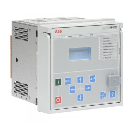
Section 2 1MRS758335 B REU611 overview REF611 Overcurrent Earth-fault Phase unbalance Thermal overload AR sequence in progress Disturb.rec.trigged Trip circuit failure Breaker failure GUID-E15422BF-B3E6-4D02-8D43-D912D5EF0360 V1 EN Figure 2: Example of the LHMI 2.4.1 Display The LHMI includes a graphical display that supports two character sizes. The character size depends on the selected language. -
Page 19: Leds
Section 2 1MRS758335 B REU611 overview GUID-24ADB995-439A-4563-AACE-1FAA193A8EF9 V1 EN Figure 3: Display layout 1 Header 2 Icon 3 Content 4 Scroll bar (displayed when needed) 2.4.2 LEDs The LHMI includes three protection indicators above the display: Ready, Start and Trip. There are also 8 programmable LEDs on front of the LHMI. -
Page 20: Web Hmi
Section 2 1MRS758335 B REU611 overview GUID-B681763E-EC56-4515-AC57-1FD5349715F7 V1 EN Figure 4: LHMI keypad with object control, navigation and command push buttons and RJ-45 communication port Web HMI The WHMI allows secure access to the protection relay via a Web browser. When the Secure Communication parameter in the protection relay is activated, the Web server is forced to take a secured (HTTPS) connection to WHMI using TLS encryption.The WHMI is verified with Internet Explorer 8.0, 9.0, 10.0 and 11.0. -
Page 21: Command Buttons
Section 2 1MRS758335 B REU611 overview GUID-CD531B61-6866-44E9-B0C1-925B48140F3F V2 EN Figure 5: Example view of the WHMI The WHMI can be accessed locally and remotely. • Locally by connecting the laptop to the protection relay via the front communication port. • Remotely over LAN/WAN. -
Page 22: Authorization
Section 2 1MRS758335 B REU611 overview Name Description Rejecting changes Showing context sensitive help messages Error icon Clearing events Triggering the disturbance recorder manually Saving values to TXT or CSV file format Freezing the values so that updates are not displayed Receiving continuous updates to the monitoring view Deleting the disturbance record Deleting all disturbance records... -
Page 23: Audit Trail
Section 2 1MRS758335 B REU611 overview Table 6: Predefined user categories Username User rights VIEWER Read only access OPERATOR • Selecting remote or local state with (only locally) • Changing setting groups • Controlling • Clearing indications ENGINEER • Changing settings •... - Page 24 Section 2 1MRS758335 B REU611 overview Table 7: Audit trail events Audit trail event Description Configuration change Configuration files changed Firmware change Firmware changed Firmware change fail Firmware change failed Attached to retrofit test case Unit has been attached to retrofit case Removed from retrofit test case Removed from retrofit test case Setting group remote...
-
Page 25: Communication
Section 2 1MRS758335 B REU611 overview Table 8: Comparison of authority logging levels Audit trail event Authority logging level Configurati Setting Setting Settings None on change group group, edit control Configuration change ● ● ● ● ● Firmware change ● ●... -
Page 26: Self-Healing Ethernet Ring
Section 2 1MRS758335 B REU611 overview where the highest performance class with a total transmission time of 3 ms is supported. The protection relay meets the GOOSE performance requirements for tripping applications in distribution substations, as defined by the IEC 61850 standard. -
Page 27: Ethernet Redundancy
Section 2 1MRS758335 B REU611 overview Client A Client B Network Network Manag ed Eth ernet switch Manag ed Eth ernet switch with RSTP su pport with RSTP su pport GUID-A19C6CFB-EEFD-4FB2-9671-E4C4137550A1 V2 EN Figure 6: Self-healing Ethernet ring solution The Ethernet ring solution supports the connection of up to 30 protection relays. - Page 28 Section 2 1MRS758335 B REU611 overview IEC 62439-3:2012 cancels and replaces the first edition published in 2010. These standard versions are also referred to as IEC 62439-3 Edition 1 and IEC 62439-3 Edition 2. The protection relay supports IEC 62439-3:2012 and it is not compatible with IEC 62439-3:2010. Each PRP node, called a doubly attached node with PRP (DAN), is attached to two independent LANs operated in parallel.
-
Page 29: Secure Communication
Section 2 1MRS758335 B REU611 overview • Via an external redundancy box (RedBox) or a switch capable of connecting to PRP and normal networks • By connecting the node directly to LAN A or LAN B as SAN • By connecting the node to the protection relay's interlink port HSR applies the PRP principle of parallel operation to a single ring, treating the two directions as two virtual LANs. -
Page 31: Section 3 Reu611 Standardized Configuration
Section 3 1MRS758335 B REU611 standardized configuration Section 3 REU611 standardized configuration Standardized configuration REU611 is available in one configuration. To increase the user-friendliness of the configuration and to emphasize the simplicity of usage of the relay, only the application-specific parameters need setting within the relay's intended area of application. -
Page 32: Switch Groups
Section 3 1MRS758335 B REU611 standardized configuration Function IEC 61850 Frequency measurement FMMXU Other Input switch group ISWGAPC Output switch group OSWGAPC Selector SELGAPC Minimum pulse timer (2 pcs) TPGAPC Move (8 pcs) MVGAPC 1, 2, ... = Number of included instances. The instances of a protection function represent the number of identical protection function blocks available in the standardized configuration. -
Page 33: Output Switch Group Oswgapc
Section 3 1MRS758335 B REU611 standardized configuration GUID-2D549B56-6CF7-4DCB-ACDE-E9EF601868A8 V1 EN Figure 9: Input switch group ISWGAPC 3.2.2 Output switch group OSWGAPC The output switch group OSWGAPC has a number of inputs and one output. Every input and output has a read-only description. OSWGAPC is used for connecting one or several inputs to the output of the switch group via OR logic. - Page 34 Section 3 1MRS758335 B REU611 standardized configuration GUID-E3AEC7AB-2978-402D-8A80-C5DE9FED67DF V1 EN Figure 11: Selector switch group SELGAPC REU611 Application Manual...
-
Page 35: Connection Diagrams
Section 3 1MRS758335 B REU611 standardized configuration Connection diagrams REU611 X130 X100 BI 1 BI 2 BI 3 BI 4 60 - 210V U12B 60 - 210V 60 - 210V 60 - 210V 60 - 210V TCS1 TCS2 GUID-45AA211F-CF77-4974-BBF6-4FC34B46EF3B V1 EN Figure 12: Connection diagram for configuration A (voltage protection with phase-to-phase voltage measurement) - Page 36 Section 3 1MRS758335 B REU611 standardized configuration REU611 X130 BI 1 BI 2 BI 3 BI 4 60 - 210V U12B 60 - 210V 60 - 210V 60 - 210V 60 - 210V GUID-90BD624C-28F1-4B93-8A2B-708E480A07A8 V1 EN Figure 13: Connection diagram for configuration A (voltage protection with phase-to-earth voltage measurement) REU611 Application Manual...
-
Page 37: Configuration A
Section 3 1MRS758335 B REU611 standardized configuration Configuration A 3.4.1 Applications Configuration A for voltage and frequency-based protection is mainly intended for utility and industrial power systems and distribution systems including networks with distributed power generation. The configuration handles fault conditions originating from abnormal voltages in the power system. -
Page 38: Functions
Section 3 1MRS758335 B REU611 standardized configuration 3.4.2 Functions REU611 VOLTAGE PROTECTION RELAY STANDARD CONFIGURATION PROTECTION LOCAL HMI ALSO AVAILABLE 2× - Disturbance and fault recorders Master Trip - Event log and recorded data Lockout relay - Local/Remote push button on LHMI 94/86 - Self-supervision Control... -
Page 39: Predefined Disturbance Recorder Connections
Section 3 1MRS758335 B REU611 standardized configuration Table 12: Default connections for binary outputs Binary input Description Connector pins X100-PO1 Close circuit breaker X100:6-7 X100-PO2 General start indication X100:8-9 X100-SO1 Overvoltage operate indication X100:10-12 X100-SO2 Undervoltage operate indication X100:13-14 X100-PO3 Open circuit breaker/trip coil 1 X100:15-19 X100-PO4... -
Page 40: Functional Diagrams For Protection
Section 3 1MRS758335 B REU611 standardized configuration The analog channels have fixed connections towards the different function blocks inside the protection relay’s configuration. Exceptions to this rule are the 12 analog channels available for the disturbance recorder function. These channels are freely selectable and a part of the disturbance recorder’s parameter settings. - Page 41 Section 3 1MRS758335 B REU611 standardized configuration UNDERVOLTAGE PROTECTION INDICATION PHPTUV1 3U<(1) 27(1) OPERATE BLOCK START PHPTUV2 3U<(2) 27(2) OSWGAPC8 OPERATE IN_4 BLOCK START IN_5 SELGAPC4 IN_9 OUT_2 LED 2 IN_6 PHPTUV3 3U<(3) 27(3) OPERATE BLOCK START GUID-0E0A1B18-45A8-4FDB-BCFB-9FFC175CD53B V1 EN Figure 16: Undervoltage protection Three undervoltage protection stages PHPTUV1...3 offer protection against...
- Page 42 Section 3 1MRS758335 B REU611 standardized configuration RESIDUAL OVERVOLTAGE PROTECTION ROVPTOV1 >(1) 59G(1) OPERATE BLOCK START OSWGAPC9 ROVPTOV2 >(2) IN_7 59G(2) SELGAPC4 IN_8 IN_10 OUT_3 LED 3 OPERATE BLOCK START IN_9 ROVPTOV3 >(3) 59G(3) OPERATE BLOCK START GUID-77BDA0D6-968E-4EF0-84E0-ED91580217A7 V1 EN Figure 17: Residual overvoltage protection The residual overvoltage protection ROVPTOV provides earth-fault protection by...
- Page 43 Section 3 1MRS758335 B REU611 standardized configuration POSITIVE AND NEGATIVE SEQUENCE PROTECTION INDICATION PSPTUV1 U1<(1) 47U+(1) OPERATE BLOCK START PSPTUV2 U1<(2) 47U+(2) OSWGAPC10 OPERATE IN_12 BLOCK START IN_13 SELGAPC4 IN_11 OUT_4 LED 4 IN_14 NSPTOV1 U2>(1) IN_15 47O-(1) OPERATE BLOCK START NSPTOV2 U2>(2)
- Page 44 Section 3 1MRS758335 B REU611 standardized configuration FREQUENCY PROTECTION INDICATION FRPFRQ1 f>/f<,df/dt (1) 81(1) OPERATE BLOCK START OSWGAPC16 SELGAPC4 IN_12 IN_17 OUT_5 LED 5 FRPFRQ2 f>/f<,df/dt (2) 81(2) OPERATE BLOCK START GUID-8E6B38BF-E8C6-4346-9EA4-F6A3DB231343 V1 EN Figure 19: Frequency protection The selectable underfrequency or overfrequency protection FRPFRQ prevents damage to network components under unwanted frequency conditions.
-
Page 45: Functional Diagrams For Disturbance Recorder And Trip Circuit Supervision
Section 3 1MRS758335 B REU611 standardized configuration 3.4.3.2 Functional diagrams for disturbance recorder and trip circuit supervision DISTURBANCE RECORDER RDRE1 PHPTOV1_START PHPTOV2_START PHPTOV3_START PHPTOV1_OPERATE PHPTUV1_START PHPTOV2_OPERATE PHPTUV2_START PHPTOV3_OPERATE PHPTUV3_START PSPTUV1_START PSPTUV2_START NSPTOV1_START PHPTUV1_OPERATE NSPTOV2_START PHPTUV2_OPERATE ROVPTOV1_START PHPTUV3_OPERATE ROVPTOV2_START ROVPTOV3_START OSWGAPC11 SELGAPC4 FRPFRQ1_START ROVPTOV1_OPERATE... - Page 46 Section 3 1MRS758335 B REU611 standardized configuration Channel number Channel ID text Level trigger mode Binary channel 13 ROVPTOV3_START 1=positive or rising Binary channel 14 FRPFRQ1_START 1=positive or rising Binary channel 15 FRPFRQ2_START 1=positive or rising Binary channel 16 PHPTOV_OPERATE 1=positive or rising Binary channel 17 PHPTUV_OPERATE...
-
Page 47: Functional Diagrams For Control
Section 3 1MRS758335 B REU611 standardized configuration 3.4.3.3 Functional diagrams for control MASTER TRIP #1 OSWGAPC1 IN_1 PHPTOV1_OPERATE IN_2 PHPTOV2_OPERATE IN_3 PHPTOV3_OPERATE IN_4 PHPTUV1_OPERATE IN_5 PHPTUV2_OPETATE IN_6 PHPTUV3_OPERATE IN_7 TRPPTRC1 ROVPTOV1_OPERATE SELGAPC3 IN_8 BLOCK TRIP ROVPTOV2_OPERATE IN_1 OUT_5 OPERATE CL_LKOUT X100 PO3 IN_9 ROVPTOV3_OPERTAE... - Page 48 Section 3 1MRS758335 B REU611 standardized configuration TRPPTRC1 and TRPPTRC2 provide the lockout/latching function, event generation and the trip signal duration setting. One binary input through SELGAPC1 can be connected to the RST_LKOUT input of the master trip. If the lockout operation mode is selected, it is used to enable external reset.
-
Page 49: Switch Groups
Section 3 1MRS758335 B REU611 standardized configuration COMMON ALARM INDICATION 1 & 2 OSWGAPC3 IN_1 PHPTOV1_START IN_2 PHPTOV2_START IN_3 PHPTOV3_START IN_4 PHPTUV1_START IN_5 PHPTUV2_START IN_6 PHPTUV3_START IN_7 TPGAPC1 ROVPTOV1_START OUT1 IN_8 ROVPTOV2_START IN_9 ROVPTOV3_START IN_10 FRPFRQ1_START IN_11 FRPFRQ2_START IN_12 NSPTOV1_START IN_13 NSPTOV2_START IN_14... -
Page 50: Binary Inputs
Section 3 1MRS758335 B REU611 standardized configuration Binary Inputs Protection and Control Binary Outputs and LEDs OSWGAPC2 ROVPTOV2 ROVPTOV1 SELGAPC4 SELGAPC1 OSWGAPC1 SELGAPC3 Binary Inputs Binary Outputs ROVPTOV3 PHPTUV1 (1..4) (1...6) ISWGAPC2 Master trip PHPTUV2 PHPTUV3 ISWGAPC1 OSWGAPC6 PHPTOV1 PHPTOV2 Blocking OSWGAPC5 PHPTOV3... - Page 51 Section 3 1MRS758335 B REU611 standardized configuration PHPTOV1_BLOCK PHPTOV2_BLOCK PHPTOV3_BLOCK PHPTUV1_BLOCK PHPTUV2_BLOCK PHPTUV3_BLOCK ROVPTOV1_BLOCK Blocking 1 ISWGAPC1 ROVPTOV2_BLOCK ROVPTOV3_BLOCK NSPTOV1_BLOCK NSPTOV2_BLOCK PSPTUV1_BLOCK X130-BI1 PSPTUV2_BLOCK FRPFRQ1_BLOCK FRPFRQ2_BLOCK X130-BI2 SELGAPC1 X130-BI3 PHPTOV1_BLOCK PHPTO V2_BLOCK X130-BI4 PHPTO V3_BLOCK PHPTUV1_BLOCK PHPTUV2_BLOCK PHPTUV3_BLOCK ROVPTOV1_BLOCK Blocking 2 ISWGAPC2 ROVPTOV2_BLOCK ROVPTOV3_BLOCK...
- Page 52 Section 3 1MRS758335 B REU611 standardized configuration SELGAPC1 X130/1-2 BI1 Blocking 1 X130-BI1 IN_1 OUT_1 ISWGAPC1_IN X130/3-4 BI2 CBXCBR1_POSCLOSE CB Closed Position X130-BI2 IN_2 OUT_2 SELGAPC2_IN_1 X130/5-6 BI3 X130-BI3 IN_3 OUT_3 CBXCBR1_POSOPEN CB Open Position SELGAPC2_IN_2 TRPPTRC1/2_RST X130/7-8 BI4 IN_4 X130-BI4 OUT_4 TRPTTRC1_RST_LKOUT...
- Page 53 Section 3 1MRS758335 B REU611 standardized configuration ISWGAPC1 OUT_1 PHPTOV1_BLOCK PHPTOV2_BLOCK OUT_2 PHPTOV3_BLOCK OUT_3 PHPTUV1_BLOCK OUT_4 PHPTUV2_BLOCK OUT_5 OUT_6 PHPTUV3_BLOCK OUT_7 ROVPTOV1_BLOCK OUT_8 ROVPTOV2_BLOCK Blocking 1 ROVPTOV3_BLOCK OUT_9 NSPTOV1_BLOCK OUT_10 OUT_11 NSPTOV2_BLOCK OUT_12 PSPTUV1_BLOCK PSPTUV2_BLOCK OUT_13 OUT_14 FRPFRQ1_BLOCK OUT_15 FRPFRQ2_BLOCK GUID-65F2F3B6-3D6D-4126-891E-9C7AD6122367 V1 EN Figure 28: ISWGAPC1...
-
Page 54: Internal Signal
Section 3 1MRS758335 B REU611 standardized configuration ISWGAPC2 OUT_1 PHPTOV1_BLOCK PHPTOV2_BLOCK OUT_2 PHPTOV3_BLOCK OUT_3 PHPTUV1_BLOCK OUT_4 PHPTUV2_BLOCK OUT_5 OUT_6 PHPTUV3_BLOCK ROVPTOV1_BLOCK OUT_7 ROVPTOV2_BLOCK OUT_8 Blocking 2 ROVPTOV3_BLOCK OUT_9 NSPTOV1_BLOCK OUT_10 NSPTOV2_BLOCK OUT_11 PSPTUV1_BLOCK OUT_12 PSPTUV2_BLOCK OUT_13 FRPFRQ1_BLOCK OUT_14 FRPFRQ2_BLOCK OUT_15 GUID-21043993-1044-4B8B-81E5-BF45A21D79CB V1 EN Figure 29: ISWGAPC2... -
Page 55: Binary Outputs And Leds
Section 3 1MRS758335 B REU611 standardized configuration SELGAPC2 CB Closed Position SELGAPC1_OUT_2 IN_1 OUT_1 TCSSCBR1_BLOCK CB Open Position SELGAPC1_OUT_3 IN_2 OUT_2 TCSSCBR2_BLOCK GUID-BC1E889E-D80E-4561-A70B-9986BFB374F7 V1 EN Figure 31: SELGAPC2 3.4.4.3 Binary outputs and LEDs In the standard configuration A, the signals are routed to binary outputs and LEDs are configured by OSWGAPCs. - Page 56 Section 3 1MRS758335 B REU611 standardized configuration PHPTOV1_OPERATE PHPTOV2_OPERATE PHPTOV3_OPERATE PHPTUV1_OPERATE PHPTUV2_OPERATE Master Trip 1 OSWGAPC1 TRPPTRC1 PHPTUV3_OPERATE ROVPTOV1_OPERATE ROVPTOV2_OPERATE ROVPTOV3_OPERATE FRPFRQ1_OPERATE Master Trip 2 OSWGAPC2 TRPPTRC2 FRPFRQ2_OPERATE NSPTOV1_OPERATE NSPTOV2_OPERATE PSPTUV1_OPERATE PSPTUV2_OPERATE TPGAPC1 PHPTOV1_START Start 1 OSWGAPC3 X100 PO1 OUT1 PHPTOV2_START PHPTOV3_START PHPTUV1_START...
- Page 57 Section 3 1MRS758335 B REU611 standardized configuration PHPTOV1_OPERATE PHPTOV2_OPERATE PHPTOV3_OPERATE PHPTUV1_OPERATE Master Trip 1 OSWGAPC1 TRPPTRC1 PHPTUV2_OPERATE PHPTUV3_OPERATE ROVPTOV1_OPERATE ROVPTOV2_OPERATE ROVPTOV3_OPERATE Master Trip 2 FRPFRQ1_OPERATE OSWGAPC2 TRPPTRC2 FRPFRQ2_OPERATE NSPTOV1_OPERATE NSPTOV2_OPERATE PSPTUV1_OPERATE PSPTUV2_OPERATE Start 1 OSWGAPC3 PHPTOV1_START PHPTOV2_START PHPTOV3_START PHPTUV1_START PHPTUV2_START Start 2 OSWGAPC4 PHPTUV3_START...
- Page 58 Section 3 1MRS758335 B REU611 standardized configuration SELGAPC3 CBXCBR_EXE_OP CB Open 1 IN_1 OUT_1 X100 PO1 TRPPTRC1_TRIP CB Open 2 IN_2 OUT_2 X100 PO2 CB Close IN_3 OUT_3 X100 SO1 Start 1 OUT1 IN_4 OUT_4 X100 SO2 TPGAPC1 Start 2 OUT2 IN_5 OUT_5...
- Page 59 Section 3 1MRS758335 B REU611 standardized configuration SELGAPC4 CBXCBR_EXE_OP CB O pen 1 IN_1 TRPPTRC1_TRIP CB O pen 2 IN_2 CB Close IN_3 Start 1 IN_4 Start 2 IN_5 Start 3 IN_6 LED1 OUT_1 Start 4 LED2 IN_7 OUT_2 Trip 1 IN_8 LED3 OUT_3...
- Page 60 Section 3 1MRS758335 B REU611 standardized configuration OSWGAPC1 IN_1 PHPTOV1_OPERATE IN_2 PHPTOV2_OPERATE IN_3 PHPTOV3_OPERATE IN_4 PHPTUV1_OPERATE IN_5 PHPTUV2_OPERATE PHPTUV3_OPERATE IN_6 IN_7 ROVPTOV1_OPERATE IN_8 ROVPTOV2_OPERATE Master trip 1 TRPPTRC 1_OPERATE IN_9 ROVPTOV3_OPERATE IN_10 FRPFRQ1_OPERATE IN_11 FRPFRQ2_OPERATE IN_12 NSPTOV1_OPERATE NSPTOV2_OPERATE IN_13 PSPTUV1_OPERATE IN_14 PSPTUV2_OPERATE IN_15...
- Page 61 Section 3 1MRS758335 B REU611 standardized configuration OSWGAPC2 IN_1 PHPTOV1_OPERATE IN_2 PHPTOV2_OPERATE IN_3 PHPTOV3_OPERATE IN_4 PHPTUV1_OPERATE IN_5 PHPTUV2_OPERATE PHPTUV3_OPERATE IN_6 IN_7 ROVPTOV1_OPERATE IN_8 ROVPTOV2_OPERATE Master trip 2 TRPPTRC 2_OPERATE IN_9 ROVPTOV3_OPERATE IN_10 FRPFRQ1_OPERATE IN_11 FRPFRQ2_OPERATE IN_12 NSPTOV1_OPERATE NSPTOV2_OPERATE IN_13 PSPTUV1_OPERATE IN_14 PSPTUV2_OPERATE IN_15...
- Page 62 Section 3 1MRS758335 B REU611 standardized configuration OSWGAPC3 IN_1 PHPTOV1_START IN_2 PHPTOV2_START IN_3 PHPTOV3_START IN_4 PHPTUV1_START IN_5 PHPTUV2_START PHPTUV3_START IN_6 IN_7 ROVPTOV1_START IN_8 ROVPTOV2_START Start 1 TPGAPC1_IN1 SELGAPC4_IN_4 IN_9 ROVPTOV3_START IN_10 FRPFRQ1_START IN_11 FRPFRQ2_START IN_12 NSPTOV1_START NSPTOV2_START IN_13 PSPTUV1_START IN_14 PSPTUV2_START IN_15 GUID-1CEEF190-B5CB-40C0-8D3B-B85233DB3BDF V1 EN...
- Page 63 Section 3 1MRS758335 B REU611 standardized configuration OSWGAPC4 PHPTOV1_START IN_1 IN_2 PHPTOV2_START IN_3 PHPTOV3_START IN_4 PHPTUV1_START IN_5 PHPTUV2_START PHPTUV3_START IN_6 IN_7 ROVPTOV1_START Start 2 TPGAPC1_IN2 SELGAPC4_IN_5 IN_8 ROVPTOV2_START IN_9 ROVPTOV3_START IN_10 FRPFRQ1_START IN_11 FRPFRQ2_START NSPTO V1_START IN_12 NSPTO V2_START IN_13 PSPTUV1_START IN_14 PSPTUV2_START...
- Page 64 Section 3 1MRS758335 B REU611 standardized configuration OSWGAPC5 PHPTOV1_START IN_1 IN_2 PHPTOV2_START IN_3 PHPTOV3_START IN_4 PHPTUV1_START IN_5 PHPTUV2_START PHPTUV3_START IN_6 IN_7 ROVPTOV1_START Start 3 TPGAPC2_IN1 IN_8 ROVPTOV2_START SELGAPC4_IN_6 IN_9 ROVPTOV3_START IN_10 FRPFRQ1_START IN_11 FRPFRQ2_START NSPTO V1_START IN_12 NSPTO V2_START IN_13 PSPTUV1_START IN_14 PSPTUV2_START...
- Page 65 Section 3 1MRS758335 B REU611 standardized configuration OSWGAPC6 PHPTOV1_START IN_1 IN_2 PHPTOV2_START PHPTOV3_START IN_3 IN_4 PHPTUV1_START IN_5 PHPTUV2_START PHPTUV3_START IN_6 IN_7 ROVPTOV1_START TPGAPC2_IN2 ROVPTOV2_START IN_8 Start 4 SELGAPC4_IN_7 ROVPTOV3_START IN_9 FRPFRQ1_START IN_10 FRPFRQ2_START IN_11 IN_12 NSPTOV1_START IN_13 NSPTOV2_START PSPTUV1_START IN_14 PSPTUV2_START IN_15 GUID-21366E41-D912-47F4-8E79-0A1897838DE8 V1 EN...
- Page 66 Section 3 1MRS758335 B REU611 standardized configuration OSWGAPC7 IN_1 PHPTOV1_OPERATE IN_2 PHPTOV2_OPERATE IN_3 PHPTOV3_OPERATE IN_4 PHPTUV1_OPERATE IN_5 PHPTUV2_OPERATE PHPTUV3_OPERATE IN_6 IN_7 ROVPTOV1_OPERATE IN_8 ROVPTOV2_OPERATE Trip 1 TPGAPC3_IN1 SELGAPC4_IN_8 IN_9 ROVPTOV3_OPERATE IN_10 FRPFRQ1_OPERATE IN_11 FRPFRQ2_OPERATE IN_12 PSPTUV1_OPERATE PSPTUV2_OPERATE IN_13 NSPTOV1_OPERATE IN_14 NSPTOV2_OPERATE IN_15 GUID-4C59046E-A106-47B2-9278-872145522C9A V1 EN...
- Page 67 Section 3 1MRS758335 B REU611 standardized configuration OSWGAPC8 IN_1 PHPTOV1_OPERATE IN_2 PHPTOV2_OPERATE IN_3 PHPTOV3_OPERATE IN_4 PHPTUV1_OPERATE IN_5 PHPTUV2_OPERATE PHPTUV3_OPERATE IN_6 IN_7 ROVPTOV1_OPERATE IN_8 ROVPTOV2_OPERATE Trip 2 TPGAPC3_IN2 SELGAPC4_IN_9 IN_9 ROVPTOV3_OPERATE IN_10 FRPFRQ1_OPERATE IN_11 FRPFRQ2_OPERATE IN_12 PSPTUV1_OPERATE PSPTUV2_OPERATE IN_13 NSPTOV1_OPERATE IN_14 NSPTOV2_OPERATE IN_15 GUID-89D0D99C-9A90-4F63-9E25-251108BFA4B3 V1 EN...
- Page 68 Section 3 1MRS758335 B REU611 standardized configuration OSWGAPC9 IN_1 PHPTOV1_OPERATE IN_2 PHPTOV2_OPERATE IN_3 PHPTOV3_OPERATE IN_4 PHPTUV1_OPERATE IN_5 PHPTUV2_OPERATE PHPTUV3_OPERATE IN_6 IN_7 ROVPTOV1_OPERATE IN_8 ROVPTOV2_OPERATE TPGAPC4_IN1 Trip 3 SELGAPC4_IN_10 IN_9 ROVPTOV3_OPERATE IN_10 FRPFRQ1_OPERATE IN_11 FRPFRQ2_OPERATE IN_12 PSPTUV1_OPERATE PSPTUV2_OPERATE IN_13 NSPTOV1_OPERATE IN_14 NSPTOV2_OPERATE IN_15 GUID-689B84B6-25A0-4CB7-A374-ED2E73A41A91 V1 EN...
- Page 69 Section 3 1MRS758335 B REU611 standardized configuration OSWGAPC10 IN_1 PHPTOV1_OPERATE IN_2 PHPTOV2_OPERATE IN_3 PHPTOV3_OPERATE IN_4 PHPTUV1_OPERATE IN_5 PHPTUV2_OPERATE PHPTUV3_OPERATE IN_6 IN_7 ROVPTOV1_OPERATE IN_8 ROVPTOV2_OPERATE TPGAPC4_IN2 Trip 4 SELGAPC4_IN_11 IN_9 ROVPTOV3_OPERATE IN_10 FRPFRQ1_OPERATE IN_11 FRPFRQ2_OPERATE IN_12 PSPTUV1_OPERATE PSPTUV2_OPERATE IN_13 NSPTOV1_OPERATE IN_14 NSPTOV2_OPERATE IN_15 GUID-BA32398F-8C21-4566-9C0F-A7874307413C V1 EN...
- Page 70 Section 3 1MRS758335 B REU611 standardized configuration OSWGAPC11 RDRE_TRIGGERED IN_1 TCSSCBR1_ALARM IN_2 TCSSCBR2_ALARM IN_3 External Trip IN_4 SELGAPC1_OUT_6 IN_5 TRPPTRC1_CL_LKOUT Alarm 1 TRPPTRC2_CL_LKOUT IN_6 TPGAPC5_IN1 SELGAPC4_IN_12 IN_7 BUS_VT_MCB_OPEN OVERVOLTAGE_OPERATE IN_8 IN_9 UNDERVOLTAGE_OPERATE IN_10 IN_11 IN_12 GUID-53D8F638-3D65-4A83-BD3A-CCCF5C4F9CFC V1 EN Figure 46: OSWGAPC11 OSWGAPC12 RDRE_TRIGGERED...
- Page 71 Section 3 1MRS758335 B REU611 standardized configuration OSWGAPC13 RDRE_TRIGGERED IN_1 TCSSCBR1_ALARM IN_2 TCSSCBR2_ALARM IN_3 Ext ernal Trip IN_4 SELGAPC1_OUT_6 IN_5 TRPPTRC1_CL_LKOUT TRPPTRC2_CL_LKOUT IN_6 TPGAPC6_IN1 Alarm 3 SELGAPC4_IN_14 IN_7 BUS_VT_MCB_OPEN OVERVOLTAGE_OPERATE IN_8 IN_9 UNDERVOLTAGE_OPERATE IN_10 IN_11 IN_12 GUID-150A454F-3B7B-4CE0-8295-B7F038A2D45B V1 EN Figure 48: OSWGAPC13 OSWGAPC14 RDRE_TRIGGERED...
- Page 72 Section 3 1MRS758335 B REU611 standardized configuration OSWGAPC15 RDRE_TRIGGERED IN_1 TCSSCBR1_ALARM IN_2 TCSSCBR2_ALARM IN_3 Ext ernal Trip IN_4 SELGAPC1_OUT_6 IN_5 TRPPTRC1_CL_LKOUT TRPPTRC2_CL_LKOUT IN_6 TPGAPC7_IN1 Alarm 5 SELGAPC4_IN_16 IN_7 BUS_VT_MCB_OPEN OVERVOLTAGE_OPERATE IN_8 IN_9 UNDERVOLTAGE_OPERATE IN_10 IN_11 IN_12 GUID-945CCB97-C5D5-419E-8A17-E70CF2D1AB2D V1 EN Figure 50: OSWGAPC15 OSWGAPC16 RDRE_TRIGGERED...
-
Page 73: Goose
Section 3 1MRS758335 B REU611 standardized configuration 3.4.4.4 GOOSE There are 20 GOOSERCV_BIN functions in the configuration. Each GOOSERVC_BIN function can be connected to one received binary GOOSE signal. The signal connection can be configured in PCM600. • GOOSERCV_BIN instances 0 and 1 are used for blocking protection functions. Signals from these two GOOSERCV_BINs are connected to ISWGAPC9. - Page 74 Section 3 1MRS758335 B REU611 standardized configuration GOOSERCV_BIN:0 and GOOSERCV_BIN:1. The outputs are connected to block inputs of the protection functions. ISWGAPC9 OUT_1 PHPTOV1_BLOCK PHPTOV2_BLOCK OUT_2 PHPTOV3_BLOCK OUT_3 OUT_4 PHPTUV1_BLOCK OUT_5 PHPTUV2_BLOCK OUT_6 PHPTUV3_BLOCK ROVPTOV1_BLOCK OUT_7 ROVPTOV2_BLOCK OUT_8 GOOSE Blocking OUT_9 ROVPTOV3_BLOCK OUT_10...
-
Page 75: Section 4 Protection Relay's Physical Connections
Section 4 1MRS758335 B Protection relay's physical connections Section 4 Protection relay's physical connections Inputs 4.1.1 Energizing inputs 4.1.1.1 Phase voltage Table 16: Phase voltage inputs Terminal Description X130:11-12 X130:13-14 X130:15-16 Table 17: Reference voltage measurement Terminal Description X130:9-10 U12B 4.1.1.2 Residual voltage Table 18:... -
Page 76: Binary Inputs
Section 4 1MRS758335 B Protection relay's physical connections 4.1.3 Binary inputs The binary inputs can be used, for example, to generate a blocking signal, to unlatch output contacts, to trigger the disturbance recorder or for remote control of protection relay settings. Binary inputs of slot X130 are available with AIM0006 module. -
Page 77: Outputs For Signalling
Section 4 1MRS758335 B Protection relay's physical connections 4.2.2 Outputs for signalling Output contacts SO1 and SO2 in slot X100 can be used for signalling on start and tripping of the protection relay. On delivery from the factory, the start and alarm signals from all the protection stages are routed to signalling outputs. -
Page 79: Section 5 Glossary
Section 5 1MRS758335 B Glossary Section 5 Glossary 611 series Series of numerical protection and control relays for low-end protection and supervision applications of utility substations, and industrial switchgear and equipment Circuit breaker Comma-separated values Doubly attached node 1. Direct current 2. - Page 80 Section 5 1MRS758335 B Glossary IRIG-B Inter-Range Instrumentation Group's time code format B Local area network Connector type for glass fiber cable, IEC 61754-20 Liquid crystal display Light-emitting diode LHMI Local human-machine interface Media access control Miniature circuit breaker 1. Manufacturing message specification 2.
- Page 84 Contact us ABB Oy Medium Voltage Products, Distribution Automation P.O. Box 699 FI-65101 VAASA, Finland Phone +358 10 22 11 +358 10 22 41599 www.abb.com/mediumvoltage www.abb.com/substationautomation...