ABB Relion 620 Series Applications Manual
Advanced recloser protection and control
Hide thumbs
Also See for Relion 620 Series:
- Technical manual (1224 pages) ,
- Operation manual (152 pages) ,
- Protocol manual (88 pages)

Related Manuals for ABB Relion 620 Series


Summary of Contents for ABB Relion 620 Series
- Page 1 ® Relion 620 series Advanced Recloser Protection and Control RER620 Application Manual...
- Page 3 Document ID: 1MAC308145-MB Issued: 7/20/2017 Revision: E Product version: 1.3 © Copyright 2017 ABB. All rights reserved.
- Page 4 Copyright This document and parts thereof must not be reproduced or copied without written permission from ABB, and the contents thereof must not be imparted to a third party, nor used for any unauthorized purpose. The software or hardware described in this document is furnished under a license and may be used, copied, or disclosed only in accordance with the terms of such license.
- Page 5 This document has been carefully checked by ABB but deviations cannot be completely ruled out. In case any errors are detected, the reader is kindly requested to notify the manufacturer.
- Page 6 (Low-voltage directive 2006/95/EC). This conformity is the result of tests conducted by ABB in accordance with the product standards EN 50263 and EN 60255-26 for the EMC directive, and with the product standards EN 60255-6 and EN 60255-27 for the low voltage directive.
-
Page 7: Table Of Contents
Section 1MAC308145-MB E Table of Contents Section 1 Introduction................3 This manual....................3 Intended audience..................3 Product documentation ................4 Product documentation set ..............4 Document revision history..............5 Related documentation ............... 5 Symbols and conventions ................ 5 Safety indication symbols..............5 Manual conventions ................ - Page 8 Section 1MAC308145-MB E OPUP Mode - Only Picked Up Phases ........58 OOAP Mode - One Or All Phases..........58 APAT: (All Poles All the Time) ............. 59 Autorecloser logic................59 Input function blocks (SDAIGGIOs)........... 60 Auto Recloser Block (SDARREC) ............. 62 Output Interface Block (SDAOGGIO)..........
-
Page 9: Introduction
Section 1 1MAC308145-MB E Introduction Section 1 Introduction This manual The application manual contains application descriptions and setting guidelines sorted per function. The manual can be used to find out when and for what purpose a typical protection function can be used. The manual can also be used when calculating settings. Intended audience This manual addresses the protection and control engineer responsible for planning, pre-engineering and engineering. -
Page 10: Product Documentation
Section 1 1MAC308145-MB E Introduction Product documentation 1.3.1 Product documentation set Application manual Engineering manual Installation manual Operation manual Technical manual Communication Protocol manual Protocol Points List manual Figure 1: The intended use of manuals in different lifecycles The engineering manual contains instructions on how to engineer the relays using the different tools in PCM600. -
Page 11: Document Revision History
C/08/14/2014 Content updated to correspond to the product series version D/09/30/2015 Content updated E/07/20/2017 Content updated Download the latest documents from the ABB web site http://www.abb.com/substationautomation. 1.3.3 Related documentation Name of the document Document ID Modbus Communication Protocol Manual 1MAC052634-MB... -
Page 12: Manual Conventions
Section 1 1MAC308145-MB E Introduction The caution icon indicates important information or warning related to the concept discussed in the text. It might indicate the presence of a hazard which could result in corruption of software or damage to equipment or property. -
Page 13: Functions, Codes And Symbols
Section 1 1MAC308145-MB E Introduction Function block 51P-1/2 Trip SPHLPTOC1(51P;3 Trip_A BLOCK TRIP Trip_B ENA_MULT PICKUP TRIP_A Trip_C TRIP_B Block TRIP_C PICKUP PICKUP_A ENA_MULT PICKUP_A PICKUP_B PICKUP_C PICKUP_B PICKUP_C Figure 2: Function block as it appears in the manual (left) and in the ACT (right) 1.4.3 Functions, codes and symbols All available functions are listed in the table. - Page 14 Section 1 1MAC308145-MB E Introduction Function IEC61850 IEC60617 ANSI/C37.2 Cold load timer 2 Phase A (in minutes) TPMGAPC1 TPM(1) 62CLD-2 Cold load timer 1 Phase B (in seconds) TPSGAPC2 TPS(2) 62CLD-3 Cold load timer 2 Phase B (in minutes) TPMGAPC2 TPM(2) 62CLD-4 Cold load timer 1 Phase C (in seconds)
- Page 15 Section 1 1MAC308145-MB E Introduction Function IEC61850 IEC60617 ANSI/C37.2 Ground current RESCMMXU1 Three-phase voltage, Source 1 VMMXU1 VA,VB,VC Three-phase voltage, Source 2 VMMXU2 3U(B) VA,VB,VC(2) Sequence voltages, Source 1 VSMSQI1 U1,U2,U0 V1,V2,V0 Sequence voltages, Source 2 VSMSQI2 U1,U2,U0(B) V1,V2,V0(2) Single and Three-phase power, Power factor and three phase energy, Source 1 APEMMXU1 P,SP,E P,SP,E...
- Page 16 Section 1 1MAC308145-MB E Introduction RER620 Application Manual...
-
Page 17: Rer620 Overview
RER620 is a member of ® ABB's Relion product family and part of its 620 protection and control product series. The 620 series relays are characterized by their compactness and withdrawable design. -
Page 18: Physical Hardware
• Relay User Management • Relay Users • Application Configuration • IED Compare Download connectivity packages from the ABB web site http://www.abb.com/substationautomation Physical hardware The relay consists of two main parts: plug-in unit and case. The plug-in unit content depends on the ordered functionality. - Page 19 Section 2 1MAC308145-MB E RER620 overview The optional BIO module can be added in the relay to all standard configurations. The connection diagrams of different hardware modules are presented in this manual. See the installation manual for more information about the case and the plug-in unit.
-
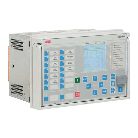
Page 20: Local Hmi
Section 2 1MAC308145-MB E RER620 overview Table 3: Number of physical connections in standard configuration Conf. Analog channels Binary channels VT/CVD RA01 and RA02 RA01 and RA02 with 1 BIO RA01 and RA02 with 2 BIO Local HMI Figure 3: LHMI The LHMI of the relay contains the following elements: •... -
Page 21: Lcd
Section 2 1MAC308145-MB E RER620 overview 2.3.1 The LHMI includes a graphical LCD that supports two character sizes. The character size depends on the selected language. Table 4: Characters and rows on the view Character size Rows in view Characters on row Large, variable width (13x14 4 rows min 8... -
Page 22: Web Hmi
Section 2 1MAC308145-MB E RER620 overview used to acknowledge alarms, reset indications, provide help and switch between local and remote control mode. Figure 5: LHMI keypad with object control, navigation and command push-buttons and RJ-45 communication port Web HMI The WHMI enables the user to access the relay via a web browser. The supported web browser versions are Internet Explorer 9.0, 10.0 and 11.0. -
Page 23: Authorization
Section 2 1MAC308145-MB E RER620 overview Figure 6: Example view of the WHMI The WHMI can be accessed locally and remotely. • Locally by connecting your laptop to the relay via the front communication port. • Remotely over LAN/WAN. Authorization The user categories have been predefined for the LHMI and the WHMI, each with different rights and default passwords. -
Page 24: Communication
Section 2 1MAC308145-MB E RER620 overview The default passwords can be changed with Administrator user rights. User authorization is disabled by default but WHMI always uses authorization. Table 5: Predefined user categories Username User rights VIEWER Read only access OPERATOR •... - Page 25 Section 2 1MAC308145-MB E RER620 overview All communication connectors, except for the front port connector, are placed on integrated communication modules. The relay can be connected to Ethernet-based communication systems via the RJ-45 connector (100BASE-TX) or the fiber-optic LC connector (100BASE-FX). Also, a serial interface is available for RS-232/RS-485 communication.
- Page 26 Section 2 1MAC308145-MB E RER620 overview RER620 Application Manual...
-
Page 27: Rer620 Application
RER620 as delivered from the factory. Table 6: Standard configurations Description Functional application Relay configuration configuration Single and Dual Source (6 VT inputs) - ABB RA01 Single and Dual Source (6 VT inputs) - G&W / other RA02 RER620 Application Manual... -
Page 28: Functions
Section 3 1MAC308145-MB E RER620 application Functions Table 7: Functions included in the RER620 standard configuration RA01, RA02 Function IEC61850 IEC60617 ANSI/C37.2 Current Protection Single-phase non-directional time overcurrent protection with 1-ph trip option, low stage SPHLPTOC1 3I>(1) Single-phase non-directional time overcurrent protection with 1-ph trip option, high stage 1 SPHLPTOC2 3I>(2) 50P-1... - Page 29 Section 3 1MAC308145-MB E RER620 application Function IEC61850 IEC60617 ANSI/C37.2 Zero sequence overvoltage protection, source1 ROVPTOV1 Uo>(1) 59N-1 Zero sequence overvoltage protection, source 2 ROVPTOV2 Uo>(2) 59N-2 Frequency Protection Underfrequency, Overfrequency, Frequency rate of change, Source 1, Stage 1 FRPFRQ1 f</f>,df/dt(1) 81-1 Underfrequency, Overfrequency, Frequency rate of change, Source 1, Stage 2...
-
Page 30: Default Led Connections
Section 3 1MAC308145-MB E RER620 application Function IEC61850 IEC60617 ANSI/C37.2 Move function block (8 outputs) MVGAPC1 MVGAPC1 MVGAPC1 Move function block (8 outputs) MVGAPC2 MVGAPC2 MVGAPC2 Pulse timer (8 timers) PTGAPC1 PTGAPC1 PTGAPC1 Pulse timer (8 timers) PTGAPC2 PTGAPC2 PTGAPC2 Generic control points (16 outputs) SPCGGIO1 SPCGGIO1... -
Page 31: One Touch Functions
Section 3 1MAC308145-MB E RER620 application Table 8: LED label assignments Label LED 1 Phase A LED 2 Phase B LED 3 Phase C LED 4 Ground LED 5 Current LED 6 Voltage LED 7 Time LED 8 Instantaneous LED 9 79 Lockout LED 10 Breaker Failure... - Page 32 Section 3 1MAC308145-MB E RER620 application Table 10: Programmable buttons and functional selection 9…16 (right column in the relay Programmable buttons area) Programmable Button Functional Selection Toggle Button 9 Ground Blocked (On/Off) Toggle Button 10 Re-close Blocked (On/Off) Toggle Button 11 Battery Test Toggle Button 12 50SEF (Blocked)
-
Page 33: Connection Diagrams
Section 3 1MAC308145-MB E RER620 application 3.2.3 Connection Diagrams Figure 7: RER620 Connection diagram for standard modules RER620 Application Manual... - Page 34 Section 3 1MAC308145-MB E RER620 application RER620 X105 X110 BI 1 BI 2 BI 3 BI 4 BI 5 BI 6 X10⁵ BI 7 BI 8 X110 BI 1 BI 2 BI 3 BI 4 BI 5 BI 6 BI 7 BI 8 1) Order Selectable - Optional Figure 8:...
-
Page 35: Functional Diagrams
Section 3 1MAC308145-MB E RER620 application Functional diagrams The functional diagrams describe the default input, output, alarm LED and function to function connections. The default connections can be viewed with ACT and changed according to the application requirements, if necessary. The analog channels, measurements from CTs and CVTs/ PTs, have fixed connections to the different function blocks inside the relay’s default configuration. - Page 36 Section 3 1MAC308145-MB E RER620 application Figure 9: Programmable button default mapping RER620 Application Manual...
-
Page 37: Functional Diagrams For Protection
Section 3 1MAC308145-MB E RER620 application SRGAPC1_R1 SPCGGIO1_O2 SPCGGIO1_O3 SRGAPC1_R2 SPCGGIO1_O1 SPCGGIO1_O2 SPCGGIO1_O3 SPCGGIO1_O4 SPCGGIO1_O5 SPCGGIO1_O6 SPCGGIO1_O4 SRGAPC1_R3 SPCGGIO1_O5 SRGAPC1_R4 SPCGGIO1_O6 SRGAPC1_R5 Figure 10: Programmable button mapping for remote blocking 3.3.1 Functional diagrams for protection The following functional diagrams describe the relay’s protection functionality in detail and according to the factory set default connections in ACT. - Page 38 Section 3 1MAC308145-MB E RER620 application Figure 11: Phase time overcurrent protection RER620 Application Manual...
- Page 39 Section 3 1MAC308145-MB E RER620 application SPCGGIO1_O7_SWITCH_MODE SPHIPTOC1_50P-3_OPERATE SPHIPTOC1(50P-3 BLOCK TRIP ENA_MULT PICKUP TRIP_A TRIP_B TRIP_C PICKUP_A PICKUP_B SPHIPTOC1_50P-3_OPERATE_A PICKUP_C SPHIPTOC1_50P-3_OPERATE_B SPHIPTOC1_50P-3_OPERATE_C SPHIPTOC1_50P-3_START_A SPHIPTOC1_50P-3_START_B SPHIPTOC1_50P-3_START_C Figure 12: Instantaneous phase overcurrent protection The ground-fault function 51N/50N is used as non-directional ground-fault protection for feeders.
- Page 40 Section 3 1MAC308145-MB E RER620 application Figure 13: Neutral and negative sequence protection blocking RER620 Application Manual...
- Page 41 Section 3 1MAC308145-MB E RER620 application Figure 14: Unbalance mode protection RER620 Application Manual...
- Page 42 Section 3 1MAC308145-MB E RER620 application Figure 15: Ground overcurrent protection RER620 Application Manual...
- Page 43 Section 3 1MAC308145-MB E RER620 application Figure 16: Sensitive earth fault protection RER620 Application Manual...
- Page 44 Section 3 1MAC308145-MB E RER620 application Figure 17: Cold Load Timers RER620 Application Manual...
- Page 45 Section 3 1MAC308145-MB E RER620 application The RER620 relay provides cold load timers in minutes or seconds resolution for various application needs. In total, six Cold load timers are available to provide utmost flexibility in cold-load inrush detection. The timer function blocks can be used for single phase or three phase blocking.
- Page 46 Section 3 1MAC308145-MB E RER620 application SPHLPTOC1_51P_OPERATE XEFLPTOC2_51N_OPERATE SDPHLPDOC1_67/51P-1_OPERATE SDPHLPDOC1_67/51P-2_OPERATE XDEFLPDEF1_67/51N-1_OPERATE XDEFLPDEF1_67/51N-2_OPERATE LED7_TIME_OPERATE EFLPTOC3_50SEF_OPERATE XNSPTOC1_46-1_OPERATE XNSPTOC2_46-2_OPERATE PDNSPTOC_46PD_OPERATE Figure 20: Time overcurrent protection LED indication PSPTOV1(59PS-1; BLOCK TRIP PSPTOV1_59PS-1_OPERATE PICKUP PSPTOV2(59PS-2; NSPTOV1(47-1;U2 BLOCK TRIP PSPTOV2_59PS-2_OPERATE PICKUP BLOCK TRIP NSPTOV1_47-1_OPERATE PICKUP NSPTOV2(47-2;U2 SPHPTOV1(59-1;3 BLOCK TRIP...
- Page 47 Section 3 1MAC308145-MB E RER620 application PSPTOV2_59PS-2_OPERATE PSPTOV1_59PS-1_OPERATE NSPTOV1_47-1_OPERATE SPHPTOV1_59-1_OPERATE NSPTOV2_47-2_OPERATE SPHPTOV2_59-2_OPERATE LED6_VOLTAGE_OPERATE SPHPTOV3_59-3_OPERATE SPHPTUV1_27-1_OPERATE SPHPTUV2_27-2_OPERATE SPHPTUV3_27-3_OPERATE ROVPTOV1_59N-1_OPERATE ROVPTOV2_59N-2_OPERATE Figure 22: Voltage protection LED indication FRPFRQ2(81-2;f> FRPFRQ1(81-1;f> BLOCK TRIP BLOCK TRIP FRPFRQ2_81-2_OPERATE FRPFRQ1_81-1_OPERATE OPR_OFRQ OPR_OFRQ OPR_UFRQ OPR_UFRQ OPR_FRG OPR_FRG PICKUP PICKUP ST_OFRQ ST_OFRQ...
- Page 48 Section 3 1MAC308145-MB E RER620 application Figure 25: Breaker (trip) failure protection RER620 Application Manual...
- Page 49 Section 3 1MAC308145-MB E RER620 application Figure 26: Breaker close failure protection RER620 Application Manual...
-
Page 50: Functional Diagrams For Control And Autoreclosing
Section 3 1MAC308145-MB E RER620 application 3.3.2 Functional diagrams for control and autoreclosing The loop control module (LCM) enables the RER620 to perform automatic loop restoration functions, commonly accepted as a means to significantly improve circuit reliability and to provide more effective system operation. The LCM is designed to implement a loop control scheme by providing switching operations of the recloser to sectionalize or remove the faulted section from the distribution system. - Page 51 Section 3 1MAC308145-MB E RER620 application Figure 27: Breaker control for RA01 RER620 Application Manual...
- Page 52 Section 3 1MAC308145-MB E RER620 application Figure 28: Breaker control for RA02 RER620 Application Manual...
- Page 53 Section 3 1MAC308145-MB E RER620 application Figure 29: Synch-check function RER620 “Latched Open” logic scheme: The RER620 has a user settable “Latched Open” logic scheme as a part of default configuration. This logic scheme will use one local HMI push button which will immediately open all breaker poles (see Figure 9 and Figure 27) and set the RER620 Application Manual...
- Page 54 Section 3 1MAC308145-MB E RER620 application ‘Latched_Open’ channel (see Figure 9). LHMI close, Remote/SCADA Close and Reclosing (79) re-close commands are not allowed while in the Latched Open state. “Latched Open” can be activated through push button 16 [Key 16], circled in the figure below, which is labeled as “Emergency Open 3 Ph”.
- Page 55 Section 3 1MAC308145-MB E RER620 application Figure 32: Auto reclose output function (Also refer to figure for Breaker Control) RER620 Application Manual...
- Page 56 Section 3 1MAC308145-MB E RER620 application PH_ORD_IN X115_UPD_Input1 PH_ORD_OUT_X115_OP_IN1_A X115_UPD_Input2 PH_ORD_OUT_X115_OP_IN2_B X115_UPD_Input3 PH_ORD_OUT_X115_OP_IN3_C PH_ORD_IN X115_UPD_IN1_CL_PH_A PH_ORD_OUT_X115_CL_IN1_A X115_UPD_IN2_CL_PH_B PH_ORD_OUT_X115_CL_IN2_B X115_UPD_IN3_CL_PH_C PH_ORD_OUT_X115_CL_IN3_C SPSCBR1(52CM;CB BLOCK TRV_T_OP_ALM POSOPEN_A TRV_T_CL_ALM PH_ORD_OUT_X115_OP_IN1_A POSOPEN_B SPR_CHR_ALM PH_ORD_OUT_X115_OP_IN2_B POSOPEN_C OPR_ALM PH_ORD_OUT_X115_OP_IN3_C POSCLOSE_A OPR_LO PH_ORD_OUT_X115_CL_IN1_A POSCLOSE_B IPOW_ALM PH_ORD_OUT_X115_CL_IN2_B POSCLOSE_C IPOW_LO PH_ORD_OUT_X115_CL_IN3_C PRES_ALM_IN CB_LIFE_ALM...
- Page 57 Section 3 1MAC308145-MB E RER620 application UDFCNT1(UDFCNT1 UP_CNT UPCNT_STS SPHLPTOC1_51P_OPERATE_A DOWN_CNT DNCNT_STS SPHLPTOC2_50P-1_OPERATE_A RESET SPHHPTOC1_50P-2_OPERATE_A SPCGGIO2_Reset_Trip_Counters LOAD SPHIPTOC1_50P-3_OPERATE_A SDPHLPDOC1_67/51P-1_OPERATE_A SDPHLPDOC1_67/51P-2_OPERATE_A UDFCNT2(UDFCNT2 UP_CNT UPCNT_STS DOWN_CNT DNCNT_STS SPCGGIO2_Reset_Trip_Counters RESET LOAD SPHLPTOC1_51P_OPERATE_B SPHLPTOC2_50P-1_OPERATE_B SPHHPTOC1_50P-2_OPERATE_B SPHIPTOC1_50P-3_OPERATE_B SDPHLPDOC1_67/51P-1_OPERATE_B SDPHLPDOC1_67/51P-2_OPERATE_B UDFCNT3(UDFCNT3 UP_CNT UPCNT_STS SPHLPTOC1_51P_OPERATE_C DOWN_CNT DNCNT_STS SPHLPTOC2_50P-1_OPERATE_C RESET SPHHPTOC1_50P-2_OPERATE_C...
- Page 58 Section 3 1MAC308145-MB E RER620 application Figure 35: Logic to block Close on standing Trip condition RER620 Application Manual...
-
Page 59: Functional Diagrams For Measurements
Section 3 1MAC308145-MB E RER620 application 3.3.3 Functional diagrams for measurements The current input to the RER620 is measured by the CMMXU1 (three-phase current measurement) function block. The current input is connected to the X12O card in the back plane. The CSMSQI (sequence current measurement) function block measures the sequence currents. - Page 60 Section 3 1MAC308145-MB E RER620 application APEMMXU1(P,SP,E RSTACM Figure 38: Power measurement The FMMXU block measures the frequency of the analog inputs to the RER620. The value measured is displayed in Hertz. FMMXU1(f;f) Figure 39: Frequency measurement RER620 Application Manual...
-
Page 61: Functional Diagram For Digital Fault Recorder
Section 3 1MAC308145-MB E RER620 application 3.3.4 Functional diagram for digital fault recorder RDRE TRIGGERED SPHLPTOC1_51P_OPERATE SPHLPTOC2_50P-1_OPERATE SPHHPTOC1_50P-2_OPERATE SPHIPTOC1_50P-3_OPERATE INRPHAR1_INR_BLK2H XEFLPTOC2_51N_OPERATE XEFLPTOC3_50N-1_OPERATE XEFHPTOC3_50N-2_OPERATE XEFIPTOC2_50N-3_OPERATE XNSPTOC1_46-1_OPERATE XNSPTOC2_46-2_OPERATE PDNSPTOC_46PD_OPERATE PHIZ1_HIZ_OPERATE SCCBRBRF1_50BF_TRRET SCCBRBCF1_50BFC_CLS_RET DLCM1_LCM_TRIP DLCM1_LCM_CLOSE SDAOGGIO1_79-OUT_OPEN_CB_A SDAOGGIO1_79-OUT_OPEN_CB_B SDAOGGIO1_79-OUT_OPEN_CB_C SDAOGGIO1_79-OUT_OPEN_CB_3P SDAOGGIO1_79-OUT_CLOSE_CB_A SDAOGGIO1_79-OUT_CLOSE_CB_B SDAOGGIO1_79-OUT_CLOSE_CB_C SDAOGGIO1_79-OUT_CLOSE_CB_3P SDAOGGIO1_79-OUT_LOCKED_A SDAOGGIO1_79-OUT_LOCKED_B SDAOGGIO1_79-OUT_LOCKED_C... -
Page 62: Output Leds
Section 3 1MAC308145-MB E RER620 application 3.3.5 Output LEDs LEDS.Programmable LED 1 LEDPTRC1 OUT_START LEDS.Programmable LED 2 OUT_OPERATE OUT_ST_A OUT_OPR_A OUT_ST_B OUT_OPR_B LEDS.Programmable LED 3 OUT_ST_C OUT_OPR_C OUT_ST_NEUT OUT_OPR_NEUT LEDS.Programmable LED 4 LED5_CURRENT_OPERATE LEDS.Programmable LED 5 LED6_VOLTAGE_OPERATE LEDS.Programmable LED 6 LED7_TIME_OPERATE LEDS.Programmable LED 7 LED8_INST_TRIP... -
Page 63: Overview Of The Features In Single-Phase Tripping
Section 3 1MAC308145-MB E RER620 application loads. It provides a control capability function of the recloser to trip and/or lockout whenever there is a fault on one-phase, two-phases or three-phases. This feature allows an electric utility to prevent unnecessary three-phase interruptions and outages of their distribution network where a majority of outages can be attributed to single-phase transient type faults thereby improving the overall power system reliability and quantity of power delivered to customers on the distribution feeder. -
Page 64: Opup Mode - Only Picked Up Phases
Section 3 1MAC308145-MB E RER620 application • When a single phase has locked out, the reset timer will count down from its set value in the recloser settings. If another phase becomes involved before the reset time expires, that phase will operate one shot to lockout. If, alternatively, the reset timer has expired, the additional involved phase will go through the full sequence of programmed operations. -
Page 65: Apat: (All Poles All The Time)
Section 3 1MAC308145-MB E RER620 application • The recloser is set to trip on a single-phase fault in single-phase fashion, but lockout in three-phase fashion (OOAP). A fault is detected and the recloser trips open on one phase and will lockout on all three phases if the fault detected is a permanent fault. •... -
Page 66: Input Function Blocks (Sdaiggios)
Section 3 1MAC308145-MB E RER620 application The second part of the function invokes the basic autorecloser function, which determines whether / when to reclose / lockout etc. The third part of the function distributes the autorecloser outputs to the phases currently active, as determined by the first part of the function. - Page 67 Section 3 1MAC308145-MB E RER620 application SDAIGGIO2(79-IN SDAIGGIO1(79-IN TRIP_IN_A SPHLPTOC2_50P-1_OPERATE_A TRIP_IN_A TRIP_IN_B SPHLPTOC1_51P_OPERATE_A SPHLPTOC2_50P-1_OPERATE_B TRIP_IN_B TRIP_IN_C SPHLPTOC1_51P_OPERATE_B SPHLPTOC2_50P-1_OPERATE_C TRIP_IN_C TRIP_IN_3P SPHLPTOC1_51P_OPERATE_C SPHLPTOC2_50P-1_OPERATE TRIP_IN_3P TRIP_IN_N SPHLPTOC1_51P_OPERATE XEFLPTOC3_50N-1_OPERATE TRIP_IN_N PU_IN_A XEFLPTOC2_51N_OPERATE SPHLPTOC2_50P-1_START_A PU_IN_A PU_IN_B SPHLPTOC1_51P_START_A SPHLPTOC2_50P-1_START_B PU_IN_B PU_IN_C SPHLPTOC1_51P_START_B SPHLPTOC2_50P-1_START_C PU_IN_C SPHLPTOC1_51P_START_C SDAIGGIO3(79-IN SDAIGGIO4(79-IN TRIP_IN_A...
-
Page 68: Auto Recloser Block (Sdarrec)
Section 3 1MAC308145-MB E RER620 application They are not independent function blocks and they are instantiated as part of overall autoreclosing functionality. These SDAIGGIO blocks accepts trip / pickup signals from a protection function and determines (based on settings) which phases are to be tripped. It then generates one TRIP output, along with which phases are active. -
Page 69: Loop Control Module
Section 3 1MAC308145-MB E RER620 application Loop Control Module The loop control module (LCM) enables the RER620 to perform automatic loop restoration functions, commonly accepted as a means to significantly improve circuit reliability and to provide more effective system operation. The LCM is designed to implement a loop control scheme by providing switching operations of the recloser to sectionalize or remove the faulted section from the distribution system. -
Page 70: Tiepoint Recloser
Section 3 1MAC308145-MB E RER620 application recloser sequence through multiple operations. Though the reclose blocked condition will change to normal after a programmed amount of time, the control will stay in New Settings Group until the loop scheme is reset. 3.5.3 Tiepoint Recloser The Tiepoint recloser, unlike the Sectionalizing and Midpoint recloser is normally open. - Page 71 Section 3 1MAC308145-MB E RER620 application Figure 47: LHMI - captioned LCM Source "S1 & S2 Enable" and "Loop Scheme Reset" buttons The condition for any source to be enabled in tie-point mode is to set the settings Vt line enable and Vt load enable as TRUE and the respective source enable push buttons need to be activated as explained above.
-
Page 72: Phase Status Determination
Section 3 1MAC308145-MB E RER620 application In case of mid-point mode, the numbers of voltage transformers connected can be either 1 or 3. So the Vt config line can be either "1" or "3". The phase selection is similar as in sectionalizer mode but Vt config line cannot be "2". -
Page 73: Resetting Dlcm Function
Section 3 1MAC308145-MB E RER620 application Figure 49 shows logic related to group change initiation through DLCM function. The SWOTF output of DLCM function is one of the input to "INHIBIT_RECL" input channel in 79 (SDARREC) function which inhibits the reclosing function. 3.5.7 Resetting DLCM Function In the sectionalizer and midpoint mode, if the setting "Reset on power up"... - Page 74 Section 3 1MAC308145-MB E RER620 application follows the status of the function, irrespective of, from where it is enabled or disabled i.e. Local/Remote. The status of the HLT function is stored in non-volatile memory i.e. the status is maintained even when the relay power is cycled. Figure 50: LHMI - captioned HLT and R/L push-buttons and LEDs The HLT function does not automatically initiate changes to settings.
- Page 75 Section 3 1MAC308145-MB E RER620 application FKEYGGIO1(FKEYG SPCGGIO1(SPCGGI SPCGGIO1_O1 SPCGGIO1_O2 SPCGGIO1_O3 SPCGGIO1_O4 SPCGGIO1_O5 SPCGGIO1_O6 HOTLINE_TAG KEY_8 SPCGGIO1_O8 SPCGGIO1_O9_GND_BLOCK IN10 SPCGGIO1_O10_RECLOSE_BLOCK IN11 ZBAT1_TST_RESULT IN12 SPCGGIO1_O12_50SEF_BLOCK IN13 DLCM1_LCM_S1_EN SPCGGIO1_O13_DLCM1_S1_EN IN14 DLCM1_LCM_S2_EN SPCGGIO1_O14_DLCM1_S2_EN IN15 DLCM1_LCM_RESET_OUT SPCGGIO1_O15_DLCM1_RESET_IN IN16 KEY_16_EMERGENCY_OPEN AND6 KEY_8 SPCGGIO1_O8 SRGAPC2(SRGAPC2 L_FLAG R_FLAG AND6 TONGAPC1(TONGAP...
- Page 76 Section 3 1MAC308145-MB E RER620 application SDARREC1(79;O-> SCBXCBR1_52_SELECTED INIT_1 OPEN_CB XNSPTOC1_46-1_OPERATE INIT_2 CLOSE_CB XNSPTOC2_46-2_OPERATE INIT_3 CMD_WAIT PDNSPTOC_46PD_OPERATE INIT_4 INPRO SPCGGIO1_O10_RECLOSE_BLOCK SDARREC1_79_INPRO INIT_5 PROT_CRD HOTLINE_TAG SDARREC1_79_PROT_CRD INIT_6 UNSUC_RECL SDARREC1_79_UNSUC_RECL DEL_INIT_2 AR_ON DLCM1_LCM_SWOTF DEL_INIT_3 READY LATCHED_OPEN DEL_INIT_4 BLK_RECL_T BLK_RCLM_T BLK_THERM CB_POS CB_READY INC_SHOTP INHIBIT_RECL RECL_ON...
-
Page 77: Requirements For Measurement Transformers
Section 4 1MAC308145-MB E Requirements for measurement transformers Section 4 Requirements for measurement transformers Current transformers 4.1.1 Current transformer requirements for non-directional overcurrent protection For reliable and correct operation of the overcurrent protection, the CT has to be chosen carefully. The distortion of the secondary current of a saturated CT may endanger the operation, selectivity, and co-ordination of protection. -
Page 78: Non-Directional Overcurrent Protection
Section 4 1MAC308145-MB E Requirements for measurement transformers In practice, the actual accuracy limit factor (F ) differs from the rated accuracy limit factor ) and is proportional to the ratio of the rated CT burden and the actual CT burden. The actual accuracy limit factor is calculated using the formula: ≈... -
Page 79: Example For Non-Directional Overcurrent Protection
Section 4 1MAC308145-MB E Requirements for measurement transformers Delay in operation caused by saturation of current transformers The saturation of the CT may cause a delayed relay operation. To ensure the time selectivity, the delay must be taken into account when setting the trip times of successive relays. - Page 80 Section 4 1MAC308145-MB E Requirements for measurement transformers pickup current settings have to be defined so that the relay operates with the minimum fault current and it does not trip with the maximum load current. The settings for all three stages are as in the figure above.
-
Page 81: Relay Physical Connections
Section 5 1MAC308145-MB E Relay physical connections Section 5 Relay physical connections Inputs 5.1.1 Phase currents Table 12: Inputs for phase currents Terminal Description X120-7, 8 X120-9, 10 X120-11, 12 5.1.2 Ground current Table 13: Inputs for ground current Terminal Description X120-13, 14 5.1.3... -
Page 82: Binary Inputs
Section 5 1MAC308145-MB E Relay physical connections 5.1.5 Binary inputs The binary inputs can be used, for example, to generate a blocking signal, to unlatch output contacts, to trigger the fault recorder or for remote control of relay settings. There are four binary input terminals available with X120 fault by default. In addition to that, two additional BIO modules can be included in slots 105 and 110. -
Page 83: Outputs
Section 5 1MAC308145-MB E Relay physical connections Outputs 5.2.1 Outputs for tripping and controlling Output contacts PO1, PO2, PO3 and PO4 are heavy-duty trip contacts capable of controlling most circuit breakers. They can be used for any such application. However, recloser closing and opening signals are issued from UPD module as described in section 5.2.4. -
Page 84: Irf
Section 5 1MAC308145-MB E Relay physical connections Table 20: Output contacts X110-14…24 Terminal Description X110-14 SO1, common X110-15 SO1, NO X110-16 SO1, NC X110-17 SO2, common X110-18 SO2, NO X110-19 SO2, NC X110-20 SO3, common X110-21 SO3, NO X110-22 SO3, NC X110-23 SO4, common X110-24... -
Page 85: Upd
Section 5 1MAC308145-MB E Relay physical connections 5.2.4 Output contacts Pole A, Pole B and Pole C are used for controlling the recloser. Recloser status is monitored using Pole positions inputs. Also position of 69 switch is monitored through pin 22. All these I/Os are pre-wired at delivery from the factory. Table 22: UPD terminals Conn. - Page 86 Section 5 1MAC308145-MB E Relay physical connections RER620 Application Manual...
-
Page 87: Glossary
Section 6 1MAC308145-MB E Glossary Section 6 Glossary 615/620 series Series of numerical relays for basic, inexpensive and simple protection and supervision applications of utility substations, and industrial switchgear and equipment 100BASE-FX A physical media defined in the IEEE 802.3 Ethernet standard for local area networks (LANs) that uses fibre-optic cabling 100BASE-TX A physical media defined in the IEEE 802.3 Ethernet standard for... - Page 88 Section 6 1MAC308145-MB E Glossary IP address A set of four numbers between 0 and 255, separated by periods. Each server connected to the Internet is assigned a unique IP address that specifies the location for the TCP/IP protocol. IRIG-B Inter-Range Instrumentation Group's time code format B Local area network Connector type for glass fiber cable...
- Page 90 Contact us ABB Inc. Distribution Automation 4300 Coral Ridge Drive Coral Springs, FL 33065, USA Phone:+1 (800) 523-2620 Phone:+1 954-752-6700 Fax:+1 954 345-5329 www.abb.com/substationautomation...