Securiton ASD 535 Application Manuallines
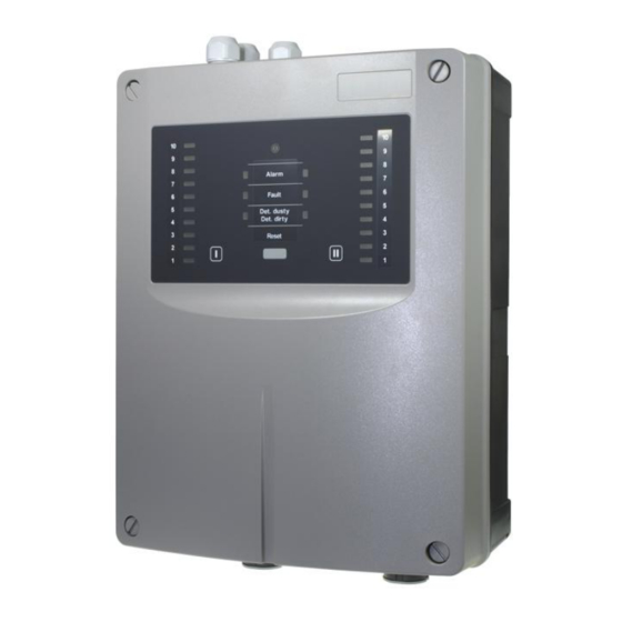
Aspirating smoke detector
Hide thumbs
Also See for ASD 535:
- Mounting and installation (40 pages) ,
- Maintenance manual (24 pages)

Related Manuals for Securiton ASD 535


Summary of Contents for Securiton ASD 535
- Page 1 ASD 535 Aspirating Smoke Detector Application guidelines for deep-freeze ware- houses Beginning with FW version 01.06.01 Securiton AG Alpenstrasse 20 3052 Zollikofen Switzerland T 131 390 c en...
-
Page 3: This Document Constitutes The Application Guidelines For The Use Of The Aspirating Smoke Detector Asd 535 In
This document, T 131 390, is valid only for the product described in technical description T 131 192 in Section 1. This document constitutes the application guidelines for the use of the Aspirating Smoke Detector ASD 535 in deep-freeze warehouses. Technical description T 131 192 is a component of the application guidelines. - Page 4 Description of parts for which there are environmental issues • Description of how devices and their parts have to be disposed of in an environmentally-friendly way • Description of the recycling possibilities 4 / 31 ASD 535, Application guidelines for deep-freeze warehouses, T 131 390 c en...
- Page 5 Rectification / Expansion • 6.1 Cable screw union in set of 10, new Art. no. Correction Lithium battery new Art. no., industrial SD memory cards 5 / 31 ASD 535, Application guidelines for deep-freeze warehouses, T 131 390 c en...
-
Page 7: Table Of Contents
Article numbers and replacement parts Detector housings and accessories Sampling pipe and accessories _________________________________________________________________________________________ Technical data for use in deep-freeze warehouses _________________________________________________________________________________________ List of figures 7 / 31 ASD 535, Application guidelines for deep-freeze warehouses, T 131 390 c en... -
Page 9: General Information
This defines heating element control (relays, subsequent heating time). The response behaviour of the ASD 535 has been tested in compliance with EN 54-20, Class A, B and C. With the ASD 535, deep-freeze warehouses can be monitored in accordance with response classes B and C in compliance with EN 54-20. -
Page 10: Function
Heating element power supply Control of the heating elements is realised by means of a relay (relay 3 of the AMB 35 for ASD 535-1 / -3 or relay of RIM 35 for ASD 535-2 / -4) for each sampling pipe tube network (I / II). The relay has to be programmed using the “ASD... -
Page 11: Planning
These guidelines deal with the application as concerns the fulfilment of EN 54-20 and are intended to ensure technically trou- ble-free operation. The ASD 535 aspirating smoke detector conforms to the requirements of European Standard EN 54-20, Class A to C. The fol- lowing applies: •... -
Page 12: Planning With The "Asd Pipeflow" Calculation Software
Planning with the “ASD PipeFlow” calculation software When setting up a system for deep-freeze warehouses with ASD 535, it is not imperative that the “ASD PipeFlow” calculation software is used. If, however, “ASD PipeFlow” is used, the system limits in Sec. 3.5 must be adhered to. -
Page 13: System Limits For Deep-Freeze Warehouses Without "Asd Pipeflow" Calculation
System limit 1, 2, 3 (tube network length, number of sampling holes) • Third digit Tube networks 1, 2 (number of sampling pipe tube networks on the ASD 535). Example: b22 response class b / system limit 2 / 2 sampling pipe tube networks. -
Page 14: System Limit Table For Planning Without "Asd Pipeflow" Calculation
The specifications are valid with and without detector box (REK, max. 2 units) and small filter-box FBS 25 PC. • If a filter-box is used, it must always be installed within the first 2 m from the ASD 535. 14 / 31... -
Page 15: Non-Normative System Limits Table For Planning Without "Asd Pipeflow" Calculation
± 20% 10 min ± 50% 60 min ± 50% 10 min ± 20% 60 min ± 20% 10 min ± 50% 60 min ± 50% 15 / 31 ASD 535, Application guidelines for deep-freeze warehouses, T 131 390 c en... -
Page 16: Sampling Hole Diameter
If the “ASD PipeFlow” calculation software is used, the sampling hole diameters in the table above (Sec. 3.7) must be used in “ASD PipeFlow”. When calculating the project, only the “Calculate” function may be used in “ASD PipeFlow” (not “Optimize”). 16 / 31 ASD 535, Application guidelines for deep-freeze warehouses, T 131 390 c en... -
Page 17: Sampling Point With Heating
Electrical installation As a rule, the power supply for the heating elements is the same as for the ASD 535 supply from the fire alarm control panel (FACP). However, this is possible only when the ASD 535 is operated with 24 VDC, since otherwise the heating elements would not be able to provide the necessary heating performance. - Page 18 When determining the conductor cross-section, the highest possible power consumption of the ASD 535 during normal opera- tion (after switching on) is the decisive factor. Due to its circuitry design, the ASD 535 has the highest current consumption at minimum supply voltage, i.e. in 24 VDC operation at 18 VDC.
-
Page 19: Power Calculation
Power calculation For maximum power consumption of an ASD 535 with heating elements, besides the ASD type (-1, -2, -3, -4) the number of present sampling points is also decisive. To simplify the calculation, the value of the ASD 535-4 can be used (system with the highest power consumption including one RIM 35). -
Page 20: Mounting And Installation
For this reason, prior to working with these materials it is imperative to read and observe the safety instructions and information provided by the adhesive supplier. A list of the available materials for the sampling pipe (tubes, fittings etc.) for the ASD 535 is available in a separate docu- ment (T 131 194). -
Page 21: Mounting The Detector Housing
Mounting work on the detector housing is best done without fitted smoke sensors. • The smoke sensors are always installed in the detector housing just prior to commissioning the ASD 535. • Depending on the situation (e.g. if there is a long time between mounting and commissioning or if for example the environment is very dusty due to construction), the housing cover should be kept closed until commission- ing the device. -
Page 22: Mounting Positions Of The Detector Housing
Fig. 4 Heating element wiring So that only two silicon Litz wires have to be fed in from the ASD 535 for U-, T- and H-shaped sampling pipes, a CCF 25 cable connection fitting must be installed directly next to the branching point (T piece). There the three wire pairs are gathered to- gether, Fig. -
Page 23: Electrical Connection Of The Silicon Litz Wires
Fig. 8 Mounting the heating resistors Heating resistor centred in the 90° sampling hole Sampling hole Housing of the sampling point Aspiration direction Fig. 9 Centring the heating resistor 23 / 31 ASD 535, Application guidelines for deep-freeze warehouses, T 131 390 c en... -
Page 24: Mounting And Installing The Wcu 535 Wiring Connection Unit
If a small FBS 25 PC filter-box is used, it must always be positioned between the detector housing and WCU 535. The electrical installation of the heating control is performed from the relay in the ASD 535 and is conducted by means of a round cable via cable screw union to the WCU 535 wiring connection unit. -
Page 25: Electrical Connection In The Wcu 535 Wiring Connection Unit
M32 cable screw union for sampling pipe Fig. 11 Design and dimensioned drawing of the WCU 535 Fig. 12 below shows the wiring between ASD 535 and WCU 535 and their electrical connection. Connection cable Connection cable from FACP / power supply... -
Page 26: Commissioning
T 131 192, Sec. 7.3.5. Settings Notice ASD 535 settings are performed based on the specifications in technical description T 131 192, Sec. 4.8. Warning If the configured LS-Ü delay time of 300 s required for the de-icing procedure in accordance with EN 54-20 (switch positions b11 to C32) is not sufficient, it is possible to use switch positions W09 to W48 after consulting with the manufacturer. -
Page 27: Programming The Heating Control
ASD Config 2.X “Channel I” > “Heating control” or “Channel II” > “Heating control”. For the ASD 535 with only one sampling pipe (ASD 535-1 / -3) the relay “ASD Relay 3” or the AMB relay “R3” can be used (Fig. -
Page 28: Checking Heating Control
(e.g. default 2 min). multimeter. 28 / 31 ASD 535, Application guidelines for deep-freeze warehouses, T 131 390 c en... -
Page 29: Article Numbers And Replacement Parts
Detector housings and accessories Designation Article no. Aspirating Smoke Detector ASD 535-1 without smoke level indicator, for 1 smoke sensor (no smoke sensor) 5000623.0101 Aspirating Smoke Detector ASD 535-2 without smoke level indicator, for 2 smoke sensors (no smoke sensor) 5000623.0102... -
Page 30: Technical Data For Use In Deep-Freeze Warehouses
The specified temperature range applies only to use in deep-freeze warehouses. The manufacturer must be consulted if deployment is to be in the condensation range. 30 / 31 ASD 535, Application guidelines for deep-freeze warehouses, T 131 390 c en... -
Page 31: List Of Figures
Fig. 12 Wiring between ASD 535 and WCU 535 ..........................25 Fig. 13 Relay programming for ASD 535-1 / -3 (only one sampling pipe) ..................... 27 Fig. 14 Relay programming for ASD 535-2 / -4 (with two sampling pipes) .................... 27 Fig.
Need help?
Do you have a question about the ASD 535 and is the answer not in the manual?
Questions and answers