
Related Manuals for Securiton ASD 535


Summary of Contents for Securiton ASD 535
- Page 1 ASD 535 Aspirating Smoke Detector Mounting and installation Beginning with FW version 01.08.xx Securiton AG Alpenstrasse 20 3052 Zollikofen Switzerland T 140 333 d en...
- Page 2 The product (hardware, software and technical documentation) is subject to the copyright of the manufacturer. Any prohibited modification, misuse, copying or prohibited sale of this product represents a violation of the copyright and will be legally prose- cuted. Copyright by Securiton AG...
- Page 3 T 131 192 is a component of the mounting and installation instructions. In this document only the points necessary for mounting and installing the ASD 535 are described. The general specifications of the ASD 535 aspirating smoke detector can be found in technical description T 131 192.
-
Page 5: Table Of Contents
Circuitry on selective identification or addressable loop via Al / St relay 3.6.4.3 Circuitry on SecuriPro / SecuriFire / Integral addressable loop from XLM 35 / SLM 35 3.6.5 Open collector outputs ASD 535, Mounting and installation, T 140 333 d en 5 / 40... - Page 6 Table of contents _________________________________________________________________________________________ Article numbers and replacement parts Detector housing and accessories Sampling pipe and accessories _________________________________________________________________________________________ Technical data _________________________________________________________________________________________ List of figures _________________________________________________________________________________________ Document history 6 / 40 ASD 535, Mounting and installation, T 140 333 d en...
-
Page 7: General Information
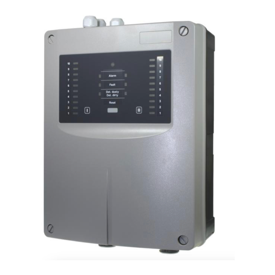
• ASD 535-4 for 2 sampling tubes with smoke level indicator, for 2 smoke sensors. The SSD 535 smoke sensor is used in the ASD 535. It is available in the three following versions and sensitivity ranges: • SSD 535-1 alarm sensitivity range 0.5%/m to 10%/m... -
Page 8: Safety And The Environment
ESD bands for preventing electrostatic discharge are used for grounding persons and for equipotential bonding. 8 / 40 ASD 535, Mounting and installation, T 140 333 d en... -
Page 9: Disposal
= Fire alarm system Fault = Fault = Firmware Flash PROM = Memory component for operating software Flush mounting / = Flush mounted / surface mounted surface mounting ASD 535, Mounting and installation, T 140 333 d en 9 / 40... - Page 10 (Association of Indemnity Insurers, Germany) Vereinigung Kantonaler Feuerversicherungen (Cantonal Fire Insurance Union, Switzerland) = Pre-signal Watchdog = Monitoring of the microcontroller XLM 35 = eXtended Line Module 10 / 40 ASD 535, Mounting and installation, T 140 333 d en...
-
Page 11: Mounting
(76) Space requirement for offset mounting of the housing cover for commissioning and maintenance Fig. 1 Dimensioned drawing, ASD 535 detector housing drilling plan ASD 535, Mounting and installation, T 140 333 d en 11 / 40... -
Page 12: Material For The Sampling Pipe
For this reason, prior to working with these materials it is imperative to read and observe the safety instructions and information provided by the adhesive supplier. A list of the available materials for the sampling pipe (tubes, fittings etc.) for the ASD 535 is available in a separate docu- ment (T 131 194). -
Page 13: Mounting The Detector Housing
The return line can be adapted after removing the air outlet pipe plug on the ASD 535 housing. In this context, see also Sec. 2.4.2 and 2.4.3. The maximum length of the return line must not exceed 20 m. -
Page 14: Opening And Closing The Detector Housing
Notice When mounting several ASD 535 units next to each other, it is important to ensure that the mounting holes are drilled precisely. The device can be moved a maximum of ±2 mm horizontally and vertically to correct the mounting position. -
Page 15: Mounting Positions Of The Detector Housing
I and II entries). Similarly, all cable screw unions are closed. The pipe plug is removed on entry I for ASD 535-1 and -3 and on entry II for ASD 535-2 and -4. For ASD 535-1 and -3 with only one tube network, the pipe plug on entry II is not removed. If there is a return sampling pipe in the monitored area, it can be directly connected to the detector housing in place of the air outlet pipe plugs. -
Page 16: Removal Of The Air Outlet Pipe Plug
• ASD 535-2 = 1 x “A” • ASD 535-3 = 1 x “A” and 1 x “B” • ASD 535-4 = 1 x “A” and 2 x “B” The labelling strips can be pulled out of the control unit by their tabs and after turning over inserted again into the holder. -
Page 17: Mounting Sampling Pipe
• The two glueable materials – PVC and ABS – must not be combined, since different adhesives are used. ASD 535, Mounting and installation, T 140 333 d en 17 / 40... -
Page 18: Mounting With Metal Pipes And Fittings
“work” (slide) in the clips and fastening clamps. A distance of 200 mm (0.2 m) should be maintained between the last clip or fastening clamp to the end cap. 18 / 40 ASD 535, Mounting and installation, T 140 333 d en... -
Page 19: Mounting The Sampling Pipe
Fig. 8 Vertical sampling pipe ASD 535 0,2 m 0,2 m End cap T-piece 0,2 m Clip 0,2 m Clip 90º arc Fig. 9 90° bend, branching point ASD 535, Mounting and installation, T 140 333 d en 19 / 40... -
Page 20: Mounting For Equipment Monitoring
Further, the same guidelines as described in Sec. 2.5.6 apply. All air outlet openings of the monitoring devices have to be used for equipment monitoring. Please note that an ASD 535 can be fitted with a maximum of six sampling fixtures. -
Page 21: Transition To Flexible Tube
Angle or Flexible tube coupling Sleeve Ø 16/21 mm = glued (PVC or ABS glue) = screwed = snapped in Fig. 11 Transition from fitting to flexible tube ASD 535, Mounting and installation, T 140 333 d en 21 / 40... -
Page 22: Making The Sampling Holes
The sampling funnels are fastened to the tube of the sampling fixture and adjusted on the previously drilled sampling holes as described in Fig. 14. Sampling funnel Funnel opening Support rail Fig. 14 Using sampling funnels 22 / 40 ASD 535, Mounting and installation, T 140 333 d en... -
Page 23: Mounting Sampling Stubs For The Ceiling Duct
• The maximum length of the flexible tube must False ceiling not exceed 1.5 m. Sampling hole Fig. 15 Mounting the ceiling duct ASD 535, Mounting and installation, T 140 333 d en 23 / 40... -
Page 24: Mounting Filter Box, Filter Unit, Dust Trap, Dust Separator, Water Separator
FBL 25 units instead of FBL 25 (all other accessories as show) Dust Retaining Box DRB 25 Dust Retaining Box DRB 25 Fig. 16 Mounting accessory parts 24 / 40 ASD 535, Mounting and installation, T 140 333 d en... -
Page 25: Installation
Cable screw unions which are not used must be replaced with blind plugs (mounting set) in order to maintain the IP 54 protection class. Use in compliance with UL 268: When using the ASD 535 in compliance with UL 268, special 1/2“ and 3/4“ •... -
Page 26: Deploying Smoke Sensors
(big flat cable connecter) and to the AMB 35 Main Board (small flat cable connector). The insect protection screens and lock clamps are not fitted to smoke sensor chamber II on the ASD 535-1 and -3 (only one smoke sensor). -
Page 27: Installing Expansion Modules Xlm 35, Slm 35, Rim 35, Mcm 35, Sim
Notice, XLM 35 installation With the installation of the use of an XLM 35, the ASD 535 meets the requirements in compliance with EN 54-17 (short-circuit isolation). To ensure that the required identification is recognisable in compliance with EN 54-17, the supplied identification sign must be easily visible outside on the ASD housing and attached in the immediate vicinity of the ASD rating plate (same side) when the XLM 35 is installed. -
Page 28: Electrical Connection
Caution: For system monitoring – for terminals “Alarm I”, “Alarm II” and “Fault”, do not use looped wire un- der terminals. Break wire run to provide monitoring of connections. 28 / 40 ASD 535, Mounting and installation, T 140 333 d en... -
Page 29: Terminal Assignment Of Amb 35 Main Board
(available at a later date) 0 V power supply “S” Notice The “Fault” relay has picked up in the normal state contact Te. 12/10 closed, 12/11 open (ASD 535 under voltage; no fault present). AMB 35 internal connections... -
Page 30: Extended Line Module Xlm 35 / Securiline Module Slm 35 Terminal Assignment
“ASD Config” configuration software. If two RIM 35 devices are deployed in the ASD 535-1 or -3, the relays of the second RIM 35 are not config- ured with default criteria. The required programming must be performed with the “ASD Config” configuration software. -
Page 31: Connection Variants
In all cases the ASD 535 must have an emergency power supply (country-specific, e.g. compliant with EN 54-4). 3.6.1 Power supply The ASD 535 must always have emergency power supply. -
Page 32: Control
Installation 3.6.3 Control The ASD 535 units connected to a FACP are controlled according to the detection zone mapping using the FACP states “Zone ON/OFF” and “Reset”. Two possibilities are available: • Control via supply voltage (auxiliary relays in the ASD power supply line) •... -
Page 33: Control Via The "Reset External" Input
= “Zone Off / Reset” Al II try via the XLM 35 / SLM 35 on the ASD 535. The function types listed above are determined by the FACP from OC output via relay (or PMR 81), supply from FACP technology in use. -
Page 34: Wiring The Facp Line
Circuitry on zone detection via Al / St relay • For circuitry on zone detection lines, actuation of the auxil- ASD 535 with one smoke sensor, connected on one line iary relay is, as a rule, from the line plus. A condition for FACP... -
Page 35: Circuitry On Selective Identification Or Addressable Loop Via Al / St Relay
There are two switches – S1 and S2 – on the SLM 35 that have to be differently set depending on the use of the ASD 535. • When operating an ASD 535-2 and ASD 535-4 (with 2 smoke sensors), two addresses are allocated on the SLM 35. •... -
Page 36: Open Collector Outputs
Alarm II (-) (e.g. relays) can be connected to the open collector outputs. In ASD 535-1 and -3 the output on terminal 8 is not “Alarm II” Fig. 26 Wiring the OC outputs but rather freely programmable (it is always identical with the programming on relay 3 of the AMB 35). -
Page 37: Article Numbers And Replacement Parts
Article numbers and replacement parts Detector housing and accessories Designation Article no. ASD 535-1 without smoke level indicator, for 1 smoke sensor (without smoke sensor) 5000623.0101 ASD 535-2 without smoke level indicator, for 2 smoke sensors (without smoke sensor) 5000623.0102 ASD 535-3 with smoke level indicator, for 1 smoke sensor (without smoke sensor) 5000623.0103... -
Page 38: Technical Data
Lower or higher temperature ranges are possible after consulting with the manufacturer. The manufacturer must be consulted if deployment is to be in the condensation range. 38 / 40 ASD 535, Mounting and installation, T 140 333 d en... -
Page 39: List Of Figures
List of figures List of figures Fig. 1 Dimensioned drawing, ASD 535 detector housing drilling plan ....................11 Fig. 2 Opening, closing and fastening the detector housing ......................... 14 Fig. 3 Mounting position and pipe entries on the detector housing ....................... 15 Fig. -
Page 40: Document History
3.5.3 Text corrections (“Sampling tube” “Sampling pipe”) Correction Article number for AMB 35-x corrected Correction “Sound pressure level” instead of “noise level“, value Correction specification corrected 40 / 40 ASD 535, Mounting and installation, T 140 333 d en...
Need help?
Do you have a question about the ASD 535 and is the answer not in the manual?
Questions and answers