
Related Manuals for Securiton ASD 531


Summary of Contents for Securiton ASD 531
- Page 1 ASD 531 Aspirating Smoke Detector Technical description as of firmware version 01.00.08 Securiton AG Alpenstrasse 20 3052 Zollikofen Switzerland T 140 416 en...
- Page 3 First edition 15.10.2015 Bmi/ksa Notice Validity for production version and firmware version The following documentation is applicable only to the ASD 531 aspirating smoke detector with the following pro- duction version and firmware version: Production version Firmware version from 151015 from 01.00.08...
- Page 4 RIM 36 T 140 364 de / en / fr / it / es / pt / sv AFU 32 Aspirating Fan Unit mounting instructions T 140 426 Multilingual (EDFI) 4 / 105 ASD 531, Technical description, T 140 416 en...
- Page 5 You may also send them back to the seller by post. The seller will refund the postage when you return your old batteries. ASD 531, Technical description, T 140 416 en 5 / 105...
- Page 7 Document history Document history First edition Date 15.10.2015 ASD 531, Technical description, T 140 416 en 7 / 105...
-
Page 9: Table Of Contents
Data logging on the SD memory card 2.2.16 Reset types 2.2.16.1 State reset 2.2.16.2 Hardware reset 2.2.16.3 Initial reset _________________________________________________________________________________________ Design Mechanical Electrical Hardware / firmware List of materials / components Packaging ASD 531, Technical description, T 140 416 en 9 / 105... - Page 10 Mounting the sampling hole clips and maintenance clips 5.5.10 Mounting the sampling funnel 5.5.11 Mounting sampling stubs for a ceiling bushing 5.5.12 Mounting the filter-box, filter unit, dirt trap box, dust retaining box, water retaining box 10 / 105 ASD 531, Technical description, T 140 416 en...
- Page 11 8.5.4 Reading out the event memory 8.5.4.1 Interpretation of the event memory 8.5.4.2 Event groups 8.5.4.3 Event codes within event groups 8.5.5 Operation and displays on the XLM 35 ASD 531, Technical description, T 140 416 en 11 / 105...
- Page 12 Use under extreme conditions 11.3 Use of detector boxes _________________________________________________________________________________________ Article numbers and spare parts 12.1 Detector housings and accessories 12.2 Sampling pipe and accessories _________________________________________________________________________________________ Technical data _________________________________________________________________________________________ List of figures 12 / 105 ASD 531, Technical description, T 140 416 en...
-
Page 13: General
Purpose The ASD 531 aspirating smoke detector has the task of continuously taking air samples via a sampling pipe tube network from a monitored area and feeding the samples to a smoke sensor. Thanks to this detection method and the product’s excellent... -
Page 14: Uses And Applications
Equipment monitoring: EDP systems, electrical distributors, switch cabinets, etc. The ASD 531 can also be deployed in areas where normally conventional point detectors are used. Local regulations and pro- visions must be observed from case to case. The response behaviour of the ASD 531 has been tested in compliance with EN 54-20, Class A, B and C. - Page 15 Verband der Schadenversicherer (Association of Indemnity Insurers, Germany) Vereinigung Kantonaler Feuerversicherungen (Cantonal Fire Insurance Union, Switzerland) = Pre-signal Watchdog = Monitoring of the microcontroller XLM 35 = eXtended Line Module ASD 531, Technical description, T 140 416 en 15 / 105...
-
Page 16: Product Identification
General Product identification For identification purposes, the ASD 531 and its units have rating plates or identification plates. The following product identifications apply: Rating plate on the ASD 531 and identification on the packaging Manufacturer Type designation 3052 Zollikofen / Switzerland... -
Page 17: Smoke Sensors Used
The use of third-party detectors voids the ASD 531 approval issued by the manufacturer. The ASD 531 is fitted with the SSD 31 smoke sensor by the manufacturer. It has an alarm sensitivity range of 0.02%/m to 10%/m. -
Page 18: Function
A fan failure, blockage of the sampling holes or pipe breakage must be communicated to the fire alarm control panel in the form of a fault signal. This condition is satisfied by the airflow monitoring of the ASD 531. -
Page 19: Electrical Functional Principle
2.2.1 Power supply The operating voltage of the ASD 531 is +14 to +30 VDC. On the AMB 31 Main Board, 5 VDC of the operating voltage is di- verted for internal voltage use. The operating voltage is monitored on the AMB 31 for undervoltage. If the operating voltage falls below 13 VDC (+0 / –0.3 VDC), the ASD 531 triggers an undervoltage fault. -
Page 20: Fan Control
A specially designed circuit therefore ensures that the fan cannot exceed a specific maximum power consumption in its start- up phase. When the ASD 531 is switched on, the computer-controlled fan speed starts up slowly. After the fan has been pow- ered up, the speed is kept constant. -
Page 21: Programming / Operation
(on “Reset external” input of the ASD 531). Events triggered on the ASD 531 can be reset locally using the “Reset” key on the control unit or by briefly actuating the “Re- set External” input. The reset is possible only if the triggered event is no longer pending (e.g. smoke sensor no longer has smoke). -
Page 22: Displays
Rel. 5 Sampling tube blockage, sampling tube interruption, fan fault Notice The “Fault” relay has picked up in the release state contact Te. 12/10 closed, 12/11 open (ASD 531 under voltage; no fault event present). 22 / 105... -
Page 23: Outputs
(opto-isolator). It can be actuated both on the “plus” and on the “minus” side. The input operates in the 5 to 30 VDC range and has a pulse bandwidth of 0.5 to 10 s. When a continuous signal is applied for longer than 20 s, the ASD 531 is deactivated (fault state) (see also Sec. -
Page 24: Airflow Monitoring
Smoke sensor monitoring The smoke sensor used on the ASD 531 is monitored on the AMB 31 Main Board. A failure of the sensor electronics, a dusty or dirty smoke sensor is registered as an event code and displayed as a state or fault. Likewise, the connection line between the smoke sensor and the AMB 31 is monitored and a fault is signalled if there is a failure. -
Page 25: Fault Triggering
Fault triggering If a fault occurs on the ASD 531, the “Fault” relay is de-energised and the “Fault” display is activated. With the SD memory card, the fault profile can also be used in the event of a fault (see also Sec. 8.5.4.3 and 10.3.1). The following events trigger a fault (list is incomplete): •... -
Page 26: Reset Types
A hardware reset is triggered if there is a brief interruption in the supply voltage or if the “HW reset” key is briefly pressed on the AMB 31 (see also Fig. 40 and Fig. 44). This restarts the ASD 531. The fan stops and then slowly starts up again (start-up control). -
Page 27: Design
There is one chamber for the smoke sensor in the detector housing. The air channel through the smoke sensor and fan are separated from the other parts inside the detector housing; this means the ASD 531 is able to remain fully operational during commissioning and maintenance work even when the housing cover is open. -
Page 28: Fig. 4 Mechanical Design
4 x fastening holes Connection for sampling pipe Housing cover Labelling strip for state display 4 x rotary quickrelease locks Fig. 4 Mechanical design 28 / 105 ASD 531, Technical description, T 140 416 en... -
Page 29: Electrical
Design Electrical The electrical design of the ASD 531 includes the following (may vary depending on the device version): • AMB 31 Main Board • Smoke sensor (SSD 31) • • Air flow sensor • Additional modules XLM 35, RIM 36. -
Page 30: Hardware / Firmware
Notice A version change or extension of the ASD 531 firmware does not imply a right to an upgrade or new release for existing ASD 531 systems. -
Page 31: List Of Materials / Components
T 131 194. Materials from other sources may be used only if the manufacturer’s written consent has been obtained. A special tool is required for mounting and handling the ASD 531 (Torx screws). Please refer to the list in Sec. 5.1. Packaging The detector housing is delivered in a customised cardboard sleeve sealed with adhesive tape. -
Page 32: Planning
Standards, regulations, guidelines, approvals Sec. 4 “Planning” below is a guideline for planning the ASD 531 aspirating smoke detector. These guidelines address the di- rect application only insofar as it applies to compliance with EN 54-20 and is required to ensure technically trouble-free opera- tion. -
Page 33: System Limits
System limits The use of an ASD 531 aspirating smoke detector is subject to the system limits listed below and compliance with EN 54-20 requirements. Depending on the planning process, the system limits as set out in Sec. 4.4 also apply. -
Page 34: Values Table For Planning With "Asd Pipeflow
0.593 0.071 4.285 0.515 0.062 3.721 0.447 0.054 3.231 0.388 0.047 2.805 0.337 0.041 2.436 0.293 0.035 2.115 0.254 0.031 1.836 0.221 0.027 1.594 0.192 0.023 1.384 0.166 0.020 34 / 105 ASD 531, Technical description, T 140 416 en... -
Page 35: Planning Without "Asd Pipeflow" Calculation
4.3.2 Planning without “ASD PipeFlow” calculation If planning is performed without “ASD PipeFlow”, a number of switch settings in the ASD 531 are saved with pre-defined val- ues which are necessary for actuation in compliance with EN 54-20, Class A–C. -
Page 36: Principles Of Space Surveillance
The following principles apply to space monitoring: • The number and arrangement of the ASD 531 units are based on the size of the space. • In general the monitoring areas are the same as for point-type detectors. Directives that apply to specific ob- jects –... -
Page 37: Types Of Sampling Pipe Layouts For Space Surveillance
±10%). This concerns tube layout as well as the spacing of sampling holes. Farthest sampling hole Sampling holes ASD 531 ASD 531 ASD 531 ASD 531 E-shaped H-shaped U/T-shaped I-shaped Fig. 8 Examples of planning without “ASD PipeFlow” calculation ASD 531, Technical description, T 140 416 en 37 / 105... -
Page 38: System Limits For Space Surveillance Without "Asd Pipeflow" Calculation
A, B, C (A = highly sensitive, B = sensitive, C = standard) • Rotary switch “Holes” number of sampling holes 1 to C (A = 10, B = 11, C = 12) 38 / 105 ASD 531, Technical description, T 140 416 en... -
Page 39: System Limits For Planing Without "Asd Pipeflow" Calculation
The overall length of the sampling pipe must not exceed the system limits as set out in Sec. 4.2.1. • The filter-box / filter unit and water retaining box must always be mounted within the first 2 m of the ASD 531. 4.4.4.3 Sampling holes for planning without “ASD PipeFlow”... -
Page 40: Maintenance Sampling Hole
A maintenance sampling hole is not included in the calculations set out in Sec. 4.4.4.2. • The maintenance sampling hole is used only for maintenance purposes, to test the ASD 531 for alarming. • In normal operation (no maintenance), the maintenance sampling hole must be sealed off with adhesive tape or a “maintenance clip”... -
Page 41: Equipment Monitoring
4.5.1 Equipment monitoring applications Equipment monitoring applications using the ASD 531 are additional monitoring applications to space surveillance. Equipment monitoring directly involves monitoring an object (machine, device or equipment). The following objects are typical examples of an ASD 532 monitoring: •... -
Page 42: Examples Of Sampling Pipe Layouts For Equipment Monitoring
On objects with a high air-flow rate (strong ventilation), the sampling holes should be fitted with SF ABS sam- pling funnels for optimal smoke detection. • Symmetry is not required for the sampling fixture. 42 / 105 ASD 531, Technical description, T 140 416 en... -
Page 43: Air Recirculation
Air recirculation Open pipe end Sampling holes End cap max. 20 m Pipe network ASD 531 Climate zone B Climate zone A Fig. 12 Air recirculation for differing climate zones ASD 531, Technical description, T 140 416 en 43 / 105... -
Page 44: Settings
The definitions of the pre-defined settings and the operator structure are found in Sec. 4.4.4.2, 7.2.1 and 8.3. Depending on the use of the ASD 531, it may be necessary to make adjustments to the airflow monitoring using the “ASD Config” configuration software. These adjustments relate merely to the size of the monitoring window (pipe breakage/pi- pe blockage) and the fault delay time (time until the exceeded monitoring window is reported as a fault). -
Page 45: Electrical Installation
In areas with high-energy devices and installations (generators, power plants, railway facilities, X-ray equipment, etc.). Outside buildings. If screening is used, the cable screening in the ASD 531 is to be connected to an additional support terminal. The cable screening must not be connected to the minus or ground terminal of the AMB 31. -
Page 46: Determining The Conductor Cross-Section
When determining the conductor cross-section, the highest possible power consumption by the ASD 531 during normal opera- tion (after switching on) is the decisive factor. Due to its circuitry design, the ASD 531 has the highest power consumption at the minimum supply voltage, i.e. at 14 VDC. -
Page 47: Restrictions
Planning Restrictions Notice The following restrictions apply to the use and application of the ASD 531. For other solutions, please consult the manufacturer. General information and space surveillance: • The sampling holes of the tube network and the detector housing must be in the same climate zone (pres- sure/temperature zone) (sampled air may have to be recirculated to the other climate zone). -
Page 48: Environmental Influences
Environmental influences Danger On the basis of the conducted tests, the ASD 531 may be used in an environment that is within the scope of the type approvals. The environmental conditions as described in Sec. 13 must also be observed. Non-observance can negatively impact proper functioning of the ASD 531. -
Page 49: Mounting
• Replacing the aspirating fan unit Torx screwdriver T15 Dimensioned drawing / drilling plan for the detector housing 20.5 20.5 Fig. 14 Detector housing dimensioned drawing and drilling plan ASD 531, Technical description, T 140 416 en 49 / 105... -
Page 50: Material For The Sampling Pipe
For this reason, prior to working with these materials it is imperative to read and observe the safety in- structions and information provided by the adhesive supplier. A list of the available materials for the sampling pipe (pipes, fittings etc.) for the ASD 531 is available in a separate docu- ment (T 131 194). -
Page 51: Mounting The Detector Housing
The return line can be adapted after removing the air outlet pipe plug on the ASD 531 housing. See also under Sec. 4.5, 5.4.2 and 5.4.3. The maximum length for the return line must not exceed 20 m. -
Page 52: Opening And Closing The Detector Housing
Notice When mounting several ASD 531 units next to one another, make sure that the mounting holes are drilled pre- cisely. The device can be shifted by a maximum of ±2 mm horizontally and vertically to correct its mounting posi- tion. -
Page 53: Mounting Positions For The Detector Housing
The air outlet pipe plug (with openings) is to be fitted to the air outlet opening only. • The pipe plugs must not be glued in the ASD housing (plug-in connector). ASD 531, Technical description, T 140 416 en 53 / 105... -
Page 54: Removing The Air Outlet Pipe Plug
Open the detector housing to turn the labelling strips. Use the tab to pull the labelling strip out of the cover, turn it over, and then re-insert it into its compartment. Fig. 18 Turning the labelling strips 54 / 105 ASD 531, Technical description, T 140 416 en... -
Page 55: Mounting The Sampling Pipe
Notice The two glueable materials – ABS and PVC – must not be combined, since different adhesives are used. ASD 531, Technical description, T 140 416 en 55 / 105... -
Page 56: Mounting With Metal Pipes And Fittings
(20°C). It is therefore essential to ensure that the sampling pipe is able to “move” (slide) inside the clips/pipe clamps. A distance of 100 mm (0.1 m) must therefore be maintained between the last clip or fastening clamp and the end cap. 56 / 105 ASD 531, Technical description, T 140 416 en... -
Page 57: Mounting The Sampling Pipe
Vertical sampling pipe Fig. 21 Vertical sampling pipe ASD 531 0.2 m 0.2 m End cap T-piece 0.2 m Clip 0.2 m Clip 90° arc Fig. 22 90° bend, branching point ASD 531, Technical description, T 140 416 en 57 / 105... -
Page 58: Mounting For Equipment Monitoring
Support rail Double-sided adhesive tape Movement in the support rail M4 threaded plate Sampling fixture EDP cabinet Ventilation slot Fig. 23 Screw-free fastening of a sampling fixture 58 / 105 ASD 531, Technical description, T 140 416 en... -
Page 59: Transition To A Flexible Tube
Angle or Flexible tube coupling Sleeve Ø 16/21 mm = glued (PVC or ABS glue) = screwed = snapped in Fig. 24 Transition from fittings to flexible tube ASD 531, Technical description, T 140 416 en 59 / 105... -
Page 60: Creating The Sampling Holes
The sampling funnels are fastened to the tube and adjusted on the previously drilled sampling holes, Fig. 27. Sampling funnel Funnel opening Support rail Fig. 27 Using sampling funnels 60 / 105 ASD 531, Technical description, T 140 416 en... -
Page 61: Mounting Sampling Stubs For A Ceiling Bushing
M25 threaded ring The maximum length of the flexible tube must not False ceiling exceed 1.5 m. Sampling hole Fig. 28 Mounting the ceiling bushing ASD 531, Technical description, T 140 416 en 61 / 105... -
Page 62: Mounting The Filter-Box, Filter Unit, Dirt Trap Box, Dust Retaining Box, Water Retaining Box
MV 25 ADB 01A Filter box FBL 25 Filter box FBL 25 Dust Trap Box Dust Retaining Box DTB 25 DRB 25 Fig. 29 Mounting accessory parts 62 / 105 ASD 531, Technical description, T 140 416 en... -
Page 63: Installation
Cable entry Danger Make sure the power is disconnected for all connection and wiring work on the ASD 531. There are two M20 cable screw unions in the detector housing for feeding in the electrical installation. If needed, an additional two cable screw unions (1 x M20, 1 x M25) can be fitted in two reserve holes (blind plugs). -
Page 64: Deploying Smoke Sensors
Deploying smoke sensors The ASD 531 ships with the smoke sensor already fitted. The smoke sensor has to be removed from the detector housing for the installation of the ASD (release the two lock clamps); however it should be left inside its protective packaging until the de- finitive commissioning. -
Page 65: Installing Additional Modules Xlm 35, Rim
Danger Inside the detector housing the lines should be fed to the terminals using the shortest possible route. Reserve loops via the main board are to be avoided (EMC). ASD 531, Technical description, T 140 416 en 65 / 105... -
Page 66: Terminal Assignment Main Board Amb 31
Fig. 33 and Fig. 35 External reset input – (opto-isolator input) Notice The “Fault” relay has picked up in the release state contact Te. 10/8 closed, 10/9 open (ASD 531 under voltage; no fault event present). 66 / 105... -
Page 67: Terminal Assignment For Extended Line Module Xlm 35
Smoke sensor fault / Rel. 4 “NC” Dust smoke sensor / Smoke sensor dirt “COM” “NO” Fan fault / Rel. 5 “NC” Sampling tube / Pipe breakage sampling tube “COM” ASD 531, Technical description, T 140 416 en 67 / 105... -
Page 68: Connection Variants
The connection variants are determined by the possible line and FACP technologies used. For more information on connecting alarm transmitters, line monitoring elements, etc., please contact the manufacturer and/or supplier of the fire alarm system. In all cases the ASD 531 must have an emergency power supply compliant with EN 54-4. 6.6.1 Power supply... -
Page 69: Control
Installation 6.6.3 Control The ASD 531 units connected to an FACP are controlled according to the detection zone mapping using the FACP states “Zone ON/OFF” and “Reset”. Two possibilities are available: • Control via supply voltage (auxiliary relays in the ASD power supply line);... -
Page 70: Control Via "Reset External" Input
Warning from OC output of control module, supply from FACP Caution: When control is via the “Reset external” Supply input, the ASD 531 is supplied with voltage even FACP Reset if the zone (FACP) is switched off. Line/loop OC output... -
Page 71: Connection To The Facp Line
ASD 531 FACP PMR 81 or power supply relay Reset Line 1 2 14 15 Inputs Alarm transmitter Fig. 37 Connection on selective identification or ad- dressable loop ASD 531, Technical description, T 140 416 en 71 / 105... -
Page 72: Connection To Securifire / Integral Addressable Loop From Xlm 35
X2 / Loop 1 2 14 G2 L2 state query and the control of the ASD 531 take place directly between the XLM 35 and the addressable loop. Maximum connectible XLM 35 units: Fig. 38 Connection from XLM 35 (see also notice below) -
Page 73: Commissioning
Before switching on the ASD power supply, ensure that all fire incident controls and remote alerting from the ASD 531 are blocked or deactivated. • Immediately before switching on the ASD 531 for the first time, remove the isolating strip from the lithium bat- tery (AMB 31). •... -
Page 74: Programming
• Switch positions for the settings based on application of “ASD PipeFlow”. If the ASD 531 is operated in BasiConfig, only the corresponding switch position A/1 to C/C as described in Sec. 4.4.4.1 are to be selected. In systems where the sampling pipe planning was performed with the “ASD PipeFlow” calculation software, the response sen- sitivities of the smoke sensor calculated by “ASD PipeFlow”... -
Page 75: Configuration Options
The information on operation and display elements necessary for startup can be found in Fig. 41. Warning Before the ASD 531 is switched on, all the precautions required for operation as described in Sec. 7.1 must be fulfilled. ASD 531, Technical description, T 140 416 en... -
Page 76: Commissioning Procedure
Setting the alarm threshold without “ASD Pipeflow” calculation The following describes the procedure for setting the ASD 531 to one of the switch positions with fixed parameters A/1 to CC. Example: The ASD 531 is to respond in compliance with EN 54-20, Class B. The sampling pipe is U-shaped with 3 sampling holes per sampling branch. -
Page 77: Setting The Alarm Threshold With "Asd Pipeflow" Calculation
The following work flow describes the procedure for setting air flow tolerance and delay time of the ASD 531. Example: ASD 531 is to trigger a fault if there is a deviation of ±30% after 20 min. Perform the settings as described in Sec. -
Page 78: Set Date And Time
Isolate device This function is used to place the ASD 531 in an isolated state. In this way test alarms can then be triggered on the ASD 531 without activating superordinate systems (FACP) (relays, OC outputs, XLM do not trigger). When the “Isolate” function is switched on, a fault is triggered on the ASD and forwarded to the superordinate centre. -
Page 79: Logging Off Additional Modules Xlm 35, Rim 36 And The Sd Memory Card
Switch device inactive This function switches off the fan and sensor of the ASD 531. The ASD 531 is then no longer capable of an alarm. An inactive ASD triggers a fault and signals the superordinate unit (FACP) accordingly. On the ASD the “Fault” LED is then continuously lit. -
Page 80: Re-Programming
The parameters are configured ex factory with default states and values so that the triggering properties comply with EN 54-20. Changing the parameters may result in non-compliance with EN 54-20. Adjustments and modifi- cations to the ASD 531 may be carried out only by the manufacturer or by trained technicians. 7.4.1... -
Page 81: Download New Firmware To The Asd
With the conductor cross-section determined and installed as described in Sec. 4.8.2, this voltage range must always be avail- able at the end of the electrical installation – i.e. at the ASD 531 – to ensure that the ASD 531 is able to operate fault-free (see also Sec. -
Page 82: Reading The Airflow
According to EN 54-20 a change in the airflow that is greater than ±20% must be reported as a fault. After an ini- tial reset, the airflow shows 100% in the ASD 531 aspirating smoke detector when the sampling pipe is correct and clean. -
Page 83: Testing And Checking
In addition to the sampling pipe checks set out in Sec. 7.1, the correct transmission of alarms (zone and line) on the FACP is to be checked by triggering faults or alarms on the ASD 531. These tests are to be entered in the commissioning protocol (see also Sec. -
Page 84: Test Triggerings
Notice about test triggerings Fire incident control and remote alerting must be blocked or deactivated on the superordinate FACP. Reset the ASD 531 between each check (preferably on the FACP, as a reset on the ASD does not reset the FACP). -
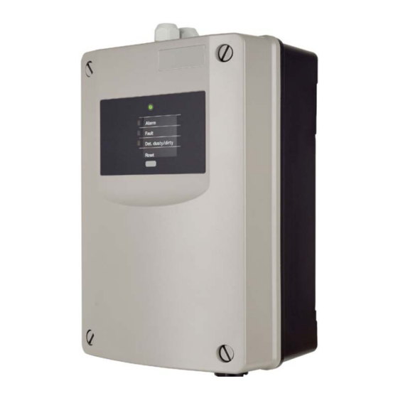
Page 85: Operation
Fig. 44 View of the operation and display elements The control unit has a “Reset” key for resetting triggered events (alarms/faults) directly on the ASD 531. Three rotary switches and two DIP switches are inside the device on the AMB 31 main Board as well as three LEDs. -
Page 86: Functional Sequence Of Operation
(on “Reset external” input of the ASD 531). Events triggered on the ASD 531 can be reset locally using the “Reset” key on the control unit or by briefly actuating the “Re- set External” input. The reset is possible only if the triggered event is no longer pending (e.g. smoke sensor no longer has smoke). -
Page 87: Reset
(e.g. smoke level in the smoke sensor is once again below the trigger threshold, or a fault event is rectified). As a result of the reset, the ASD 531 continues to run “normally” and the fan does not stop. -
Page 88: Indicators On The Amb 31 Main Board
83 days. The log files can be opened in Excel and the data processed with the diagram assistant to create charts. Events: All events occurring in the ASD 531 are written to the Event-Files (*.aev file). After 64,000 events a new Event-File created automatically. -
Page 89: Event Groups
Smoke sensor switched on from FACP (SecuriFire – Integral) G01, general events, part 2 Date, time set Event memory deleted G03, general events, part 3, configuration changes G04, general events, part 4, reset results SecuriLine External ASD 531, Technical description, T 140 416 en 89 / 105... - Page 90 RIM fault, too many RIMs G71, XLM faults XLM fault, lacking or defective XLM fault, too many XLMs G73, SD memory card faults SD memory card fault, missing or defective 90 / 105 ASD 531, Technical description, T 140 416 en...
-
Page 91: Operation And Displays On The Xlm 35
LED 2 (green) State ASD 531 <> XLM 35 Not lit No power supply from AMB 31 Flashes (normal operation) Supply from AMB 31 OK, communication XLM <> ASD OK ASD 531, Technical description, T 140 416 en 91 / 105... -
Page 92: General
Servicing, maintenance or inspection work on the ASD 531 may be necessary after an event (fire, fault). If a detector housing has to be replaced due to a defect, the new ASD 531 is to undergo the same procedure as a first-time commissioning (initial reset required). -
Page 93: Maintenance Checks And Function Checks
Check the air outlet for any dirt or dirt and clean if necessary. If the ASD 531 is used for equipment monitoring and plug-in transitions from rigid to flexible pipe sections are in place, check that the transitions are correctly seated (no leakage). -
Page 94: 4 / 105 Asd 531, Technical Description, T 140 416 En
ASD 531 can no longer trigger an alarm. 14. If maintenance or repair work was carried out on the ASD 531 (including the sampling pipe) as a result of servicing check, a new initial reset may be necessary (see Sec. -
Page 95: Replacing Units
The connection cable must be placed in B. Warning After replacing the aspirating fan unit, it is imperative to carry out a new initial reset (see Sec. 7.3.5). Fig. 46 Removing the aspirating fan unit ASD 531, Technical description, T 140 416 en 95 / 105... -
Page 96: Replacing The Air Flow Sensor
After replacing the AMB 31 it is imperative to carry out a new initial reset (see Sec. 7.3.5). Likewise, all customer- specific configurations and project-specific settings from the “ASD PipeFlow” configuration software must be car- ried out once again. To do so, proceed according to Sec. 7.3.1. 96 / 105 ASD 531, Technical description, T 140 416 en... -
Page 97: Disposal
Devices, sampling pipes or parts thereof that are no longer used should be disposed of in an environmentally- friendly manner. The manufacturer of the ASD 531 is obliged to take back any devices and sampling pipes that are defective or no longer used, for eco-friendly disposal. For this purpose the manufacturer has implemented a monitored and ap- proved disposal system. -
Page 98: Faults
ASD 531. • All repairs and troubleshooting measures are to be documented. • The ASD 531 must undergo a function check following a repair or troubleshooting measure. 98 / 105 ASD 531, Technical description, T 140 416 en... -
Page 99: Finding And Rectifying Faults
EEPROM access error, smoke sensor Smoke sensor • Smoke sensor defective replace EEPROM invalid data, smoke sensor Smoke sensor • Smoke sensor defective replace Manufacturing, smoke sensor Smoke sensor ASD 531, Technical description, T 140 416 en 99 / 105... - Page 100 • Carry out new initial reset • Observe sampling pipe specifications Invalid parameters for initial reset Sampling pipe specifications • Initial reset was interrupted (by “ASD Off”) new initial reset 100 / 105 ASD 531, Technical description, T 140 416 en...
- Page 101 • Isolation strip still present on the lithium Clock fault Lithium battery battery remove. Clock setting • Clock is not set • Lithium battery defective replace ASD 531, Technical description, T 140 416 en 101 / 105...
-
Page 102: Options
(T 135 422). Warning The REK 511 detector box cannot be operated from the ASD 531. The REK 511 detector box has to be con- nected directly from the FACP using an appropriate addressing module. When using detector boxes, it may be necessary to carry out a sampling pipe calculation using “ASD PipeFlow”... -
Page 103: Article Numbers And Spare Parts
12.2 Sampling pipe and accessories The article numbers of all the available parts for the sampling pipe (tubes, fittings, etc.) are listed in a separate document (T 131 194). ASD 531, Technical description, T 140 416 en 103 / 105... -
Page 104: Technical Data
280 70 05 / anthracite violet 300 20 05 Approvals EN 54-20 ASD 531-1 dimensions (W x H x D, without/with packaging) 195 x 333 x 140 / 215 x 355 x 160 Weight ASD 531-1 (without/with packaging) 1,950/2,250 Notice ... -
Page 105: List Of Figures
Fig. 44 View of the operation and display elements ..........................85 Fig. 45 XLM 35 operation and display ..............................91 Fig. 46 Removing the aspirating fan unit .............................. 95 Fig. 47 Removing the air flow sensors ..............................96 ASD 531, Technical description, T 140 416 en 105 / 105...
Need help?
Do you have a question about the ASD 531 and is the answer not in the manual?
Questions and answers