Paxton Switch2 Installation Manual
Hide thumbs
Also See for Switch2:
- Quick start manual (4 pages) ,
- How to program (4 pages) ,
- How to install (3 pages)
Table of Contents
Advertisement
Advertisement
Table of Contents

Related Manuals for Paxton Switch2


Summary of Contents for Paxton Switch2
- Page 1 Switch2 Installation Manual ins-145 24/10/2007...
-
Page 2: Table Of Contents
System overview .................. 4 Chapter 2 About…..............5 Operating modes .................. 5 TOUCHLOCK ..................5 CARDLOCK & PROXIMITY............6 PROXIMITY KP series keypads ..........6 Switch2 Control Unit ................6 Inputs ....................6 Outputs ..................7 Enclosure Options ................. 7 Power Requirements .............. - Page 3 TOUCHLOCK system................19 Programming Switch2 ............... 19 Default Settings ................20 CARDLOCK & PROXIMITY .............. 22 Programming Switch2 using function cards...... 22 Using function cards – Starter pack........23 Using function cards – Function card pack......23 Default Settings ................24 PROXIMITY KP keypad..............
-
Page 4: Chapter 1 Introduction
System overview System overview Switch2 is a 1 door access control system. It is ‘stand alone’ so each system is isolated from each other however several Switch2 systems can be used on a single site to suit the majority of multi-door applications where central control is not required. -
Page 5: Chapter 2 About
Below are the various programming options. Single/multiple code mode Switch2 can be programmed to work with a single code or with more than 1 code. The maximum number of codes is 50. Normal, Toggle and Duress It will be possible to program a code as: •... -
Page 6: Cardlock & Proximity
Inputs Any Paxton reader or keypad can be used with Switch2. It is possible to connect 2 readers or keypads to a Switch2 control unit where read/code in and out are required. Exit buttons can be used if a handle or reader/keypad is not used. This is a voltage free input and the button needs to be push-to-make. -
Page 7: Outputs
Enclosure Options The Switch2 control unit is available in two different forms. The first offers the unit on its own with the option to fix it in the PSU with plastic adhesive feet. The second provides a black plastic enclosure containing a 1amp switch mode power supply unit (see Chapter 3 Fitting). - Page 8 Power supplies vary in the features they offer relating to battery backup. A few considerations are: • Deep discharge – When a backup battery is drained too much it can reach a state whereby it cannot be recharged. This is deep discharge. Some power supplies have the ability to prevent this happening.
-
Page 9: Chapter 3 Wiring
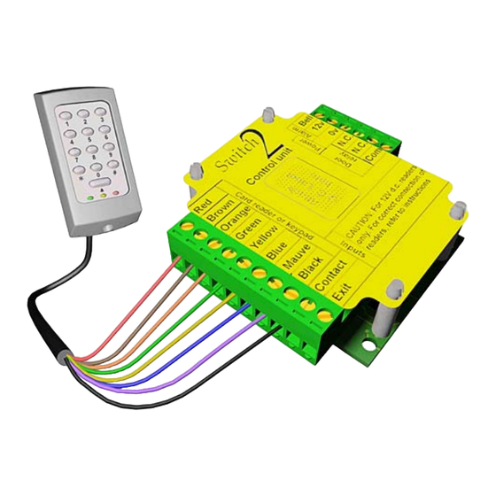
CARDLOCK readers come supplied with 5 metres of cable. The colours of the cable cores correspond directly to the colours on the Switch2 control unit label. When extending the cable distance beyond 5 metres, do not used twisted pair cable as the data signals may become distorted. -
Page 10: Cardlock Readers (12V)
CARDLOCK readers (12v) TOUCHLOCK K series keypads Chapter 3 Wiring... -
Page 11: Proximity P Series Reader
PROXIMITY P series reader PROXIMITY vandal proof reader NOTE: Only Red & Black (Power) and Blue &Yellow (Data) are required. PROXIMITY KP series keypad NOTE: All devices. If two readers or keypads are required they are both be wired to same terminals. Chapter 3 Wiring... -
Page 12: Inputs
Inputs Tamper Switch Brown Orange Green Yellow Blue Mauve Tamper Switch Black Contact Exit If a tamper switch is required, it should be Normally Open – held closed by the cover. It is fitted across Black and Contact and will operate in the same manner as a Door Contact. That is to say an alarm will be generated if the switch opens and no valid access has been granted. -
Page 13: Door Contacts
Door Contacts Brown Orange Normally open door contact (held closed by the door) Green Yellow Blue Mauve Black Contact Exit If door contacts are fitted on a TOUCHLOCK system the bell/alarm output is activated during an alarm (Door Forced) condition and the door bell input on the keypad is disabled. Outputs Bell/Alarm Output ALARM... -
Page 14: Locks
N.O. All Fire systems must be Fail-Safe. Fail secure locks are not permitted. The exit button terminal must NOT used as the Switch2 may not be functional during the emergency. Fire Alarm Relay Under normal conditions, the fire alarm system will provide a constant voltage to the fire alarm relay which will transfer and maintain the 12v supply to the lock. - Page 15 Chapter 3 Wiring...
-
Page 16: Chapter 4 Commissioning
When the system is powered up for the first time the control will bleep 3 times a second. This indicates that Switch2 is waiting to be initialised. The LED will be on, the... -
Page 17: Cardlock & Proximity System
When the system is powered up for the first time the control unit will bleep 3 times a second. This indicates that Switch2 is waiting to be initialised. If a CARDLOCK reader is connected the arrow LED will also be flashing. -
Page 18: Proximity Kp Series Keypad
When installing PROXIMITY KP series keypads, follow exactly the same sequence described previously for TOUCHLOCK systems. Note: If a KP system is enrolled, using the PROXIMITY enrolment card, the Switch2 controller will have to be reset in order to initiate any of the combined PROXIMITY keypad modes. -
Page 19: Chapter 5 Operation
Master code This code is used to enter the programming procedure for the Switch2 control unit. It is set during the initialisation of the unit and can be changed later if necessary. -
Page 20: Default Settings
Remote button An exit/remote button can be connected to Switch2. It can be set-up to work in one of two ways. The button can be programmed to open the door for the door open time. This is set as default. The button can also be programmed to toggle the relay. This second option will change the door condition to the opposite of its current condition every time the button is pressed. - Page 21 Chapter 5 Operation...
-
Page 22: Cardlock & Proximity
When the system is powered up for the first time the control unit will bleep 3 times a second. This indicates that Switch2 is waiting to be initialised. If a CARDLOCK reader is connected the arrow LED will also be flashing. -
Page 23: Using Function Cards - Starter Pack
Swipe the card again after the desired interval (all the LEDs come back on) Silent Operation card This card is used to toggle the beeping of the Switch2 control unit on and off. By default the Switch2 control unit beeps when a user card is swiped. If necessary this beep can be silenced by swiping the silent operation card through the reader. -
Page 24: Default Settings
To re-enrol individual users back on the system see – Enrolment card. Relay Toggle card This card should be used if the output from the Switch2 control unit needs to be a toggle output. Toggle means that instead of the relay opening for a set time and then closing, the relay will stay open until a user card is swiped through the reader to close it again. -
Page 25: Proximity Kp Keypad
PROXIMITY KP keypad Card plus PIN mode If Card plus PIN mode is required the KP reader must first be initialised as a TOUCHLOCK keypad. Once this is done Card plus PIN mode can be entered using the programming menu, menu option 1 (see programming chart). Once in Card plus PIN mode the PROXIMITY card pack can be enrolled, this is done in the same way as for a PROXIMITY system, by presenting the PROXIMITY enrolment card. -
Page 26: Chapter 6 Fault-Finding
Have a copy of the instructions ready to hand • Have the Switch2 control unit serial number to hand • Have appropriate tools ready to use. Reset procedure To set the Switch2 control unit back to its factory settings: • Disconnect the power • Disconnect the GREEN... -
Page 27: Chapter 7 Appendix
The output terminals COM, N.O. and N.C. are voltage free. This means that they can be used to control power using the same supply that drives the Switch2 or may be included as part of an independent circuit to signal other electrical devices e.g. Car Park Barrier. -
Page 28: Chapter 8 Specifications
Chapter 8 Specifications CARDLOCK and PROXIMITY Maximum number of users ......... 10,000 (3,000 in card plus PIN mode) User tokens............... Passive cards and keyfobs Colour access zones ............... Up to 3 (Note 1) Individual access rights................All Users Number of time zones................2 (Note 2) Bar all users ..................... - Page 29 System Exit button ....................... yes Sounder connection................yes (Note 5) Door forced alarm ..................... yes Door relock on closing ................yes (Note 6) Silent Operation....................yes Door Open time ................1 to 60 seconds Card plus PIN (Personal identification number) ..........yes (Note 7) Fail open locks ....................
Need help?
Do you have a question about the Switch2 and is the answer not in the manual?
Questions and answers