Table of Contents
Advertisement
Quick Links
Advertisement
Table of Contents

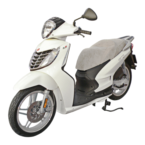
Related Manuals for Malaguti CENTRO SO 4T


Summary of Contents for Malaguti CENTRO SO 4T
- Page 2 50 cc - 4 T FOREWORD • This manual specifically addresses to specialised technical personnel (MALAGUTI authorised service centres and single motor mechanics) and contains all the service interventions indicated by the Manufacturer until the publishing of this document. • Some basic technical information has been intentionally omitted as it is considered to be common knowledge.
- Page 3 50 cc - 4 T NOTES FOR EASY CONSULTATION ABBREVIATIONS TECHNICAL DICTIONARY Torque wrench setting = (DC) Direct current (battery supply) ~ (AC) Alternating current (flywheel supply) Right : Ampere Unit of measurement of the electrical current Picture : Watt Unit of measurement of the electrical power (product of Volts and Amperes;...
- Page 4 50 cc - 4 T SYMBOL LIST CAUTION! IDLING ENGINE Recommendations and SAFETY GLOVES DISASSEMBLY Switch on the engine, at precautions regarding rider These operations require OPERATIONS idling speed, to perfom safety and motor vehicle the use of safety gloves these interventions.
- Page 5 50 cc - 4 T GENERAL WORK PROCEDURES • The recommendations given hereafter are aimed at ensuring maximum work safety as well as at considerably reducing the risk of accidents, personal injury, equipment damage and idle times, and should therefore be strictly adhered to. •...
- Page 6 50 cc - 4 T • Before carrying out any operation, wait for all parts to cool down. • For operations requiring two mechanics, make sure that the various steps to be performed by each of them are clearly defined and co-ordinated beforehand. •...
-
Page 7: Table Of Contents
50 cc - 4 T CONTENTS 1 2 3 4 1 2 3 4 1 2 3 4 DESCRIPTION DESCRIPTION 1 2 3 4 1 2 3 4 1 2 3 4 TECHNICAL DATA ACCESS (after removing the front cover) 1 2 3 4 1 2 3 4 IDENTIFICATION INFORMATION: FRAME N°/ ENGINE N°... - Page 8 50 cc - 4 T Starting system ............electrical and/or kickstarter SPECIFICATIONS lubrication system ................wet sump SPARK PLUG Type ................NGK CR8E - NGK CR8EB TRANSMISSION Primary drive: automatic transmission by V-belt speed change gear Final: by gears. Automatic centrifugal dry clutch. FUEL SYSTEM Carburettor KEIHIN CVK Automatic starter...
- Page 9 50 cc - 4 T ANTI-TAMPERING PLATE IDENTIFICATION DATA: FRAME N° / ENGINE N° • An anti-tampering plate, bearing all vehicle identification data required by Directive • The vehicle’s identification number (VIN) (A) is located on the rear side of the chas- 97/24/CE, is fitted inside the helmet compartment.
- Page 10 50 cc - 4 T Minimum tread depth (front and rear) is 2 mm (F. 6). TYRES Type: Tubeless (wiithout inner tube) F. 6 F. 5 It is possible to use tyres with load and speed indexes that are higher than or identical to those indicated.
- Page 11 NOTE - Maintenance operations should be performed more frequently if the vehicle is used in rainy weather, in dusty places or on rough : coupon terrain. : check : clean Due to their simplicity, checks with no asterisk CAN also be carried out by technicians not authorised by MALAGUTI, but under : adjust their direct responsibility. : replace 07/08...
- Page 12 50 cc - 4 T LUBRICANT TABLE NOTE - Use only recommended products. LUBRICANTS ENGINE OIL (4 STROKE) FORMULA EXCEL SAE 5W40 ENGINE TRANSMISSION OIL T35 - 80W AIR FILTER LUBRICANT AIR FILTER OIL RADIATOR FLUID TOP FLUID BRAKE CIRCUIT FLUID BRAKE FLUID DOT 4 FORK ROD OIL FORK OIL...
- Page 13 50 cc - 4 T FUEL TANK • The fuel tank cap (A) is accessible by raising the seat, using the ignition key (B) and turning it clockwise. Use unleaded gas. ENGINE OIL CHECK LEVEL every 3.000 km • The engine must be cold and the vehicle on level ground. •...
- Page 14 50 cc - 4 T CHANGE TRANSMISSION OIL • After the first 1,000 Km • Every 12,000 Km • Cold engine CHECK LEVEL/ TOP UP • Vehicle on level ground • Place a drip pan under the engine. • Cold engine •...
- Page 15 50 cc - 4 T BLEED BRAKE SYSTEM FRONT CALIPER NOTE - Position the vehicle in a stabile manner and perfectly on level ground. • Remove the oil pump reservoir cover (A), unscrewing the relative screws (V2), in order to be able to top off the fluid.
- Page 16 50 cc - 4 T CHECKING THE REAR BRAKE • Make sure that the idle stroke of the lever is ~ 10 mm. • Ad just the lever by means of the adjuster (A), if necessary. F. 16 F. 17 FORK CHECK OIL LEVEL IN THE CHANGE FORK OIL...
- Page 17 50 cc - 4 T INSTRUMENT BOARD Analogue instruments, Speedometer Current speed in kmh or mph. Odometer Total distance travelled in kmh. Green turn indicator light Blue high beam indicator light Fuel level indicator Orange zone: approaching reserve. Red zone: reserve - Refuel!! Battery level indicator This indicates the charge level of the battery and correct operation of the recharging system.
- Page 18 50 cc - 4 T KEY SWITCH STARTING THE ENGINE Before pushing the starter button to start the motor, first pull the front or rear brake lever and keep Ignition inhibited (extractable key) it pulled. Do not start the engine in a closed ambient, because the exhaust is highly toxic. Preset starting position (non extractable key) To not damage the injection system, never operate the "START"...
- Page 19 50 cc - 4 T LIGHTS HEADLIGHT The headlights are quartz lamps (halogen). • High/Low beam lights (A). Halogen Bulb 12V - 60/55W (H4). • Tail lights (B). Bulb 12V - 5W (W5W). Change light bulb • To reach the headlight bulbs it is necessary to remove the front handle cover (see page 26).
- Page 20 50 cc - 4 T REAR LIGHT UNIT Light bulb replacement • Tail lights (P) • Unscrew the screws (V2). Light bulb 12V - 5W (W5W). • Brake lights (S) Light bulb 12V - 10W (R10W). • Turn signals (E) 12V-10W F.
- Page 21 50 cc - 4 T • Disconnect the connector Tail light (C). • Take out the lamp holder from inside the headlight. • Remove the parabolic spring • Replace the light bulb. carefully. • Reposition the rubber lamp holder (pressure) and remount the cover. Stop light and turn signal light •...
- Page 22 50 cc - 4 T FUSES The electric wiring includes three fuses that are located in the front case and protect the main components from any malfunctions. FUSE REPLACEMENT Open the case and take out the fuse and replace it with one having equal capacity. Spare fuses are located inside the compartment (S).
- Page 23 50 cc - 4 T BATTERY (12V - 9Ah) The battery compartment is located in the front section of the vehicle. FITTING BATTERY (pre-delivery operation) To fit battery, proceed as follows: • Take a charged battery. • Remove the 10A general protection fuse. •...
- Page 24 50 cc - 4 T CHARGE BATTERY • To carry out this operation, it is advisable to remove the battery from its housing, unless the special electrical outlet (A) is used. • Disconnect cables. • It is a good rule to recharge using amperage that is equal to 1/10 of the power of the battery charger.
- Page 25 50 cc - 4 T SPARK PLUG REPLACEMENT every 6,000 km Remove the spark plug when the engine is cold. Type of spark plug to be used: NGK CR8E - NGK CR8EB • For maintenance, disassemble the central panel under the seat (P), remove the three fastening screws (V) and lift the internal profile (with the help of a screwdriver) that is held on two lugs in the foot rest board, carefully extract the hood (C ), with small clockwise and anti clockwise movements;...
- Page 26 50 cc - 4 T PROCEDURES FOR DISMANTLING AND REAR VIEW MIRROR (Right) REMOVING COMPONENTS (optional) REASSEMBLY NOTE • First remove the protection cap (B). REAR VIEW MIRROR (Left) • Uncover and loosen the nut (D). • Unscrew the window holder arm, by F.
- Page 27 50 cc - 4 T FRONT HANDLEBAR COVER • V4. • V. 1 ± 10% 1 ± 10% F. 46 F. 47 • To clear the front handlebar • Free and partially extract the cover, push the area handlebar unit, carefully, as indicated in the figure (on to not damage the paint of both sides), paying...
- Page 28 50 cc - 4 T • Disconnect the • Extract the taillights lamp lamp holder (A) holder (B). • Remove the front handlebar cover. F. 50 F. 51 FRONT • W. COVER • V4. 1 ± 10% 1 ± 10% F.
-
Page 29: Access (After Removing The Front Cover)
50 cc - 4 T ACCESS SEAT (after removing the front cover) • D2. A) Antitheft preset connector B) Key switch connector C) Battery case cover (pag. 22) 3 ± 20% F. 54 F. 55 HELMET • V. COMPARTMENT • V4. •... -
Page 30: Seat Blocking Device
50 cc - 4 T • Partially lift the helmet SEAT BLOCKING DEVICE compartment, as it is constrained by the seat • D2. locking device cable. 3 ± 20% F. 58 F. 59 • Remove the locking/opening unit, complete with the transmission cable. -
Page 31: Access (After Removing The Helmet Compartment)
50 cc - 4 T ACCESS (after removing the helmet compartment) A - Fuel tank B - Fuel level gauge C - Fuel gauge connector F. 61 1) Throttle cable 2) Electric starter, carburator 3) Carburator valve cover 4) Vacuum pipe and fuel valve. 5) Oil fumes expansion pipe F. - Page 32 50 cc - 4 T FUEL LEVEL SENSOR • During operations, screw the tank cap on the union (A), to avoid that any foreign matter falls inside. • Remove the adhesive tape (B), release the sheaths (F) and disconnect the inside connector. •...
-
Page 33: Central Bar
50 cc - 4 T CENTRAL ACCESS • Spark plugs pipette (1). • V3 • Lift carefully the lower part (using a screwdriver), that is secured to the footbar by means of two coupling teeth. F. 67 F. 68 2) Voltage regulator •... -
Page 34: Side Struts
50 cc - 4 T • W. SIDE STRUTS • V3. • V2. F. 71 F. 72 • Remove the side pins and PASSANGER the front coupling element LEVERS (A). • Undo the upper screw (V), holding the self-locking nut underneath. -
Page 35: Footbar
50 cc - 4 T • Unscrew the screws (V), FOOTBAR remove the pillion staff and recuperate the underlying • V4. spring (M). • W4. Clean and grease the fulcrum pin (P). 5 ± 10% F. 75 F. 76 • Release the footbar from the rear fairing with care, paying attention not to lose the four fasteners (A). -
Page 36: Rear Fairing
50 cc - 4 T Do not forget to fit REAR FAIRING the bushings (B) opposite of the screws (V2). REAR HANDLE • V - After removing the closing cap. • V2. 43 ± 15% • Remove the rear handle including the opening/ F. -
Page 37: Full Rear Fairing
50 cc - 4 T • V2A. • Carefully take out the rear light unit. • Disconnect the wires. F. 82 F. 83 FULL REAR FAIRING • V4. 5 ± 10% F. 84 07/08... - Page 38 50 cc - 4 T • V. • Remove the rear fairing with care. • Put the fairing in a safe place, away from 5 ± 10% accidental crashes and heat sources. F. 86 F. 85 ACCESS RIGHT SIDE LEFT SIDE 1) Electric starter 2) Fuel sensor connector resistance connector.
-
Page 39: Rear Fairing Breakdown
50 cc - 4 T REAR FAIRING BREAKDOWN FRONT PART REAR PART • V3. • V3. • Pay attention not to damage to the coupling system (A). F. 89 F. 90 07/08... -
Page 40: Legshield
50 cc - 4 T LEGSHIELD • V2. • Extract the cover (B) of the • Bag holder hook (A). key switch. • V4 5 ± 10% F. 91 2 ± 10% • V. F. 92 • W • Open (carefully) the leg shield, on the left side. -
Page 41: Access (After The Legshield Is Removed)
50 cc - 4 T • Remove the leg-fender. NOTE - After removing the leg-fender, pay attention not to lose the fasteners (A). F. 96 F. 95 ACCESS (after the legshield is removed) 1) Front turn signals 2) Key switch 3) Horn 4) Handlebar fixing nuts 5) Steering wheel regulator ferrules... -
Page 42: Keyswitch
50 cc - 4 T KEY SWITCH HORN • Disconnect the "faston" (A). • Disconnect the connector from the wiring. • V - • Unscrew the tamperproof screws (V2). 10 ± 15% 7 ± 10% F. 98 F. 99 FRONT MUDGUARD •... -
Page 43: Front Wheel
50 cc - 4 T • V. • Remove the front mudguard. • Spacer (A). • V3. 3 ± 10% F. 102 FRONT WHEEL F. 103 • Unscrew the nut (D), holding the wheel pin with a wrench. • Remove the wheel pin (P). •... -
Page 44: Sequence Of Front Wheel Reassembly
50 cc - 4 T SEQUENCE OF FRONT WHEEL REASSEMBLY • Spacer (A) • Odometer transmission (B) • Washer (R ) • Wheel pin (P) • Spacer (C) • Shim (A1) • Wheel pin (D) 53 ± 10% FRONT BRAKE CALIPER •... -
Page 45: Front Shield
50 cc - 4 T HANDLEBAR FRONT SHIELD • Release the leg-fender • Front handlebar. (P. 39). • Rear handlebar (M). • Disconnect the accelerator • Remove the front transmission (A). mudguard (P. 41). • Disconnect the dashboard • Remove the front connectors. - Page 46 50 cc - 4 T FORK FORK LEG • Loosen (V) NOTE - When removing the fork leg, as well as the full fork, the following should • Raise the fork leg a few be removed beforehand: millimetres (A). - Front wheel (page 42) •...
-
Page 47: Muffler
50 cc - 4 T • Undo the two screws (W) MUFFLER and remove the gasket (G). Before operating on • Remove the muffler. the muffler and the exhaust pipe, ensure that the components are cool. 8 ± 15% • V2. 30 ±... - Page 48 50 cc - 4 T REAR MUDGUARD Right side Left side • V. • V1. • Vs. F. 119 F. 120 INTAKE • Release the clamp (A) and remove the exhaust unit. • Refer to the picture to reach the air filter (B). SYSTEM •...
-
Page 49: Shock Absorber
50 cc - 4 T SHOCK REMOUNTING THE ABSORBER SHOCK ABSORBER • First fit the upper screw (Vs) with the Support the central washers and the nut (Ds). part of the frame. • Then the lower screw (Vi), with the washers and the lower nut (Di). - Page 50 50 cc - 4 T • Disconnect the flywheel • Disconnect the cables connector (A). (B - C) of the starter motor. F. 125 • Release the hose (D) by undoing the clamp (E). • Release the camping spring (F). •...
- Page 51 50 cc - 4 T • Cut the clamp and remove • Disconnect the spark plug the connector protection (C). sheaths (A). • Disconnect the electric starter connector (A). F. 129 F. 130 • Unscreew the nut (D). • Disconnect the rear brake 45 ±...
-
Page 52: Frame Size Check
50 cc - 4 T • Slide off the pin (P). Raise the rear part of the motorcycle before sliding off the engine pin. It is advisa- ble to have a second operator available to help carry out this operation. Remember to fit the washer. - Page 53 50 cc - 4 T CABLE POSITIONING, "PIPE SYSTEM" AND ANCHORING TIES. F. 135 F. 137 F. 138 F. 136 07/08...
- Page 54 50 cc - 4 T F. 139 F. 140 07/08...
- Page 55 50 cc - 4 T F. 141 F. 142 07/08...
- Page 56 50 cc - 4 T F. 143 07/08...
- Page 57 50 cc - 4 T F. 144 F. 145 07/08...
- Page 58 50 cc - 4 T F. 146 07/08...
- Page 59 50 cc - 4 T F. 147 F. 148 07/08...
- Page 60 50 cc - 4 T F. 149 F. 150 07/08...
- Page 61 50 cc - 4 T F. 151 F. 152 07/08...
- Page 62 50 cc - 4 T F. 153 07/08...
Need help?
Do you have a question about the CENTRO SO 4T and is the answer not in the manual?
Questions and answers