Sign In
Upload
Manuals
Brands
ABB Manuals
Controller
AC500-S
ABB AC500-S Manuals
Manuals and User Guides for ABB AC500-S. We have
5
ABB AC500-S manuals available for free PDF download: Safety User Manual, System Manual, Operation Manual, Application Note
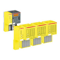
ABB AC500-S Safety User Manual (452 pages)
Safety Programmable Logic Controllers system
Brand:
ABB
| Category:
Controller
| Size: 51.28 MB
Table of Contents
Table of Contents
3
1 Introduction
7
Purpose
7
Document History
8
Validity
10
Important User Information
10
Definitions, Expressions, Abbreviations
11
Functional Safety Certification
13
References/Related Documents
14
2 Overview of AC500-S Safety PLC
15
Overview
15
System
16
Safety Components
17
Intended Use
19
Safety Loop
20
Safety Values
20
Qualified Personnel
21
Lifecycle
21
Installation of Safety Modules
21
Exchange of Modules
22
AC500-S Restart Behaviour
22
Replacing AC500-S Safety PLC Components
22
Environmentally Friendly Disposal
22
Safe Communication
23
Safety Function and Fault Reaction
24
Safety CPU (SM560-S)
24
Safety Module with Safety Input Channels (DI581-S, DX581-S and AI581-S)
25
Safety Module with Safety Output Channels (DX581-S)
25
Safety Function Test
25
Troubleshooting
26
3 AC500-S Safety Modules
32
SM560-S Safety CPU
32
Purpose
32
Functionality
32
Mounting, Dimensions and Electrical Connection
37
Diagnosis and LED Status Display
40
SM560-S Module States
46
SM560-S and Pm5Xx Interaction
51
Technical Data
53
Ordering Data
58
Generic Safety I/O Module Behaviour
58
Overview
58
Safety I/O Module States
59
Undervoltage/Overvoltage
70
Diagnosis
71
DI581-S Digital Safety Input Module
74
Purpose
74
Functionality
76
Mounting, Dimensions and Electrical Connection
79
Internal Data Exchange
84
I/O Configuration
84
Parameterization
85
Circuit Examples
85
LED Status Display
98
Technical Data
98
Ordering Data
105
DX581-S Digital Safety Input/Output Module
106
Purpose
106
Functionality
108
Mounting, Dimensions and Electrical Connection
112
Internal Data Exchange
116
I/O Configuration
116
Parameterization
117
Circuit Examples
117
LED Status Display
126
Technical Data
127
Ordering Data
135
AI581-S Analog Safety Input Module
136
Purpose
136
Functionality
138
Mounting, Dimensions and Electrical Connection
139
Internal Data Exchange
143
I/O Configuration
143
Parameterization
144
Circuit Examples
144
LED Status Display
149
Technical Data
149
Ordering Data
157
TU582-S Safety I/O Terminal Unit
158
Functionality
158
Mounting, Dimensions and Electrical Connection
159
Technical Data
162
Ordering Data
164
4 Configuration and Programming
165
Overview
165
Workflow
167
System Configuration and Programming
168
Installation
169
License Activation
169
Creation of New Project and User Management
170
Working with PROFINET / Profisafe F-Devices
174
Instantiation and Configuration of Safety Modules/Definition of Variable Names
177
Programming of AC500-S Safety CPU
191
Checking of Program and System Configuration
209
Codesys Safety Programming Guidelines
210
Overview
210
Framework
210
Language-Specific Programming Guidelines
212
General Programming Guidelines
221
Safety-Oriented and Non-Safety-Oriented Parts of the Application
221
Safety Code Analysis Tool
223
AC500-S Libraries
224
Overview
224
Safety_Standard.lib
226
Safetybase_Profisafe_Ac500_V22_Ext.lib
231
Safetyext_Ac500_V22.Lib
235
DPRAM_SM5XX_SEND and DPRAM_SM5XX_REC in Sysint_Ac500_V10.Lib
259
Safetyblocks_Plcopen_Ac500_V22.Lib
265
5 Safety Times
395
Overview
395
Fault Reaction Time
396
Safety Function Response Time
396
6 Checklists for AC500-S Commissioning
405
Overview
405
Checklist for Creation of Safety Application Program
406
Checklist for Configuration and Wiring
409
Checklist for Operation, Maintenance and Repair
410
Verification Procedure for Safe Iparameter Setting in AC500-S Safety I/Os
412
Verification Procedure Workflow
413
Verification Tables for Iparameter Settings in AC500-S Safety I/Os
417
7 Safety Application Examples
425
Overview
425
Example 1: Diagnostics Concept
426
Functional Description of Safety Functions
426
Graphical Overview of Safety Application Interface
427
Declaration of Used Variables
427
Program Example
428
Additional Notes
428
Example 2: Muting
430
Functional Description of Safety Functions
430
Graphical Overview of the Safety Application Interface
431
Declaration of Used Variables
432
Program Example
434
Additional Notes
435
Example 3: Two-Hand Control
437
Graphical Overview of the Safety Application Interface
438
Program Example
440
8 Index
442
Appendix
445
A System Data for AC500-S-XC
446
Advertisement
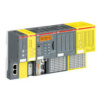
ABB AC500-S Safety User Manual (404 pages)
Brand:
ABB
| Category:
Industrial Equipment
| Size: 25.82 MB
Table of Contents
Table of Contents
2
Introduction
5
Purpose
5
Document History
5
Validity
7
Important User Information
7
Definitions, Expressions, Abbreviations
8
Functional Safety Certification
10
References / Related Documents
11
Applicable Standards
11
Overview of AC500-S Safety PLC
13
Overview
13
System
13
Safety Components
14
Intended Use
16
Safety Loop
17
Safety Values
17
Qualified Personnel
18
Lifecycle
18
Installation of Safety Modules
18
Exchange of Modules
19
AC500-S Restart Behavior
19
Replacing AC500-S Safety PLC Components
19
Environmentally Friendly Disposal
19
Safe Communication
19
Safety Function and Fault Reaction
21
Safety CPU (SM560-S / SM560-S-FD-1 / SM560-S-FD-4)
22
Safety Module with Safety Input Channels (DI581-S, DX581-S and AI581-S)
22
Safety Module with Safety Output Channels (DX581-S)
23
Safety Function Test
23
Troubleshooting
23
FAQ - AC500-S Safety PLC
28
AC500-S Safety Modules
32
Safety CPU - SM560-S / SM560-S-FD-1 / SM560-S-FD-4
32
Purpose
32
Functionality
32
Mounting, Dimensions and Electrical Connection
39
Diagnosis and LED Status Display
41
Safety CPU Module States
43
Safety and Non-Safety CPU Interaction
47
Technical Data
47
Ordering Data
50
Generic Safety I/O Module Behavior
50
Overview
50
Safety I/O Module States
50
Undervoltage / Overvoltage
59
Diagnosis
60
DI581-S Safety Digital Input Module
61
Purpose
61
Functionality
62
Mounting, Dimensions and Electrical Connection
65
Internal Data Exchange
69
I/O Configuration
69
Parameterization
69
Circuit Examples
69
LED Status Display
81
Technical Data
82
Ordering Data
85
DX581-S Safety Digital Input/Output Module
86
Purpose
86
Functionality
87
Mounting, Dimensions and Electrical Connection
91
Internal Data Exchange
95
I/O Configuration
95
Parameterization
95
Circuit Examples
96
LED Status Display
101
Technical Data
102
Ordering Data
106
AI581-S Safety Analog Input Module
107
Purpose
107
Functionality
108
Mounting, Dimensions and Electrical Connection
110
Internal Data Exchange
113
I/O Configuration
113
Parameterization
113
Circuit Examples
114
LED Status Display
118
Technical Data
119
Ordering Data
122
TU582-S Safety I/O Terminal Unit
123
Functionality
123
Mounting, Dimensions and Electrical Connection
124
Technical Data
126
Ordering Data
127
Configuration and Programming
128
Overview
128
Workflow
129
System Configuration and Programming
130
Installation
130
License Activation
130
Creation of New Project and User Management
130
Working with Profinet/Profisafe F-Devices
131
Instantiation and Configuration of Safety Modules / Definition of Variable Names
133
Programming of AC500-S Safety CPU
141
Checking of Program and System Configuration
159
CODESYS Safety Programming Guidelines
172
Overview
172
Framework
172
Language-Specific Programming Guidelines
174
General Programming Guidelines
180
Safety and Non-Safety Parts of the Application
181
Safety Code Analysis Tool
181
AC500-S Libraries
182
Overview
182
Safety_Standard.lib
183
Safetybase_Profisafe_Lv200_Ac500_V22.Lib
187
Safetyblocks_Plcopen_Ac500_V22.Lib
191
Safetydeviceext_Lv100_Profisafe_Ac500_V27.Lib
294
Safetyext2_Lv100_Ac500_V27.Lib
298
Safetyext_Ac500_V22.Lib
300
Safety Times
317
Overview
317
Fault Reaction Time
317
Safety Function Response Time
317
Checklists for AC500-S Commissioning
326
Overview
326
Checklist for Creation of Safety Application Program
326
Checklist for Configuration and Wiring
328
Checklist for Operation, Maintenance and Repair
330
Verification Procedure for Safe Iparameter Setting in AC500-S Safety I/Os
332
Verification Procedure Workflow
333
Verification Tables for Iparameter Settings in AC500-S Safety I/Os
334
Safety Application Examples
342
Overview
342
Example 1: Diagnostics Concept
343
Functional Description of Safety Functions
343
Graphical Overview of Safety Application Interface
344
Declaration of Used Variables
344
Program Example
345
Additional Notes
345
Example 2: Muting
346
Functional Description of Safety Functions
347
Graphical Overview of the Safety Application Interface
348
Declaration of Used Variables
348
Program Example
350
Additional Notes
351
Example 3: Two-Hand Control
352
Functional Description of Safety Functions
352
Graphical Overview of the Safety Application Interface
353
Declaration of Used Variables
353
Program Example
354
Additional Notes
354
Index
356
Appendix
359
A System Data for AC500-S-XC
360
B Usage of Safety CPU with V2 Non-Safety CPU Pm5Xx
366
C Usage of Safety CPU with V3 Non-Safety CPU Pm56Xx
384
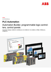
ABB AC500-S System Manual (119 pages)
Automation Builder, programmable logic controllers, control panels
Brand:
ABB
| Category:
Industrial Equipment
| Size: 3.43 MB
Table of Contents
Table of Contents
2
Preface
4
Guidance through the Documentations
4
Do I Have AC500 V2 or AC500 V3
4
Regulations
5
Older Revisions of this Document
5
Use the "Magic Button" to Display Your Current Position in the Table of Contents
6
Structure of Safety Notices
6
Safety Instructions
8
System Overview
12
AC500 PLC Product Family
12
AC500/S500 System Structure
13
AC500-Eco/S500-Eco System Structure
14
AC500/S500: Short Description Hardware
16
AC500-Eco/S500-Eco: Short Description Hardware
20
Ac500-S
21
CP600 Control Panels
22
Automation Builder: Short Description Engineering Software
22
Application Planning
24
Processor Module and I/O Selection
24
Communication Within the PLC
24
Power Supply Dimensioning
26
Calculation of the Total Current Consumption
26
Dimensioning of the Fuses
28
Libraries and Software
29
Mechanical Planning and Installation
30
Control Cabinet Assembly for AC500 (Standard)
30
Control Cabinet Assembly for AC500-Eco
32
Mounting and Demounting - General Information
33
Optimized Mounting of the Option Boards
34
Mounting and Demounting the Terminal Base
35
Mounting and Demounting the AC500 Processor Module
37
Mounting and Demounting the Terminal Unit
38
Mounting and Demounting the Communication Module
39
Mounting and Demounting the I/O Module
41
Mounting and Demounting the AC500-Eco Processor Module
42
Mounting a Processor Module on a DIN Rail
42
Demounting a Processor Module Mounted on a DIN Rail
43
Mounting a Processor Module on a Metal Plate
44
Demounting a Processor Module Mounted on a Metal Plate
45
Mounting of TA5301-CFA
46
Mounting and Demounting the S500-Eco I/O Module
46
Accessories for AC500 (Standard)
50
Inserting and Removing a Memory Card
51
Accessories for AC500-Eco
52
Mounting and Demounting the Option Boards
52
Mounting and Demounting of the Terminal Blocks for Onboard I/Os
54
Inserting and Removing a Memory Card
56
Control Panels CP600
57
Wiring
58
Grounding Concept
58
EMC-Conforming Assembly and Construction
59
General Principles
59
Cable Routing
60
Cable Shields
61
Control Cabinet
61
Reference Potential
62
Equipotential Bonding
62
Connection and Wiring
63
Ac500
64
AC500-Eco
71
Control Panels CP600
72
Configuration and Programming
73
Cyber Security
74
Defense in Depth
75
Secure Operation
76
Hardening
79
Certificates Factory Default - no Encryption
80
Open Ports and Services
83
Commissioning
84
Operation
86
Status Leds, Display and Control Elements
86
PLC Firmware/Application Update
86
Control Panel Firmware/Application Update
87
Reset to Factory Settings
87
Troubleshooting
88
Maintenance
90
Replace an AC500 Module
90
Replace an I/O Module with Hot Swap
91
Preconditions for Using Hot Swap
91
Compatibility of Hot Swap
94
Hot Swap Behavior
95
Decommissioning
96
Recycling
97
Appendix
98
Diagnosis Messages Via Display of the Processor Module
98
Error Severity E2: Severe Errors
99
Error Severity E3: Minor Errors
100
Error Severity E4: Warnings
104
Error Severity E11: Parameter Errors
106
Diagnosis Messages of Communication Modules or Fieldbuses
108
PLC Firmware/Application Update Via Memory Card
108
Preparation of Memory Card
108
Execution of Update Via Memory Card
111
Glossary
113
Index
116
Advertisement
ABB AC500-S Operation Manual (31 pages)
training case
Brand:
ABB
| Category:
Industrial Equipment
| Size: 1.09 MB
Table of Contents
Table of Contents
2
Disclaimer
3
Introduction
4
Before You Start
5
Safety Notices
5
Markups
5
Definitions, Expressions, Abbreviations
6
References / Related Documents
6
Product Overview
7
Product Identification
8
Environmental Conditions
8
Deliverables
9
Ac500-S
9
Ac500/S500
10
Accessories
10
Dimensions
11
Getting Started
12
How to Remove TA514-SAFETY from the Case
13
Power Supply
13
Functionality - Front Panel
15
Circuit Diagrams
18
Environmentally Friendly Disposal
19
Attachment
20
ABB AC500-S Application Note (24 pages)
Safety Programmable Logic Controllers
Brand:
ABB
| Category:
Controller
| Size: 1.45 MB
Table of Contents
Table of Contents
2
1 Introduction
3
Purpose
3
Document History
4
Validity
4
Important User Information
4
Definitions, Expressions, Abbreviations
4
References / Related Documents
5
2 Usage of Digital Standard I/Os in Functional Safety Applications up to PL C
6
Overview
6
Task
8
Solution
8
3 Example
14
General
14
Safety Function
14
Functional Description
15
Design Features
16
Implementation Details
16
Common Cause Failures
18
Systematic Failures
19
Safety Function Response Time
20
Calculation of the Probability of Failure and Correspondence to PL (ISO 13849-1)
20
4 Conclusion
23
Advertisement
Related Products
ABB AC500-eCo Series
ABB AC500-eCo Starter-Kit
ABB ACS150 series
ABB ACS800-37-0120-5
ABB ACS800-37-2200-5
ABB ACS800-37-0790-7
ABB ACS55-01E-01A4-2
ABB ACS580-07-0640A-4
ABB ACH550-UH-059A-2
ABB ACB530-PC-486A-4
ABB Categories
Industrial Equipment
Controller
Measuring Instruments
Battery Charger
DC Drives
More ABB Manuals
Login
Sign In
OR
Sign in with Facebook
Sign in with Google
Upload manual
Upload from disk
Upload from URL