
Related Manuals for Leica RM2255


Summary of Contents for Leica RM2255
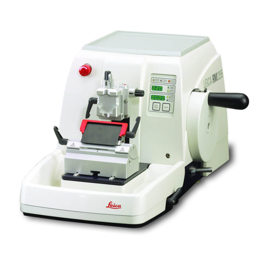
- Page 1 Leica RM2255 Rotary Microtome Instruction Manual Leica RM 2255 V1.4 English - 02/2007 Always keep this manual with the instrument. Read carefully before working with the instrument.
- Page 3 Leica reserves the right to change technical stand it following thorough investigation in this specifications as well as manufacturing field.
-
Page 4: Table Of Contents
Table of contents 1. Important notes ..........................6 Symbols in the text and their meanings ..................6 Qualification of personnel ......................... 6 Intended use of instrument ....................... 6 Instrument type ........................... 6 2. Safety ..............................7 Safety notes ............................7 Warnings .............................. - Page 5 Cleaning the instrument ........................67 Maintenance ............................. 69 8.2.1 Replacing fuses ..........................69 8.2.2 Maintenance instructions ....................... 70 8.2.3 Lubricating the instrument ......................71 9. Warranty and service ........................72 10.EC Declaration of Conformity ...................... 73 People's Republik of China ........................Leica RM2255...
-
Page 6: Important Notes
Important notes 1.1 Symbols in the text and their meanings 1.3 Intended use of instrument The Leica RM2255 is a fully automatic, motor- Dangers, warnings and cautions ized rotation microtome with a separate control appear in a gray box and are marked... -
Page 7: Safety
The protective devices on both instrument and accessories may neither be removed nor modified. Only service personnel qualified by Leica may repair the instrument and access the instrument’s internal components. 2.2 Warnings The safety devices installed in this instrument by the manufacturer only constitute the basis for accident prevention. - Page 8 2. Safety Warnings – Safety instructions / warning labels attached to the instrument • Safety instruction labels on the instrument marked with a warning triangle indicate that the correct operating instructions (as described in this manual) must be followed when operating or replacing the instrument component bearing the label.
- Page 9 • When using detergents please comply with the safety precautions of the manufacturer. • Turn the instrument off with the mains switch and pull the mains plug, before replacing the fuses! Only use fuses of the same specification! For fuse specifications, refer to chapter 3.3 – "Technical data". Leica RM2255...
-
Page 10: Integrated Safety Devices
Safety 2.3 Integrated safety devices Emergency-stop function The emergency-stop function is activated with the red EMERGENCY STOP switch (1) on the upper left of the front of the microtome. The sectioning motor stops immediately when the EMERGENCY STOP switch is pressed. The red LED in the E-STOP field (2) on the control panel of the in- strument lights up, indicating that the emergency stop func- tion has been activated. - Page 11 For the new knife holder E, the two clamping levers (10, 11) must always remain in the position shown. Clamping lever for the blade (10) at the right, clamping lever for the lateral displacement (11) at the left. Fig. 6 Leica RM2255...
-
Page 12: Instrument Components And Specifications
Instrument components and specifications 3.1 Overview – instrument components Leica RM2255 Tray Universal Control panel on cassette clamp the instrument Clamping lever for Handwheel lateral displacement locking mechanism Smooth-turning handwheel Knife holder E with lateral displacement Lever for activating the... -
Page 13: Instrument Specifications
Connecting jack connection for foot switch Fig. 8 3.2 Instrument specifications The Leica RM2255 is a motorized rotary • The specimen retraction can be turned off. microtome. In manual operation the retraction can be adjusted. In motorized operation the • The specimen feed system with zero-back-... -
Page 14: Technical Data
Instrument components and specifications 3.3 Technical data General Approvals: The instrument-specific marks are located next to the identification label. Nominal supply voltages: 100 / 120 / 230 / 240 V AC ±10% Nominal frequency: 50/60 Hz Power draw: 340 VA ➀... - Page 15 120 - 420 mm/s ± 10% Repositioning of knife holder base north-south: ± 24 mm east-west: ± 23 mm Maximum specimen size (W x H x D): 50 x 60 x 40 mm Specimen orientation horizontal: 8° vertical: 8° Leica RM2255...
-
Page 16: Startup
The accessories are included at the top of the package (item Fig. Check the delivery carefully against the packing list, delivery note and your order. Should there be any discrepancy, please contact the Leica selling unit handling your order. Instruction manual V 1.4 – 02/2007... -
Page 17: Unpacking And Installation
• To move the instrument, hold it by the front of the base plate, lift it up gently and slide it on its slides. Fig. 9 Leica RM2255... -
Page 18: Assembling The Handwheel
(outlets) of the country of use. Do not use an extension cable without a ground wire! Checking the voltage Before connecting the instrument to The Leica RM2255 can be connected to various the power supply, be absolutely electrical power grids (depending on voltage certain to check that the voltage... - Page 19 After transporting, please wait at least 2 hours to allow the instrument to adopt the ambient temperature before turning it on! Failure to comply with this may cause damage to the instrument. Leica RM2255...
- Page 20 Startup Connecting the dummy plug • Insert the dummy plug provided (18) into the connecting jack (19) on the rear of the in- strument and fasten it by tightening the screws (20). Connecting the foot switch (optional accessory) • If a foot switch is to be used with the instru- ment, attach it in the same way as the dummy plug.
-
Page 21: Switching On The Instrument
If the yellow LED in the M-STOP field (4) of the control panel is lit, the me- chanical handwheel lock or the handwheel brake (Item 3 in Fig. 3) is activated. The instrument cannot be started as long as the LED is lit. Leica RM2255... -
Page 22: Operation
Operation 5.1 Operating elements and their functions The operating functions of the microtome are divided between a control panel and a display unit on the microtome. A control panel on the instrument displays the current operating mode as well as various settings. -
Page 23: Control Panel
Coarse feed Coarse feed Coarse feed Coarse feed Start and stop buttons backward forward forward backward for motorized section- fast fast slow slow Sectioning mode: Multiple Multiple Single Single step step step step backward forward forward backward Fig. 15 Leica RM2255... -
Page 24: Display And Control Elements
Operation 5.1.3 Display and control elements Three-digit display This display is located both on the instrument and on the control panel. If the SECT LED is lit up, the display shows the section thickness setting in μm. If the TRIM LED is lit up, the display shows the trimming section thickness setting in μm. - Page 25 The travel continues as long as the button is held depressed. • During the forwards movement, the yellow LED (41) in the button flashes. When the front end position is reached, an acoustic signal is heard and the LED stops flashing and remains lit. Leica RM2255...
- Page 26 Operation Four-digit display on the instrument The four-digit display is adjustable. When the Σ Σ Σ Σ Σ μm LED is lit, the display shows the sum of the section thicknesses in μm for all sec- tions completed since the instrument was switched on.
- Page 27 "OFF". • To exit the retraction settings, press MENU MODE. When retraction is switched off, the specimen is not retracted. The yellow LED (4) of the RETRACT indicator does not light up. Leica RM2255...
- Page 28 5. Operation Setting the sectioning speed • The sectioning speed can be set continuously (in the range of 0 - 420 mm/s) using the rotary knob. The speed selector has a scale graduation from 1 to 10. The graduation is provided for reference purposes and does not indicate a particular speed.
- Page 29 • To stop motorized sectioning, press RUN/STOP or ENABLE. If both the green and the yellow LEDs in the RUN/STOP button are lit up, the cutting motor is still running; however it will stop in the next upper end position of the vertical stroke. Leica RM2255...
- Page 30 5. Operation Motorized sectioning In motorized operation, you can choose between three operating modes: CONT = continuous stroke SINGLE = single stroke STEP = step stroke CONT (continuous stroke) operating mode • Select CONT operating mode. After beginning the sectioning process, sectioning continues until the process is stopped by pressing RUN/STOP or ENABLE.
- Page 31 • You can continue to work on the specimen by moving it back a short distance using the coarse feed buttons (set trimming mode!). • The STEP function is disabled in the remaining feed range. Leica RM2255...
- Page 32 5. Operation Foot switch (optional accessory) The foot switch can be used to control the motorized sectioning process. It also has a function that is similar to the emergency stop function. Caution! In addition to the foot switch, all control panel functions and all buttons on the instrument continue to be active.
- Page 33 (50x55 mm) is used, the speci- • To lock the current orientation, turn the men orientation of 8° in north-south eccentric lever (29) backwards. direction is no longer possible. The usable angle is only about 4° in this case. Leica RM2255...
- Page 34 5. Operation Fine adjustment of the force balance If another accessory of a different weight is mounted on the object head (33), you must check whether it is necessary to readjust the force balance. Checking the correct setting: • Attach the new accessory and clamp the specimen.
-
Page 35: Inserting The Knife Holder
4 (71) until the knife holder (57) can be moved. • Place the knife holder (57) with the under- side groove onto the T-piece (56) of the knife holder base (51). • To clamp, retighten the screw (58). Fig. 24 Leica RM2255... -
Page 36: Inserting The Universal Cassette Clamp
Operation 5.3 Inserting the universal cassette clamp There are two versions of the specimen holder, one with and one without specimen orientation, which are interchangeable. The object orientation allows for simple position correction of the specimen surface when the specimen is clamped into place. You can use the specimen holder fixture (60) to hold all available accessory specimen clamps (for more information, see... -
Page 37: Adjusting The Clearance Angle
The recommended clearance angle setting for knife holder E ranges from 59.1 a minimum of 2.5 ° to 5 °. 59.2 • Hold down the knife holder in this position and retighten the screw (58) for clamping. Fig. 26 Leica RM2255... -
Page 38: Clamping The Specimen
Operation 5.5 Clamping the specimen Always clamp the specimen block BEFORE clamping the knife. Lock the handwheel and cover the knife edge with the knife guard prior to any manipulation of knife or specimen, prior to changing the specimen block and during all work breaks! •... -
Page 39: Trimming The Specimen
• Using the CUT MODE button, select the CONT operating mode (continuous stoke). • Deactivate the handwheel lock and release the brake. • Start motorized sectioning and trim the sample. • Terminate trimming when the desired sectioning surface and depth have been reached. Leica RM2255... -
Page 40: Sectioning
Operation 5.8 Sectioning Always use a different area of the cutting edge for trimming and sectioning. To do so, laterally displace the blade or knife in the knife holder. When using the knife holder E with lateral movement, it is sufficient to move the knife holder sideways. -
Page 41: Optional Accessories
• Finally, place the dovetail holder (2) and fasten driver. by screwing in the 4 screws (1) using an Allen • Completely screw in the setscrews (3+4). key size 3. Leica RM2255... -
Page 42: Fine-Directional Fixture For Specimen Clamps
Optional accessories 6.1.3 Fine-directional fixture for specimen clamps • Before the fine-directional fixture for specimen clamps can be mounted, loosen 4 screws (10) (Allen key size 3) and carefully remove the fixture for specimen clamps from the baseplate (9). • Using the 4 supplied screws (11) and the Allen key size 3, fasten the baseplate to the object head (12). -
Page 43: Quick Clamping System
It is used as specimen holder for use with the fine-directional fixture for specimen clamps with zero point indicators or the directional fix- ture for specimen clamps. • Screw the 4 screws (13) into bore A with an Allen key size 2.5 and tighten them. Fig. 30 Leica RM2255... -
Page 44: Specimen Clamps And Holders
Optional accessories 6.2 Specimen clamps and holders All specimen clamps available as accessories can be integrated into either the directional or non-directional specimen holder fixture. 6.2.1 Standard specimen clamp The standard specimen clamps are available in two sizes: 40 x 40 mm and 50 x 55 mm. They are designed for direct clamping of rect- angular blocks. -
Page 45: Foil Clamp Type 1
(74) by turning the set screw (77) against the fixed jaw (73). • Insert the foil clamp in the standard speci- men clamp as shown. • Turn the knurled screw (66) clockwise to clamp the foil clamp in the standard specimen clamp. Fig. 34 Leica RM2255... -
Page 46: Foil Clamp Type 2
Optional accessories 6.2.4 Foil clamp type 2 The foil clamp type 2 is appropriate for large foil ribbons. It is mounted in the standard specimen clamp. • To open the jaws (78) and (79) lightly loosen the 3 screws ( ) with an Allen key size 4 •... -
Page 47: Universal Cassette Clamp
Universal cassette clamp, ice-cooled Use the ice-cooled UCC with the non- directional specimen holder fixture only! • Ice cubes can be made using the included Paraflex mold (a). • Quick clamping system (b), see page 43. Fig. 37 Leica RM2255... -
Page 48: Holder For Round Specimens
Optional accessories 6.2.6 Holder for round specimens The holder for round specimens is designed to accommodate cylindrical samples. Inserts for specimens of 6, 15 and 25 mm diameter are available. • To mount the required insert (89.1-3) turn the 89.1 clamping ring (90) counterclockwise and remove it. -
Page 49: Super Mega-Cassette Clamp
If the directional fixture for specimen clamps is used with the rigid knife holder base, the orientation must be in position "0" and the cover for backlighting illumination must be detached. (Danger of collision if not observed!) NEVER use the super mega-cassette clamp with backlighting illumination! Leica RM2255... -
Page 50: Knife Holder Base And Knife Holder
Optional accessories 6.3 Knife holder base and knife holder The plastic handles of all clamping levers on the instrument and knife holders can be moved to the position that is most convenient for each user. Pull the grip (94) out of the lever, hold it in this position, and rotate it to the desired position. -
Page 51: Knife Holder E/E-Tc
Prior to inserting the blade, both knife The knife holder E-TC is designed for holder and knife holder base must the Leica TC-65 tungsten carbide have been installed on the instrument! blades. Inserting the blades, knife holder E and E-TC •... - Page 52 Leica Biosystems offers special prices for new clamp mounts in case of damages to the clamp mount after the warranty has expired. In this way, perfect function of the device can be ensured over the course of many years.
- Page 53 The vessel is filled with water up to the blade. After trimming, remove the section waste from the tray and create the sections to be prepared. The sections floating on the surface of the water can be removed using the glass slide. Fig. 46 Leica RM2255...
-
Page 54: Knife Holder N/Nz
Optional accessories 6.3.3 Knife holder N/NZ The knife holders N and NZ are appropriate for standard steel and tungsten carbide knives, profile c and d, up to 16 cm long. The integrated height adjustment feature allows you to also use knives that have been resharpened numerous times. Mounting the knife support bar •... - Page 55 • Push the knife (47) to the left or right as required. • To clamp the knife (47), always tighten the clamping screw (49) first which is located on the side to which the knife has been repositioned by turning it clockwise. Leica RM2255...
-
Page 56: Section Waste Tray
Optional accessories 6.4 Section waste tray • Push the section waste tray (18) from the front to the microtome base plate (53) until it is held in place by the two magnets (39) (on the front of the microtome base plate). To remove the section waste tray, lift it slightly and pull it off towards the back. -
Page 57: Tray
(but for at least six hours) at approx. -23 °C. • Reassemble the freezer plate and insulation jacket and place them on the bench or the Fig. 51 instrument. Leica RM2255... -
Page 58: Universal Microscope Carrier
3 - Horizontal arm with cross-member (d) and support ring (e) 4 - Support plate, large (for RM2235, RM2245 and RM2255) 5 - Support plate, small (for RM2265) 6 - Allen key, size 3 7 - 4 countersunk screws to install support plate 8 - Allen key, size 8 Fig. - Page 59 • Slide the horizontal arm (3), flat side facing the lock screw (g), into the cross-member (d) and tighten. For more information on connecting and using the microscope, magnifying lens or cold-light source, please see the appropriate manual. Fig. 57 Leica RM2255...
-
Page 60: Magnifying Lens
Optional accessories 6.9 Magnifying lens The magnifying lens provides a 2x magnification and can be used with all Leica 2200 series rotary microtomes. • Open the screw (3) on the horizontal arm of the microscope carrier in a counterclock- wise direction. -
Page 61: Cold Light Source
• Switch on the Cold light source using the power switch (7). • Remove the protective caps (8) and align the light guide with the specimen. Fig. 62 Fig. 64, Leica rotary microtome with installed optional Fig. 63 accessories: magnifying lens and fiber-optic light guide Leica RM2255... -
Page 62: Ordering Information
Optional accessories 6.12 Ordering information Fixture for specimen clamps, rigid, silver ........0502 38160 Fixture for specimen clamps, directional, silver ......0502 38949 Fixture for specimen clamps, directional, silver ......0502 37717 Quick clamping system, complete ............ 0502 37718 Knife holder-base rigid, silver ............0502 37962 Knife holder N RM22xx, silver ............ - Page 63 Universal microscope carrier, complete ......... 0502 40580 Magnifying lens assembly ..............0502 42790 Cold light sources Leica CLS 100X, 100-120V/50-60Hz ..........0502 30214 Leica CLS 100X, 230V/50-60Hz ............. 0502 30215 Leica CLS 100X, 240V/50-60Hz ............. 0502 30216 Fiber-optic light guide ................ 0502 30028 Backlighting assembly ...............
-
Page 64: Customized Solutions
Following is a list of the most common problems which can arise while working with the instrument, along with possible causes and troubleshooting procedures. If the malfunction cannot be remedied with any of the options listed in the table, or the problem occurs repeatedly, inform the Leica Service Support immediately. Problem Possible cause Corrective action 1. - Page 65 2. Release both buttons simulta- buttons of the control panel neously. were not released simulta- neously after starting. • HOME and STOP are lit up 1. The end position detection is 1. Contact Leica after-sales simultaneously. defective. service. Leica RM2255...
-
Page 66: Possible Faults
Customized solutions 7.2 Possible faults Problem Possible cause Corrective action 1. Thick/thin sections • Check the clamping positions • Insufficient clamping of blade, and repeat the clamping process knife holder, specimen or orien- The sections alternate between tation. being thick and thin. In extreme cases, there are no sections •... -
Page 67: Cleaning And Maintenance
The instrument must be completely dry before it can be used again. Cleaning the knife Always wipe the knife from the back of the knife to the cutting edge. NEVER wipe in the opposite direction - risk of injury! Clean using an alcohol-based solution or acetone. Leica RM2255... - Page 68 Cleaning and maintenance Knife holder E Take the knife holder apart for cleaning. To do so, proceed as follows: • Fold the knife guard (9) and ejector (84) downward. • Rotate the clamping lever (11) of the lateral dis- placement forwards and pull it out sideways. •...
-
Page 69: Maintenance
• Remove the fuses. While doing so, leave the voltage selector switch block (24) in the housing. • Replace defective fuses and reinstall the voltage selector into the instrument. • Check that the correct voltage value is displayed in the viewing window (22). Fig. 69 Leica RM2255... -
Page 70: Maintenance Instructions
↓ ↓ ↓ ↓ ↓ (switching between trimming and sectioning mode). This is a reminder that the instrument must be inspected by an autho- rized Leica service technician, regardless of how heavily the instru- ment has been used. Instruction manual V 1.4 – 02/2007... -
Page 71: Lubricating The Instrument
• Sliding surfaces of the finger guard (8). • Knurled nuts (73) for measuring height ad- justment. Universal cassette clamp: • Axle of the clamping lever (90) of the cas- sette clamp. After lubrication, move the lever back and forth several times. Fig. 70 Leica RM2255... -
Page 72: Warranty And Service
Leica Biosystems Nussloch GmbH guarantees that the contractual prod- uct delivered has been subjected to a comprehensive quality control pro- cedure based on the Leica in-house testing standards, and that the prod- uct is faultless and complies with all technical specifications and/or agreed characteristics warranted. -
Page 73: Ec Declaration Of Conformity
10. EC Declaration of Conformity EC Declaration of Conformity We herewith declare, in exclusive responsibility, that the Leica RM2235 – Rotary Microtome was developed, designed and manufactured to conform with the • Council Directive 98/37/EEC and • European council Directive 98/79/EG (IVDD). -
Page 74: People's Republik Of China
People's Republik of China Instruction manual V 1.4 – 02/2007...
Need help?
Do you have a question about the RM2255 and is the answer not in the manual?
Questions and answers