
Related Manuals for ABB vital 1


Summary of Contents for ABB vital 1
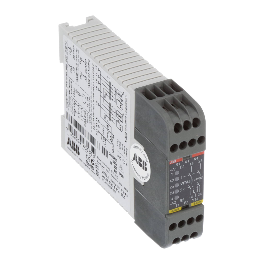
- Page 1 Original instructions Vital 1 Safety module ABB Jokab Safety Varlabergsvägen 11, SE-434 39, Sweden www.abb.com/jokabsafety...
- Page 2 DAMAGES, LOSS OF PROFITS OR COMMERCIAL LOSS IN ANY WAY CONNECTED WITH THE PRODUCTS, WHETHER SUCH CLAIM IS BASED ON CONTRACT, WARRANTY, NEGLIGENCE, OR STRICT LIABILITY. In no event shall responsibility of ABB JOKAB SAFETY for any act exceed the individual price of the product on which liability asserted.
-
Page 3: Table Of Contents
Connection examples ............................... 9 Number of Edens that can be used with Vital 1 ...................... 11 Number of Tina units that can be used with Vital 1 ....................12 Example connections of units and cable lengths to Vital 1 ..................13 Connection advice for dynamic sensors to Vital 1 .................... -
Page 4: Introduction
Introduction Scope The purpose of these instructions is to describe the safety module Vital 1 and to provide the necessary information required for installation and operation. Audience This document is intended for authorized installation personnel. Prerequisites It is assumed that the reader of this document has knowledge of the following: ... -
Page 5: Overview
General description Vital 1 is a safety module that generates and monitors a dynamic safety signal, which makes it possible to achieve a redundant safety system that complies with PL e, category 4 using only a single dynamic safety signal. This allows quick and straightforward installation of the entire safety system. -
Page 6: Function Description
Vital 1 with an even number of sensors connected in series between T1 and R1. S1 connected to B1. Vital 1 with an odd number of sensors connected in series between T1 and R1. S1 disconnected. -
Page 7: Connections
Warning! Connection cables from ABB JOKAB Safety must be used in the safety circuit to ensure that no short circuits of two inverted or non-inverted signals are possible within the connection cables. If other cables are used, the installer must ensure that such short-circuits are not possible. -
Page 8: Reset Connections
Vital 1 has not been reset (RES). NB: If the safety light beam Spot 10/35 is connected to Vital 1, the information output switch must be in position 2. NB: The switch used to set the information output functionality is located on the inside of the housing and can be reached by removing the top connection block. -
Page 9: Connection Examples
Connection of S1 S1 must be connected to B1 when an EVEN amount of sensors are connected to the Vital 1 dynamic safety circuit (i.e. the number of sensors in series between T1 and R1). S1 must be disconnected when an ODD amount of sensors are connected to the dynamic safety circuit. - Page 10 Connection example: Vital 1 connected to different safety devices NB: If the safety light beam Spot 10/35 is connected to Vital 1, the information output switch must be in position 2. See section Output connections for further details. Caution! All cable colours according to ABB JOKAB Safety standard cables.
-
Page 11: Number Of Edens That Can Be Used With Vital 1
Number of Edens that can be used with Vital 1 The following table shows the number of Edens that can be connected to Vital 1 with the maximum voltage variation. The values have been established in a laboratory environment. The actual possible number of connected Edens may therefore differ from those given in the table. -
Page 12: Number Of Tina Units That Can Be Used With Vital 1
The actual possible number of connected Tinas may therefore differ from those given in the table. The values should be regarded as guidelines; ABB JOKAB Safety recommends a maximum of 30 Tina units per Vital 1. The table was prepared according to measurements with connection example A. If connection example B and 0.34 mm cable is used (with feed voltage from two directions), the values for 0.75 mm... -
Page 13: Example Connections Of Units And Cable Lengths To Vital 1
Example connections of units and cable lengths to Vital 1 Three connection alternatives To comply with PL e according to EN ISO 13849-1, the connection of sensor/adaptor units in the Vital safety circuit must be made as per the following connection examples. -
Page 14: Connection Advice For Dynamic Sensors To Vital 1
The connection is equivalent to 9 Eden or Tina units. A maximum of 30 Eden or Tina units can be connected to the Vital 1 unit on a maximum cable length of 500 metres (0.75 mm conductors) or 300 metres (0.34 mm... -
Page 15: Installation And Maintenance
Control that the safety loop is working. The T (transmitter) LED should be turned ON. When all sensors are active and Vital 1 is reset, the R (receiver) and output relay LEDs should be turned When the safety loop is interrupted the R (receiver) and output relay LEDs should turn OFF. -
Page 16: Operation
Defective dynamic signal input to unit (asymmetric pulses) No dynamic signal input Relay output no 1 activated / 1: Relay output no 1 not activated Relay output no 2 activated / 2: Relay output no 2 not activated 2TLC172156M0201, rev. C www.abb.com/jokabsafety 2016-07-04... -
Page 17: Technical Data
Address ABB JOKAB SAFETY Varlabergsvägen 11 SE-434 39 Kungsbacka Sweden Article number/Ordering data Vital 1, ver. H (from 2011): 2TLA020052R1000 Power supply Operating voltage 24 VDC +15%, -15% (SELV/PELV) (to Vital, A1-A2) Power supply to sensors/units 24 VDC nominal (depending on supply to A1-A2) (from Vital, B1-B2) Current limit: 1.8 A... -
Page 18: Dimensions
> 100 years EN ISO 13849-1 Performance level: PL e, category 4 : 2.74*10 , MTTF > 100 years EN 954-1 Category 4 Certificates TÜV Nord, cCSAus, CCC Dimensions Vital 1 dimensions NB: All measurements in millimetres. 2TLC172156M0201, rev. C www.abb.com/jokabsafety 2016-07-04... -
Page 19: Intended Use
Installation category (overvoltage category) II: Local level, appliances, portable equipment, etc. with smaller transient overvoltage than installation category (overvoltage category) III. This equipment is not to be used in any other way than stated in the technical description. 2TLC172156M0201, rev. C www.abb.com/jokabsafety 2016-07-04... -
Page 20: Ec Declaration Of Conformity
EC Declaration of conformity ABB Jokab Safety Varlabergsvägen 11, SE-434 39, Sweden www.abb.com/jokabsafety 2TLC172156M0201, rev. C www.abb.com/jokabsafety 2016-07-04...
Need help?
Do you have a question about the vital 1 and is the answer not in the manual?
Questions and answers