Cub Cadet 1000 SERIES Service Manual
Hide thumbs
Also See for 1000 SERIES:
- Operator's manual (44 pages) ,
- Service manual (3 pages) ,
- Service manual (152 pages)
Table of Contents
Advertisement
Service Manual
1000/1500 Series Riding Tractors
NOTE: These materials are for use by trained technicians who are experienced in the service and repair of outdoor power
equipment of the kind described in this publication, and are not intended for use by untrained or inexperienced individuals.
These materials are intended to provide supplemental information to assist the trained technician. Untrained or inexperi-
enced individuals should seek the assistance of an experienced and trained professional. Read, understand, and follow all
instructions and use common sense when working on power equipment. This includes the contents of the product's Oper-
ators Manual, supplied with the equipment. No liability can be accepted for any inaccuracies or omission in this publication,
although care has been taken to make it as complete and accurate as possible at the time of publication. However, due to
the variety of outdoor power equipment and continuing product changes that occur over time, updates will be made to these
instructions from time to time. Therefore, it may be necessary to obtain the latest materials before servicing or repairing a
product. The company reserves the right to make changes at any time to this publication without prior notice and without
incurring an obligation to make such changes to previously published versions. Instructions, photographs and illustrations
used in this publication are for reference use only and may not depict actual model and component parts.
© Copyright 2006 MTD Products Inc. All Rights Reserved
MTD Products Inc. - Product Training and Education Department
FORM NUMBER - 769-02100
1/2006
Advertisement
Table of Contents

Related Manuals for Cub Cadet 1000 SERIES


Summary of Contents for Cub Cadet 1000 SERIES
- Page 1 Service Manual 1000/1500 Series Riding Tractors NOTE: These materials are for use by trained technicians who are experienced in the service and repair of outdoor power equipment of the kind described in this publication, and are not intended for use by untrained or inexperienced individuals. These materials are intended to provide supplemental information to assist the trained technician.
-
Page 3: Table Of Contents
Table of Contents INTRODUCTION ........................1 NEW HOOD DESIGN ......................... 3 HOOD PANEL REMOVAL: 1500 SERIES ................5 HOOD AND HINGE REMOVAL: 1500 SERIES ................ 6 REAR FENDER REMOVAL ....................... 7 FUEL SYSTEM ........................... 9 FUEL SHUT-OFF SOLENOID ....................11 FUEL RELATED NO-START ISSUES .................. -
Page 5: Introduction
Series 1000 and 1500 Series 1000 and 1500 INTRODUCTION 1.5. Refer to the table provided for engine applica- tions in the 1000 series range. See Figure 1.5. 1000 Series Engine Applications Year Model # Factory # Engine 2001 1027 13A-328-101 9.0 HP BS... - Page 6 1.6. Decks: Cutting decks ranging in width from 38” 1.9. Drive Systems: A variety of hydrostatic and to 54” have been used on the 1000 Series plat- CVT drive systems have been used on the 1000 form. Series tractors. 1.7.
-
Page 7: New Hood Design
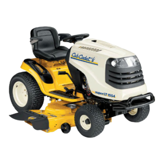
2000 and 2500 and reverse direction and speed. See Figure Series tractors. 1.15. 2.2. The hood presently used on the 1000 series tractors is a molded 1-piece design. See Figure 2.2. Figure 1.15 1.16. A Hydro-Gear 320-3000 hydrostatic transaxle is Figure 2.2... - Page 8 The hood used on the 1500 Series tractors for 2005 and 2006 is more substantial than that used on the 1000 Series. It is a one-piece molded design very similar to the one used on the much larger 5000 and 6000 series tractors.
-
Page 9: Hood Panel Removal: 1500 Series
Series 1000 and 1500 2.7. A torsion spring keeps the latch secure until the 3.2. Disconnect headlight harness (plugged secured lower pivot latch is intentionally pulled up, to to hood lift cylinder). See Figure 3.2. open the hood. See Figure 2.7. Headlight Harness Torsion Spring... -
Page 10: Hood And Hinge Removal: 1500 Series
Series 1000 and 1500 HOOD AND HINGE REMOVAL: 1500 SERIES 4.8. Hood installation notes: See Figure 4.8. NOTE: Use this procedure for more extensive repairs. Typical reasons may include dash panel removal, or the need for more working room than simply removing the hood will provide. 4.1. -
Page 11: Rear Fender Removal
Traction drive belt tension arm removal NOTE: At first-glance, fender removal appears to be a substantial job. Skilled mechanics can typically remove the fenders from a 1000 Series Cub Cadet tractor in about 15 minutes, with an Safety Switch Connectors equal amount of time required for installation. - Page 12 Series 1000 and 1500 5.7. Remove the four bolts that hold the seat brack- 5.12. Peel-back the rubber foot pad to reach and ets to the frame using a 1/2” wrench. remove the carriage bolt. See Figure 5.12. 5.8. Remove the seat to a safe location. 5.9.
-
Page 13: Fuel System
While the 1000 and 1500 Series tractors are built on the same frame, the fuel systems differ substantially in layout. 6.2. The 1000 Series tractors have the fuel tank beneath the hood, with the battery located under the seat. See Figure 6.2. Figure 5.14 5.15. - Page 14 There are a few non-vented fuel caps that will fit the filler neck of the 1000 and 1500 Series trac- tor. • Non-vented caps are used on the Cub Cadet Big Country line of utility vehicles. • Use of a non-vented cap on a 1000 or 1500...
-
Page 15: Fuel Shutoff Solenoid
Series 1000 and 1500 6.15. Remove the plate that supports the seat brack- ets using a 1/2” wrench. See Figure 6.15. • When the solenoid does not have power, it closes, stopping the flow of fuel. • The solenoid usually emits an audible “click” when power is applied or discontinued. -
Page 16: Muffler Removal
9.4. Remove the four screws in the top of the muffler guard. the muffler and muffler guard will now separate. 9.5. Reassemble in reverse order. • 1000 Series with one piece hood. 9.6. Remove hood as shown in section 2. -
Page 17: Cutting Deck Removal
Series 1000 and 1500 9.9. Remove the four screws going through the muf- 9.16. Remove the four screws holding the muffler fler support brackets into the muffler mounting guard to the front muffler support brackets. See bracket. See Figure 9.9. Figure 9.16. - Page 18 Series 1000 and 1500 10.3. Remove the PTO belt from electric PTO clutch. 10.7. Slide the deck forward and release the front sta- See Figure 10.3. bilizer rod. DO NOT DROP the deck to the ground. See Figure 10.7. Electric PTO Idler clutch (earlier production)
-
Page 19: Deck Lift Shaft Assembly
Series 1000 and 1500 DECK LIFT SHAFT ASSEMBLY 11.6. With the deck height control lever all the way for- ward, remove the hairpin clips that secure the 11.1. If the deck lift shaft itself requires removal, first deck lift cables to the arms on the deck lift shaft. remove the cutting deck. -
Page 20: Lift Shaft Bushings
Series 1000 and 1500 11.9. Slide the lift shaft assembly to the right, provid- bushing, it should be a dry graphite or PTFE ing clearance to remove the left end of the shaft based lube. from the frame. See Figure 11.9. •... -
Page 21: Deck Lift Cables And Pulleys
Series 1000 and 1500 12.4. Disconnect the deck lift assist spring that 13.3. Remove the rear tires using a 3/4” wrench. extends from the deck lift shaft to the transaxle See Figure 13.3. torque bracket using a length of starter rope or a spring tool. -
Page 22: Leveling The Cutting Deck
Series 1000 and 1500 13.5. Remove the notched plate that the deck height 13.10. Remove the hairpin clip that secures the pin to control lever seats against in the fender, using a the lift arm, and remove the cable. 1/2” socket. See Figure 13.5. 13.11. - Page 23 Series 1000 and 1500 14.1. Using a work glove or rag, rotate the blades until FRONT TO REAR ADJUSTMENT they are cutting edge tip to cutting edge tip (per- IMPORTANT: The front of the deck will be pendicular) to the tractor. See Figure 14.1. between 1/4”...
-
Page 24: Dash Panel Removal
Series 1000 and 1500 • For the U-bolt style: • For the J-bolt Style: 14.11. Loosen both lock nuts securing the adjustment 14.15. The J-bolt style stabilizer is adjusted in a similar nuts on the front of the deck stabilizer bracket fashion. - Page 25 Molded connectors dash panel. See Figure 15.7. Throttle Lever Figure 15.5 NOTE: Image shows 1500 dash. 1000 series Figure 15.7 dash components are in a similar location. • Key switch and OCR module 15.8. On models with a separate choke cable, discon- •...
-
Page 26: Cruise Control And Park Brake Linkages
AGES Figure 16.5 16.1. Open the hood. 16.2. On the 1000 series you need to remove the fuel 16.6. Remove the hair pin clip in the pivot rod. tank. on the 1500 series you need to remove the 16.7. Work the pivot rod out. sliding it out to the right. - Page 27 Series 1000 and 1500 16.10. Remove the cotter pins in the brake pedal shaft 16.16. Remove the lock nut from the bottom of the and the drive pedal shafts. See Figure 16.10.. steering shaft. Then slide off the steering shaft gear.
-
Page 28: Traction Drive Belt Replacement: Cvt
Series 1000 and 1500 16.19. Pivot the subframe down. Be careful of the 17.3. Remove the battery hold-down, remove the bat- spacer on the bolt and the hex flange bushing for tery and the battery tray. See Figure 17.3. the steering shaft, they will fall out. 16.20. - Page 29 Series 1000 and 1500 17.6. Using the slack created by taking the belt off the 17.8. Lift the sliding center partition of the variable tensioner pulley, slip the belt off of the transaxle speed pulley as far as it will go. This should pro- input pulley and the upper sheave of the variable vide enough clearance to slip the lower belt off of speed pulley and remove the belt from the trac-...
- Page 30 Series 1000 and 1500 17.11. Disconnect the plug for the PTO clutch wire. It is located on the right side of the tractor, just above NOTE: On some models you may have to the opening in the frame that the wire passes remove the belt guide on the engine.
-
Page 31: Drive System Adjustment: Cvt
Series 1000 and 1500 17.15. Remove the belt from the tractor. • The tractor’s forward ground speed should vary smoothly between 0 and 5.2 MPH when the NOTE: There were a small number of tractors drive pedal is depressed progressively to the made using a CVT drive and a 2-speed end of it’s travel. - Page 32 Series 1000 and 1500 • Remove the battery and battery tray from the loads (from torquing the nut) directly to the pul- tractor. ley, not the adaptor. 18.6. Inspect the upper drive belt: See Figure 18.6. 18.8. Repair any problems found. If the upper drive belt is correct and in serviceable condition, rein- stall it.
- Page 33 Series 1000 and 1500 18.11. The empty hole in the double idler bracket 18.15. The forward end of the speed control rod con- should swing through an arc of 1 3/8” when 10 nects to a pin attached to the speed control lbs.
-
Page 34: Brake Adjustment: Cvt
Series 1000 and 1500 BRAKE ADJUSTMENT: CVT 19.8. CVT-driven transaxles use a self locking nut on the brake adjustment. See Figure 19.8. 19.1. On CVT-driven lawn and garden tractors, most of the braking force is generated within the tran- saxle: when the drive pedal is released, the drive ratio changes, slowing the tractor. - Page 35 Series 1000 and 1500 19.13. Check the movement of the brake arm: 19.17. Remove the caliper from the transaxle. The brake actuator arm can now be unhooked from • The brake arm should move forward as the the spring that connects it to the linkage. See brake is applied.
-
Page 36: Servicing The Brake Pedal Shaft Bushings
Series 1000 and 1500 19.19. A crease in the brake arm acts as a cam. At rest, SERVICING THE BRAKE PEDAL SHAFT BUSH- the ends of the two pins ride in the peak of the INGS: crease: See Figure 19.19. •... - Page 37 Series 1000 and 1500 20.4. The inboard brake pedal shaft bushing can be 20.6. Press the brake pedal shaft as far outward as removed by removing the cotter pin and washer possible, and pry the worn bushing out of the that secure it.
-
Page 38: Transaxle Replacement: Cvt
Series 1000 and 1500 21.2. Remove the battery hold down, battery and bat- tery tray from the unit. See Figure 21.2. NOTE: Lubrication with grease may accelerate bushing wear. If lubrication is applied it should be in dry form such as graphite or PTFE (Teflon). 20.8. - Page 39 Series 1000 and 1500 21.4. Using a 7/8 socket and extension, remover the 21.7. Disconnect the brake linkage where it connects nut securing the transmission pulley to the trans- to the brake spring. See Figure 21.7. mission. See Figure 21.4. Transmission pulley Brake linkage Brake linkage...
-
Page 40: Transaxle Service And Internals: Cvt
Series 1000 and 1500 21.12. Using a 1/2” socket and 1/2” wrench, remove the TRANSAXLE SERVICE AND INTERNALS: four hex nuts securing the transmission to the frame. See Figure 21.12. • Transaxles needing service within the warranty period qualify for like-kind exchange. •... - Page 41 Series 1000 and 1500 23.4. Remove the electric PTO clutch from the engine 23.6. Carefully release the spring that maintains ten- crankshaft using a 5/8” wrench. See Figure 23.4. sion on the double idler bracket using a length of starter rope or an appropriate tool. See Figure 23.6.
- Page 42 Series 1000 and 1500 23.8. Slip the crankshaft pulley down far enough to get 23.10. The belt for the G.T. models of the 1500 Series the belt off of the pulley, and remove the belt line is Kevlar wrapped. Substituting the poly- from the crankshaft.
-
Page 43: Drive System Adjustment: Hydrostatic Lt
Series 1000 and 1500 23.13. The double idler pivot bracket is held to the 24.3. There is no adjustment to the relief valve, but full frame by the same bolt that holds the fore-most travel of the linkage should be checked if the of the two pulleys. - Page 44 Series 1000 and 1500 24.7. Turn-off the engine and allow it to cool before 24.15. Set the parking brake, and remove the drive starting to work on the tractor. To gain access to pedal using a T-40 driver. See Figure 24.15. the control linkage, perform the following three steps: T-40 Screws...
- Page 45 Series 1000 and 1500 24.17. Remove the washers and inboard bushings from 24.21. Install the drive pedal, tightening the screw that both shafts. See Figure 24.17. secures it to a torque of 250 in-lbs. 24.22. Move the pedal through it’s range of travel to check for bind.
-
Page 46: Hydro Control Rod Adjustment
Series 1000 and 1500 HYDRO CONTROL ROD ADJUSTMENT 25.5. If there is, thread the ferrule up or down the length of the hydro control rod until the post is • If the unit “creeps” in the neutral position, one of centered in the hole that it fits into. -
Page 47: Brakes And Brake Adjustment: Hydrostatic Lt
Series 1000 and 1500 25.8. As the hydro control rod moves back on the • If the roller is moved lower, the input arm will input arm, it first moves a ground contact against move in the direction that causes reverse drive. the reverse safety switch. - Page 48 Series 1000 and 1500 26.2. When properly adjusted, the brake should do 26.9. Insert a .015” feeler gauge between the brake two things: it should stop and hold the tractor rotor and the outer brake pad. There should be when applied, and it should not drag when slight drag on the feeler gauge.
- Page 49 Series 1000 and 1500 26.16. If the brakes are dragging or worn, or if the rotor 26.20. In order to remove the rotor and gain access to needs to be removed from the shaft disconnect the fixed brake pad you will have to pry the the brake return spring where it attaches to the retaining clip securing the hydro relief arm to the transmission housing.
-
Page 50: Pedal Bushing Replacement
Series 1000 and 1500 26.22. The crease in the brake arm acts as a cam: brakes, a simple visual inspection should identify See Figure 26.22. the cause. 26.31. Confirm that the brake pedal is firmly attached to the pedal shaft. See Figure 26.31. Brake Pedal Figure 26.22 •... -
Page 51: Transaxle Service And Maintenance: Hydrostatic Lt
Series 1000 and 1500 27.3. Remove and discard both cotter pins that secure 27.6. Clean any corrosion or dirt from the surfaces the brake pedal shaft and the hydro drive pedal where the pedal shafts contact the bushings, shaft to the frame. See Figure 27.3. and slip the new bushings into place. - Page 52 Series 1000 and 1500 28.2. Because the transaxle dissipates heat through will fill the over-flow reservoir, but will not add to air-cooling of the housing, it must be kept clean the level of fluid in the transaxle. of dirt and debris, and the cooling fan should be NOTE: This oil (fluid) should not have to be replaced immediately if damaged.
-
Page 53: Transaxle Replacement: Hydrostatic Lt
TRANSAXLE REPLACEMENT: HYDROSTATIC LT Brake rod 29.1. Warrantable failures on Cub Cadet tractors are to be repaired by replacing the transaxle. Failed, warrantable transaxles will be called-back through Cub Cadet’s vendor recovery system. Failures of Hydro-Gear transaxles are rare. - Page 54 Series 1000 and 1500 29.13. Draw the traction drive belt off of the fixed idler 29.17. Disconnect the deck lift assist spring that hooks pulley to create slack, then work the belt off of to the left side of the transaxle torque bracket the double idler pulleys, similar to the method using a length of starter rope or a spring removal described in the “TRACTION DRIVE BELT:...
- Page 55 Series 1000 and 1500 29.19. A length of starter rope is best used to discon- 29.23. Carefully lower the transaxle to the ground, com- nect the front of the spring from the control arm. plete with torque bracket, brake rod, and hydro pass the rope over the torque bracket, and draw control rod.
-
Page 56: Traction Drive Belt Replacement: Hydrostatic Gt
Series 1000 and 1500 TRACTION DRIVE BELT REPLACEMENT: 30.5. Slip the belt off of the single fixed idler. HYDROSTATIC GT See Figure 30.5. 30.1. Turn-off the engine and allow all parts to cool before beginning work. 30.2. Remove the cutting deck. 30.3. - Page 57 Series 1000 and 1500 30.8. Slip the crankshaft pulley down far enough to get 30.10. The belt for the G.T. models of the 1500 Series the belt off of the pulley, and remove the belt line is Kevlar wrapped. Substituting the poly- from the crankshaft.
-
Page 58: Drive System Adjustment: Hydrostatic Gt
Series 1000 and 1500 30.13. The double idler pivot bracket is held to the 31.3. There is no adjustment to the relief valve, but full frame by the same bolt that holds the fore-most travel of the linkage should be checked if the of the two pulleys. - Page 59 Series 1000 and 1500 31.7. Turn-off the engine and allow it to cool before starting to work on the tractor. To gain access to the control linkage, perform the following three steps: 31.8. Remove the cutting deck. 31.9. Lift and safely support the rear of the tractor. 31.10.
- Page 60 Series 1000 and 1500 31.17. Remove the washer and inboard bushing from 31.20. Secure the pedal shaft with a new cotter pin and the pedal shaft. See Figure 31.17. previously removed washer. 31.21. Install the drive pedal, tightening the screw that secures it to a torque of 250 in-lbs.
- Page 61 Series 1000 and 1500 31.28. To adjust the hydro control rod: Find the Neu- 31.31. To adjust the input arm on the hydro: Confirm tral position for the control pedal, and set the that the roller on the return arm draws fully into parking brake.
-
Page 62: Brakes And Brake Adjustment: Hydrostatic Gt
Series 1000 and 1500 31.34. As the hydro control rod is pushed rearward, it 31.37. Loosen the eccentric using a 1/4” Allen wrench, draws the cam (front) surface of the input arm and rotate it to adjust the roller up or down, as upward, forcing the neutral return arm forward, required to center the input arm in Neutral. - Page 63 Series 1000 and 1500 32.5. There is no linkage adjustment. All adjustment 32.12. Tighten the nut to reduce the clearance. Loosen is done at the brake caliper. the nut to increase the clearance. 32.6. To reach the brake caliper, lift and safely support 32.13.
- Page 64 Series 1000 and 1500 32.18. Once the caliper is removed form the transaxle, 32.20. A crease in the brake arm acts as a cam. At rest, the arm can be unhooked from the spring that the ends of the two pins ride in the peak of the connects it to the linkage.
- Page 65 Series 1000 and 1500 32.24. Install the brake caliper, tightening the two nuts 32.30. Remove the cutting deck to reach the brake to 7 to 10 ft.-lbs., then check and adjust the pad- pedal shaft, bushings, and bracket. to-rotor clearance. See Figure 32.24. 32.31.
-
Page 66: Transaxle Service And Maintenance: Hydrostatic Gt
Series 1000 and 1500 32.34. Press the brake pedal shaft as far outward as 32.36. Secure the inner bushing with a new cotter pin possible, and pry the worn bushing out of the and the flat washer that was previously bracket. - Page 67 Series 1000 and 1500 33.6. The transaxle contains .95 gal (116.5 fl.oz) of • To drain the oil and replace the filter: 20W-50 motor oil with an API classification of 33.9. Index-mark the charge pump housing for orien- SH/CD. See Figure 33.6. tation, then remove it using a 5mm Allen wrench.
-
Page 68: Transaxle Replacement: Hydrostatic Gt
Position a new O-ring seal in the charge pump housing, and place the gerotor in the housing. If 34.1. Warrantable failures on Cub Cadet tractors are one edge of the outside of the gerotor is slightly to be repaired by replacing the transaxle. Failed, rounded, it goes into the housing first. - Page 69 Series 1000 and 1500 34.7. Disconnect the front of the brake rod from the 34.12. Disconnect the control rod from the arm on the brake pedal shaft by removing the cotter pin, hydro.: and pulling the “L” at the forward end of the rod •...
- Page 70 Series 1000 and 1500 34.16. Disconnect the hydro relief rod from the relief 34.20. Remove the pair of nuts and bolts that fasten valve by removing the hairpin clip. Lift the rod off each axle housing of the transaxle to the brack- of the arm that controls the valve, and remove ets on the tractor frame.
-
Page 71: Steering Gear And Steering Pinion Gear Replacement
Series 1000 and 1500 34.27. Test run the tractor in a safe are that is free of 35.8. Lower the engine pulley on the crankshaft as obstacles, hazards, and bystanders after the cut- you remove the drive belt from around the pul- ting deck is installed. -
Page 72: Steering Adjustment / Alignment
Series 1000 and 1500 STEERING ADJUSTMENT / ALIGNMENT 36.6. In front of the axle, measure the distance hori- zontally from the inside of the left rim to the IMPORTANT: The front tires will have a “TOE- inside of the right rim. See Figure 36.6. IN”... -
Page 73: Pivot Bar Service
Series 1000 and 1500 36.11. Remove the right hand ball joint from the right 37.1. Loosen the plastic wing nuts securing the side hand drag link. See Figure 36.11. panels to the battery hold down bracket and the grille assembly. See Figure 37.1. Wing Nuts Battery Hold Down Bracket... - Page 74 Series 1000 and 1500 37.5. Disconnect the wiring harness connector from 37.10. Loosen the large hex flange nut securing the left the lighting harness connector. See Figure 37.5. axle assembly to the pivot bar using a 15/16" socket. See Figure 37.10. NOTE: Some models will have a push cap.
-
Page 75: Electrical System
Series 1000 and 1500 37.14. Remove the large hex flange nuts securing the 37.20. Remove both self tapping screws securing the axles to the pivot bar. front pivot axle bracket to the frame using a 1/2" socket. See Figure 37.20. 37.15. - Page 76 Series 1000 and 1500 to, but much less complex than the transition 38.3. The Key Switch is similar to those used in a that the auto industry made with the conversion variety of MTD applications since 1999. The dif- to fuel injection in the 1980s. ference in this case is that it is incorporated in the same housing as the RMC module;...
- Page 77 Series 1000 and 1500 • Symptom-engine runs with key in OFF position: wires where they connect to the S terminal The key switch is not completing the path to (whole circuit) or directly to the afterlife solenoid ground either because of an internal fault or a to listen for the audible “click”...
- Page 78 Series 1000 and 1500 MODE position, the white wire carries a ground 38.8. The RMC Module is in the same housing as the signal to the RMC module. When the parking key switch, and is not available separately. For brake is not set, this ground signal tells arms the purpose of diagnosis it is treated separately.
- Page 79 RMC module if the operator wishes to continue with the ability put the tractor in reverse while the NOTE: For the 1000 series it may be necessary PTO is running. to unfasten the fuel tank and move it aside for easier access to the plug.
- Page 80 Series 1000 and 1500 38.13. Looking at the plug head-on, it will be configured the seat is empty, the switch may be inoperative as shown in the diagram: There will be 8 female or there may be an open condition in the wire pin terminals.
-
Page 81: Understanding The Pto Switch
Series 1000 and 1500 38.18. The red wire on the OCR plug carries battery 39.2. B-COM is in the safety shut-down circuit. It is a voltage. normally opened (NO) set of contacts. A circuit is completed from the M terminal on the key switch •... - Page 82 Series 1000 and 1500 39.4. The Brake Switch is mounted to the inside 39.5. The Reverse Safety Switch is a simple of the frame slightly right of the steering metal contact tang. The gear selector shaft. See Figure 39.4. touches it when placed in the reverse posi- tion, providing a ground path through the gear sector lever itself.
- Page 83 Series 1000 and 1500 39.7. The Seat Safety Switch consists of a pair of 39.8. On the 1000 series tractors the starter solenoid simple metal contact tangs attached to the seat is mounted at the left rear corner of the frame.
- Page 84 Series 1000 and 1500 39.11. The lighting circuit is hot whenever the engine • The red wire with white trace carries fused is running. It does not draw from the battery, but power to the B terminal on the key switch. runs directly off its own circuit on the alternator.
- Page 85 Series 1000 and 1500 39.17. As a point of illustration, a short length of 12 or 39.19. A more effective way to identify this reduced cur- 14 gauge stranded wire can be stripped at the rent carrying capacity is to look for “voltage ends to facilitate an Ohm reading.
- Page 86 Series 1000 and 1500 39.21. As an example, if the starter solenoid does not 39.25. Individually, these readings should lead a techni- engage properly, check for voltage drop between cian to inspect the connection between the sole- the ground point for the starter solenoid and the noid and the ground path (e.g.
- Page 87 Series 1000 and 1500 39.28. As an example, if the tractor had a slow-turning 39.32. Switches may be bench tested using an Ohm starter, the ground-side voltage drop measured meter. Generally speaking, safety switches will have less than 0.2 Ω through the contacts. below 0.1 volts, and there was not a parasitic load on the engine (e.g.
- Page 88 Series 1000 and 1500...
- Page 89 Series 1000 and 1500...
- Page 90 Series 1000 and 1500...
Need help?
Do you have a question about the 1000 SERIES and is the answer not in the manual?
Questions and answers