Toro Power Max 726 OE Operator's Manual
Hide thumbs
Also See for Power Max 726 OE:
- Operator's manual (32 pages) ,
- Operator's manual (32 pages) ,
- Operator's manual (32 pages)
Table of Contents
Advertisement
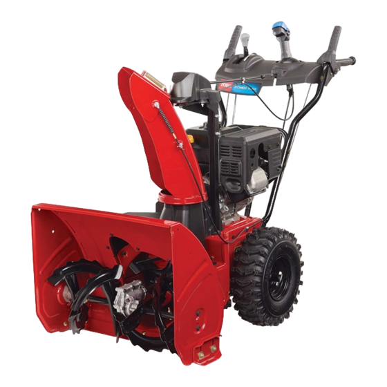
Power Max 726 OE Snowthrower
Model No. 38813—Serial No. 316000001 and Up
This product complies with all relevant European directives.
For details, please see the separate product specific
Declaration of Conformity (DOC) sheet.
Introduction
This machine is intended to be used by residential
homeowners or professional, hired operators. It is
designed primarily for removing snow from paved
surfaces, such as driveways and sidewalks, and other
surfaces for traffic on residential or commercial
properties. It is not designed for removing materials
other than snow, nor is a model with a pivoting scraper
designed for clearing off gravel surfaces.
Read this information carefully to learn how to operate and
maintain your machine properly and to avoid injury and
machine damage. You are responsible for operating the
machine properly and safely.
You may contact Toro directly at www.Toro.com for machine
and accessory information, help finding a dealer, or to register
your machine.
Whenever you need service, genuine Toro parts, or additional
information, contact an Authorized Service Dealer or Toro
Customer Service and have the model and serial numbers of
your machine ready.
Figure 1
model and serial numbers on the machine. Write the numbers
in the space provided.
G016493
1. Model and serial number location
© 2015—The Toro® Company
8111 Lyndale Avenue South
Bloomington, MN 55420
identifies the location of the
ST OP
Figure 1
Register at www.Toro.com.
Model No.
Serial No.
This manual identifies potential hazards and has safety
messages identified by the safety alert symbol
which signals a hazard that may cause serious injury or death
if you do not follow the recommended precautions.
1. Safety alert symbol
This manual uses 2 words to highlight information.
Important calls attention to special mechanical information
and Note emphasizes general information worthy of special
attention.
1
Form No. 3396-510 Rev A
Operator's Manual
Figure 2
Original Instructions (EN)
All Rights Reserved *3396-510* A
Printed in the USA
(Figure
2),
Advertisement
Table of Contents

Related Manuals for Toro Power Max 726 OE


Summary of Contents for Toro Power Max 726 OE
-
Page 1: Introduction
Important calls attention to special mechanical information and Note emphasizes general information worthy of special You may contact Toro directly at www.Toro.com for machine attention. and accessory information, help finding a dealer, or to register your machine. -
Page 2: Table Of Contents
Contents Introduction ..............1 Safety ................3 Sound Pressure ............3 Sound Power ............3 Vibration..............3 Safety and Instructional Decals ......... 4 Setup ................6 1 Installing the Upper Handle........6 2 Installing the Speed Selector Linkage ....... 7 3 Installing the Chute .......... -
Page 3: Safety
Safety Before Operating Caution: Improper use may result in loss of fingers, hands, or feet. Read and understand the contents of this manual before operating the snowthrower There is a high-speed Become familiar with all controls and know impeller close to the how to stop the engine quickly opening. -
Page 4: Safety And Instructional Decals
Safety and Instructional Decals Important: Safety and instruction decals are located near areas of potential danger. Replace damaged decals. 131–6487 1. Engine—stop 3. Fast 2. Slow 121–6817 1. Cutting dismemberment, impeller and cutting dismemberment, auger hazards—keep bystanders a safe distance from the snowthrower. 121–6823 1. - Page 5 121–1240 Order part no. 120–7194 1. Traction drive—squeeze the lever to engage; release the 4. Cutting dismemberment hazard, impeller—keep away lever to disengage. from moving parts; remove the ignition key and read the instructions before servicing or performing maintenance. 2. Warning—read the Operator’s Manual. 5.
-
Page 6: Setup
Setup Loose Parts Use the chart below to verify that all parts have been shipped. Procedure Description Qty. Handle bolts Curved washers Install the upper handle. Locknuts Hairpin cotter Install the traction control linkage. Flat washer Carriage bolt Install the chute. Flat washer Carriage bolts Install the chute control rod. -
Page 7: Installing The Speed Selector Linkage
Installing the Speed Selector Linkage g019378 Figure 6 Parts needed for this procedure: Hairpin cotter 6. Pull up on the speed control rod and insert the trunnion Flat washer into the hole in the speed selector lever (Figure Note: If the trunnion does not fit into the hole Procedure when you lift up on the speed control rod, rotate the trunnion upward or downward on the speed control... -
Page 8: Installing The Chute
Installing the Chute Installing the Chute Control Parts needed for this procedure: Parts needed for this procedure: Carriage bolt Carriage bolts Flat washer Locknuts Procedure Procedure 1. Place the chute on the frame and the align the discharge 1. Unwrap the Quick Stick and rotate it so that it is chute mount to the chute support. -
Page 9: Filling The Engine With Oil
Note: Before starting the engine, check the oil level and add oil if necessary. Use automotive detergent oil with an API service classification of SF, SG, SH, SJ, SL, or higher. Refer to your engine owner's manual. Figure 12 below to select the best oil viscosity for the outdoor temperature range expected: g018885 Figure 10... -
Page 10: Checking The Tire Pressure
2. Install the dipstick securely. 2. Move the speed selector to Position R1; refer to Operating the Speed Selector. Note: Do not spill oil around the oil fill tube; oil could 3. Squeeze the left hand (traction) lever to the hand-grip leak onto traction parts and cause the traction to slip. -
Page 11: Product Overview
Product Overview Figure 17 1. Snow cleanout tool (attached to the handle) Operation Before Operation Safety g018887 • Use extension cords and receptacles as specified by the manufacturer for all machines with electric starting motors. • Do not operate the machine without wearing adequate Figure 15 winter garments. -
Page 12: During Operation
• • For best results, use only clean, fresh, unleaded gasoline Exercise extreme caution when operating on slopes. with an octane rating of 87 or higher ((R+M)/2 rating • Never operate the machine without good visibility or method). light. • Oxygenated fuel with up to 10% ethanol or 15% MTBE •... - Page 13 g019015 Figure 19 To self-propel, axle pin through the holes in the wheel hubs and the inner axle holes (Figure 20). g019014 Figure 20...
-
Page 14: Starting The Engine
Starting the Engine 4. Firmly push in the primer with your thumb 3 times, holding the primer in for a second before releasing it 1. Check the engine oil level. Refer to Checking the each time (Figure 23). Engine Oil Level in Maintenance. 2. -
Page 15: Stopping The Engine
5. Move the choke to the C position (Figure 24). HOKE g019055 Figure 26 1. Electric-starter button 3. Recoil starter 2. Electric starter plug-in Note: To use the electric starter, connect a power cord to the electric starter plug-in first and then to a power outlet. -
Page 16: Operating The Traction Drive
Operating the Traction Drive engine can also be stopped by pulling the ignition key outward to the middle position. CAUTION If the traction drive is not properly adjusted, the machine may move in the direction opposite of what you intended, causing injury and/or property damage. -
Page 17: Operating The Auger/Impeller Drive
Operating the Auger/Impeller Drive 1. To engage the auger/ impeller drive, squeeze the right hand (auger/ impeller) lever to the handgrip (Figure 31). Figure 32 Moving the Discharge Chute Figure 31 Hold the blue trigger cap down and move the Quick Stick to the left to move the discharge chute to the left;... -
Page 18: Unclogging The Discharge Chute
Operating Tips DANGER When the machine is in operation, the impeller and auger rotate and can injure or amputate hands or feet. • Before adjusting, cleaning, inspecting, troubleshooting, or repairing the machine, stop the engine and wait for all moving parts to stop. Disconnect the wire from the spark plug and keep it away from the plug to prevent someone Figure 34... -
Page 19: Preventing Freeze-Up
• Have an Authorized Service Dealer inspect and replace the traction drive belt and/or the auger/impeller drive belt, if necessary. Important: You can find more information about maintaining and servicing your machine at www.Toro.com. Maintenance Safety Read the following safety precautions before performing any maintenance on the machine: •... -
Page 20: Preparing For Maintenance
Preparing for Maintenance 1. Move the machine to a level surface. 2. Stop the engine and wait for all moving parts to stop. Checking the Engine Oil Level Service Interval: Before each use or daily—Check the engine oil level and add oil if necessary. 1. -
Page 21: Checking And Adjusting The Auger/Impeller Cable
Figure 39 Figure 37 3. Loosen or tighten the turnbuckle to adjust the spring length to 7 cm ( 2.75 inches) (Figure 40). 3. Loosen or tighten the turnbuckle to adjust the spring length to 5.5 cm (2.18 inches). Figure 40 1. -
Page 22: Changing The Engine Oil
Engine Oil Capacities Model Engine Oil Capacity 38813 0.50 L (17 oz) 1. Clean the area around the oil drain cap (Figure 43). Figure 41 Figure 43 1. Oil drain cap 3. Remove the pipe plug from the gearbox. 4. Check the oil level in the gearbox. The oil should be 2. -
Page 23: Replacing The Drive Belts
If the auger/impeller drive belt or the traction drive belt an open flame. becomes worn, oil-soaked, or otherwise damaged, go to www.Toro.com for additional service information or have an • Allow the engine to cool before storing it. Authorized Service Dealer replace the belt. -
Page 24: Removing The Machine From Storage
Removing the Machine from Storage Perform the annual maintenance procedures as given in the Recommended Maintenance Schedule. -
Page 25: Troubleshooting
Troubleshooting Problem Possible Cause Corrective Action Electric starter does not turn (electric-start 1. The power cord is disconnected at the 1. Connect the power cord to the outlet models only) outlet or the machine. and/or the machine. 2. The power cord is worn, corroded, or 2. - Page 26 5. Unclog the discharge chute. 6. The auger/impeller drive belt is loose 6. Install and/or adjust the auger/impeller or is off the pulley. drive belt; refer to www.Toro.com for servicing information or take the machine to an Authorized Service Dealer.
- Page 27 The Way Toro Uses Information Toro may use your personal information to process warranty claims, to contact you in the event of a product recall and for any other purpose which we tell you about. Toro may share your information with Toro's affiliates, dealers or other business partners in connection with any of these activities. We will not sell your personal information to any other company.
- Page 28 Toro Product listed below if defective in materials or warranty does not cover the following: workmanship or if the Toro GTS (Guaranteed to Start) engine will not start • Cost of regular maintenance service or parts, such as filters, fuel,...