
Related Manuals for Miller Migmatic 175


Summary of Contents for Miller Migmatic 175
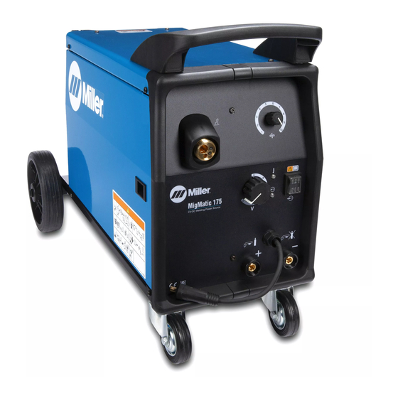
- Page 1 OM-259 158C 2015-06 Processes MIG (GMAW) Welding Flux Cored (FCAW) Welding Description Arc Welding Power Source and Wire Feeder Migmatic 175 OWNER’S MANUAL Visit our website at www.MillerWelds.com...
- Page 2 From Miller to You Thank you and congratulations on choosing Miller. Now you can get the job done and get it done right. We know you don’t have time to do it any other way. That’s why when Niels Miller first started building arc welders in 1929, he made sure his products offered long-lasting value and superior quality.
-
Page 3: Table Of Contents
TABLE OF CONTENTS SECTION 1 − SAFETY PRECAUTIONS - READ BEFORE USING ....... . . 1-1. -
Page 4: Declaration Of Conformity
Council Directive(s) and Standard(s). Product/Apparatus Identification: Product Stock Number MIGMATIC 175, 230VAC 029015550 Council Directives: ·2006/95/EC Low Voltage ·2004/108/EC Electromagnetic Compatibility ·2011/65/EU Restriction of the use of certain hazardous substances in electrical and electronic equipment Standards: ·IEC 60974-1:2012 Arc Welding Equipment –... -
Page 5: Section 1 − Safety Precautions - Read Before Using
SECTION 1 − SAFETY PRECAUTIONS - READ BEFORE USING som 2013−09 Protect yourself and others from injury — read, follow, and save these important safety precautions and operating instructions. 1-1. Symbol Usage DANGER! − Indicates a hazardous situation which, if Indicates special instructions. - Page 6 D Remove stick electrode from holder or cut off welding wire at FUMES AND GASES can be hazardous. contact tip when not in use. D Wear body protection made from durable, flame−resistant material Welding produces fumes and gases. Breathing (leather, heavy cotton, wool). Body protection includes oil-free these fumes and gases can be hazardous to your clothing such as leather gloves, heavy shirt, cuffless trousers, high health.
-
Page 7: Additional Symbols For Installation, Operation, And Maintenance
1-3. Additional Symbols For Installation, Operation, And Maintenance FIRE OR EXPLOSION hazard. MOVING PARTS can injure. D Do not install or place unit on, over, or near D Keep away from moving parts such as fans. combustible surfaces. D Keep all doors, panels, covers, and guards D Do not install unit near flammables. -
Page 8: California Proposition 65 Warnings
1-4. California Proposition 65 Warnings Welding or cutting equipment produces fumes or gases This product contains chemicals, including lead, known to which contain chemicals known to the State of California to the state of California to cause cancer, birth defects, or other cause birth defects and, in some cases, cancer. -
Page 9: Section 2 − Definitions
SECTION 2 − DEFINITIONS 2-1. Additional Safety Symbols And Definitions Some symbols are found only on CE products. Warning! Watch Out! There are possible hazards as shown by the symbols. Safe1 2012−05 Do not discard product (where applicable) with general waste. Reuse or recycle Waste Electrical and Electronic Equipment (WEEE) by disposing at a designated collection facility. -
Page 10: Miscellaneous Symbols And Definitions
Do not weld on drums or any closed containers. Safe16 2012−05 Do not remove or paint over (cover) the label. Safe20 2012−05 <10° Falling unit can cause injury. Do not move or operate unit where it could tip. Safe53 2012−05 Wear hat and safety glasses. - Page 11 Gas Output Positive Negative Gas Type Input Notes OM-259 158 Page 7...
-
Page 12: Section 3 − Specifications
AC 50/60 Hz Range DC Voltage L=769 mm (30.3 Net: 100% in.) 43.3 Kg (95.5 30−150 A W=447 mm MigMatic 175 230 Volts MIG 34 V 15.5−21.0 V (17.6 in.) Ship: 60 A 100 A 150 A H=561 mm 45.4 Kg (100... -
Page 13: Duty Cycle And Overheating
3-4. Duty Cycle and Overheating Duty Cycle is a percentage of 10 min- Rated Output utes that unit can weld at rated load without overheating. If unit overheats, thermostat(s) opens, output stops, and cooling fan runs. Wait fifteen minutes for unit to cool. Reduce amperage or voltage, or duty cycle be- fore welding. -
Page 14: Section 4 − Installation
SECTION 4 − INSTALLATION 4-1. Selecting A Location Line Disconnect Device Locate unit near correct input power supply. Special installation may be required where gasoline or volatile liquids are present − see NEC Article 511 or CEC Section 20. Do not move or operate Tipping unit where it could tip. -
Page 15: Installing Gas Supply
4-2. Installing Gas Supply Obtain gas cylinder and chain to running gear, wall, or other stationary support so cylinder cannot fall and break off valve. Cylinder Valve Remove cap, stand to side of valve, and open valve slightly. Gas flow blows dust and dirt from valve. Close valve. -
Page 16: Changing Drive Roll And Wire Inlet Guide
4-3. Changing Drive Roll and Wire Inlet Guide Wire Guide Securing Screw Inlet Wire Guide Loosen screw. Slide tip as close to drive rolls as possible without touch- ing. Tighten screw. Drive Roll The drive roll consists of two differ- ent sized grooves. -
Page 17: Threading Welding Wire And Adjusting Pressure Roll Tension
4-5. Threading Welding Wire And Adjusting Pressure Roll Tension Wire Spool Welding Wire Inlet Wire Guide Pressure Adjustment Knob Drive Roll Outlet Wire Guide Gun Conduit Cable Lay gun cable out straight. Tools Needed: Hold wire tightly to keep it from unraveling. -
Page 18: Electrical Service Guide
In dedicated circuit installations, the National Electrical Code (NEC) allows the receptacle or conductor rating to be less than the rating of the circuit protection device. All components of the circuit must be physically compatible. See NEC articles 210.21, 630.11, and 630.12. MigMatic 175 50/60 Hz MigMatic Model Single−Phase... - Page 19 Notes OM-259 158 Page 15...
-
Page 20: Connecting 1-Phase Input Power For 230 Vac
4-7. Connecting 1-Phase Input Power For 230 VAC =GND/PE Earth Ground Tools Needed: input4 2012−05 − Ref. 803 766-C / 956142985_2-A OM-259 158 Page 16... - Page 21 4-7. Connecting 1-Phase Input Power For 230 VAC (Continued) See rating label on unit and check input volt- Connect green or green/yellow grounding Installation must meet all National and age available at site. conductor to disconnect device grounding Local Codes − have only qualified per- terminal first.
-
Page 22: Section 5 − Operation
SECTION 5 − OPERATION 5-1. Controls Handle Wire Speed Control 6 Position Voltage Control Thermal Overload Pilot Light Input Voltage Pilot Light Power Switch Negative Power Source Terminal Positive Power Source Connector Polarity Change Over Cable 10 Work Connection 11 Torch Connector Ref. -
Page 23: Section 6 − Maintenance And Troubleshooting
SECTION 6 − MAINTENANCE AND TROUBLESHOOTING Maintain more often Disconnect power before maintaining. during severe conditions. n = Check Z = Change ~ = Clean l = Replace * To be done by Factory Authorized Service Agent Every Months n l Repair or replace n ~ Clean and tighten n l Replace unreadable weld terminals. -
Page 24: Section 7 − Electrical Diagram
SECTION 7 − ELECTRICAL DIAGRAM Ref. 956142984_A Figure 7-1. Circuit Diagram For MigMatic 175 OM-259 158 Page 20... - Page 25 Notes OM-188414 Page 21...
-
Page 26: Section 8 − Parts List
SECTION 8 − PARTS LIST Ref. 956142985-3-A Figure 8-1. Main Assembly Item Dia. Part Mkgs. Description Quantity Figure 8-1. Main Assembly ....207235 . - Page 27 . . . Nameplate, MigMatic 175 ........
- Page 28 19 18 Ref. 956142985_4-A Figure 8-2. Wire Drive Roll (2 Rolls) Item Dia. Part Mkgs. Description Quantity Figure 8-2. Wire Drive Roll (2 Rolls) ... . . 056126082 . . . Motor, Gear .
- Page 29 Item Dia. Part Mkgs. Description Quantity Figure 8-2. Wire Drive Roll (2 Rolls) (Continued) ....156017168 . . . Bearing D.8x 22 ..........
- Page 31 Effective January 1, 2015 (Equipment with a serial number preface of MF or newer) This limited warranty supersedes all previous Miller warranties and is exclusive with no other guarantees or warranties expressed or implied. LIMITED WARRANTY − Subject to the terms and conditions 90 Days —...
- Page 32 File a claim for loss or damage during Phone: 39 (0) 2982901 Fax: 39 (0) 298290-203 shipment. email: miller@itw−welding.it For assistance in filing or settling claims, contact your distributor and/or equipment manufacturer’s Transportation Department. © ORIGINAL INSTRUCTIONS − PRINTED IN USA 2015 Miller Electric Mfg. Co. 2015−01...
Need help?
Do you have a question about the Migmatic 175 and is the answer not in the manual?
Questions and answers