
Related Manuals for Miller Welder


Summary of Contents for Miller Welder
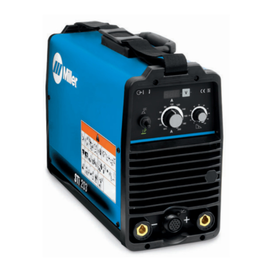
- Page 1 OM-245 849A 2009−11 Processes TIG (GTAW) Welding Stick (SMAW) Welding Description Arc Welding Power Source STi 203...
- Page 2 From Miller to You Thank you and congratulations on choosing Miller. Now you can get the job done and get it done right. We know you don’t have time to do it any other way. That’s why when Niels Miller first started building arc welders in 1929, he made sure his products offered long-lasting value and superior quality.
-
Page 3: Table Of Contents
TABLE OF CONTENTS SECTION 1 − SAFETY PRECAUTIONS - READ BEFORE USING ........1-1. -
Page 4: Declaration Of Conformity
DECLARATION OF CONFORMITY for European Community (CE marked) products. ITW Welding Products Italy S.r.l Via Privata Iseo 6/E, 20098 San Giuliano M.se, (MI) Italy de clares that the product(s) identified in this declaration conform to the essential requirements and provisions of the stated Council Directive(s) and Standard(s). Product/Apparatus Identification: Product Stock Number... -
Page 5: Section 1 − Safety Precautions - Read Before Using
D Do not touch hot parts bare handed. (stick) welder, or 3) an AC welder with reduced open-circuit volt- D Allow cooling period before working on equip- age. In most situations, use of a DC, constant voltage wire welder ment. is recommended. And, do not work alone! - Page 6 D Read and follow instructions on compressed gas cylinders, hazards. associated equipment, and Compressed Gas Association (CGA) D Do not use welder to thaw frozen pipes. publication P-1 listed in Safety Standards. OM-245 849 Page 2...
-
Page 7: Additional Symbols For Installation, Operation, And Maintenance
1-3. Additional Symbols For Installation, Operation, And Maintenance FIRE OR EXPLOSION hazard. MOVING PARTS can injure. D Do not install or place unit on, over, or near D Keep away from moving parts such as fans. combustible surfaces. D Keep all doors, panels, covers, and guards D Do not install unit near flammables. -
Page 8: California Proposition 65 Warnings
1-4. California Proposition 65 Warnings For Gasoline Engines: Welding or cutting equipment produces fumes or gases which contain chemicals known to the State of California to Engine exhaust contains chemicals known to the State of cause birth defects and, in some cases, cancer. (California California to cause cancer, birth defects, or other reproduc- Health &... -
Page 9: Section 2 − Definitions
SECTION 2 − DEFINITIONS 2-1. Warning Label Definitions Warning! Watch Out! There are possible Breathing welding fumes can be 3.3 Do not weld on drums or any closed hazards as shown by the symbols. hazardous to your health. containers. 2.1 Keep your head out of the fumes. Arc rays can burn eyes and injure Electric shock from welding electrode skin. -
Page 10: Weee Symbol (For Products Sold Within The Eu)
2-2. WEEE Symbol (For Products Sold Within The EU) Do not discard product (where ap- plicable) with general waste. Reuse or recycle Waste Electrical and Electronic Equipment (WEEE) by disposing at a designated collec- tion facility. Contact your local recycling office or your local distributor for further information. -
Page 11: Section 3 − Specifications
SECTION 3 − SPECIFICATIONS 3-1. Important Information Regarding CE Products (Sold Within The EU) This equipment shall not be used by the general public as the EMF limits for the general public might be exceeded during welding. This equipment is built in accordance with EN 60974−1 and is intended to be used only in an occupational environment (where the general public access is prohibited or regulated in such a way as to be similar to occupational use) by an expert or an instructed person. -
Page 12: Duty Cycle And Overheating
3-4. Duty Cycle And Overheating Duty Cycle is percentage of 10 min- utes that unit can weld at rated load without overheating. If unit overheats, output stops and cooling fan runs. Wait fifteen min- utes for unit to cool. Reduce amper- age or voltage, or duty cycle before welding. -
Page 13: Section 4 − Installation
SECTION 4 − INSTALLATION 4-1. Serial Number And Rating Label Location The serial number and rating information for the power source is located on the rear of the machine. Use the rating labels to determine input power requirements and/or rated output. For future reference, write serial number in space provided on back cover of this manual. 4-2. -
Page 14: Weld Output Terminals And Selecting Cable Sizes
4-3. Weld Output Terminals And Selecting Cable Sizes* NOTICE − The Total Cable Length in Weld Circuit (see table below) is the combined length of both weld cables. For example, if the power source is 30 m (100 ft) from the workpiece, the total cable length in the weld circuit is 60 m (2 cables x 30 m). Use the 60 m (200 ft) column to determine cable size. -
Page 15: Tig Lift-Arc Dcen (Direct Current Electrode Negative) Connections
4-5. TIG Lift-Arc DCEN (Direct Current Electrode Negative) Connections Turn off power before mak- ing connections. Positive (+) Weld Output Terminal Connect work lead to positive weld output terminal. Negative (−) Weld Output Terminal Connect TIG torch to negative weld output terminal. -
Page 16: Stick Dcep (Direct Current Electrode Positive) Connections
4-6. Stick DCEP (Direct Current Electrode Positive) Connections Turn off power before mak- ing connections. Negative (−) Weld Output Terminal Connect work lead to negative weld output terminal. Positive (+) Weld Output Terminal Connect electrode holder to posi- tive weld output terminal. Remote 14 Receptacle If desired, connect remote control to Remote 14 receptacle (see Sec-... -
Page 17: Connecting Input Power
4-8. Connecting Input Power Installation must meet all National and Local Codes − have only quali- fied persons make this installation. Disconnect and lockout/tagout in- put power before connecting input conductors from unit. Always connect green or green/ yellow conductor supply = GND/PE Earth Ground grounding terminal first, and never... -
Page 18: Section 5 − Operation
SECTION 5 − OPERATION 5-1. Controls Green on nameplate indicates a TIG func- DIG Control The power on light turns on when power is tion, Gray indicates a Stick function. turned on. See Section 5-6. Process Controls High Temperature Shutdown Light Power Switch See Section 5-2. -
Page 19: Process Control
5-2. Process Control Process Control Use the Process control to select the Stick process (up), or the TIG Lift Arc process (down). Stick (SMAW) - This is a DCEP (di- rect current electrode positive) pro- cess. Make connections according to Section 4-6. TIG Lift-Arct - This is a DCEN (di- rect current electrode negative) process in which the electrode... -
Page 20: Stick Start Procedure − Scratch Start Technique
5-4. Stick Start Procedure − Scratch Start Technique With Stick selected, start arc as follows: Electrode Workpiece Drag electrode across workpiece like strik- ing a match; lift electrode slightly after touch- ing work. If arc goes out electrode was lifted to high. -
Page 21: Section 6 − Maintenance And Troubleshooting
SECTION 6 − MAINTENANCE AND TROUBLESHOOTING 6-1. Routine Maintenance Disconnect power before maintaining. Maintain more often during severe conditions. A. Welding Power Source n = Check Z = Change ~ = Clean Δ = Repair l = Replace * To be done by Factory Authorized Service Agent Every Months nl Labels... -
Page 22: Troubleshooting
6-3. Troubleshooting Trouble Remedy No weld output; unit completely Place line disconnect switch in On position (see Section 4-8). inoperative. Check and replace line fuse(s), if necessary, or reset circuit breaker (see Section 4-8). Check for proper input power connections (see Section 4-8). No weld output;... -
Page 23: Section 7 − Electrical Diagrams
SECTION 7 − ELECTRICAL DIAGRAMS 956 142 663-A Figure 7-1. Circuit Diagram OM-245 849 Page 19... -
Page 24: Section 8 − High Frequency
SECTION 8 − HIGH FREQUENCY 8-1. Welding Processes Requiring High Frequency High-Frequency Voltage TIG − helps arc jump air gap between torch and workpiece and/ or stabilize the arc. Work high_freq 7/05 − S-0693 8-2. Incorrect Installation Weld Zone 11, 12 50 ft (15 m) Sources of Direct High-Frequency... -
Page 25: Correct Installation
8-3. Correct Installation Weld Zone 50 ft (15 m) 50 ft (15 m) Ground all metal ob- jects and all wiring in welding zone using #12 AWG wire. Ground workpiece if required by codes. Nonmetal Building Metal Building Ref. S-0695 / Ref. S-0695 High-Frequency Source (welding Conduit Joint Bonding and Grounding Metal Building Requirements... -
Page 26: Section 9 − Selecting And Preparing A Tungsten For Dc Or Ac Welding With Inverter Machines
SECTION 9 − SELECTING AND PREPARING A TUNGSTEN FOR DC OR AC WELDING WITH INVERTER MACHINES gtaw_Inverter_2007-05 Whenever possible and practical, use DC weld output instead of AC weld output. 9-1. Selecting Tungsten Electrode ( Wear Clean gloves To Prevent Contamination Of Tungsten ♦... -
Page 27: Section 10 − Guidelines For Tig Welding (Gtaw)
SECTION 10 − GUIDELINES FOR TIG WELDING (GTAW) 10-1. Positioning The Torch Grinding the tungsten electrode produces dust and flying sparks which can cause injury and start fires. Use local exhaust (forced ventilation) at the grinder or wear an approved respirator. Read MSDS for safety information. -
Page 28: Torch Movement During Welding
10-2. Torch Movement During Welding Tungsten Without Filler Rod ° Welding direction Form pool Tilt torch Move torch to front of pool. Repeat process. Tungsten With Filler Rod ° ° Welding direction Form pool Tilt torch Add filler metal Remove rod Move torch to front of pool. -
Page 29: Section 11 − Stick Welding (Smaw) Guidelines
SECTION 11 − STICK WELDING (SMAW) GUIDELINES 11-1. Stick Welding Procedure Weld current starts when electrode touches work- piece. Weld current can damage electronic parts in vehicles. Disconnect both battery cables before welding on a vehicle. Place work clamp as close to the weld as possible. -
Page 30: Electrode And Amperage Selection Chart
11-2. Electrode and Amperage Selection Chart 3/32 6010 5/32 & 3/16 6011 7/32 6010 DEEP MIN. PREP, ROUGH 1/16 HIGH SPATTER 6011 DEEP 5/64 6013 EP,EN GENERAL 3/32 SMOOTH, EASY, 6013 7014 EP,EN FAST 5/32 3/16 LOW HYDROGEN, 7018 STRONG 7/32 FLAT SMOOTH, EASY,... -
Page 31: Positioning Electrode Holder
11-5. Positioning Electrode Holder ° ° ° ° End View of Work Angle Side View of Electrode Angle GROOVE WELDS ° ° ° ° End View of Work Angle Side View of Electrode Angle FILLET WELDS S-0060 11-6. Poor Weld Bead Characteristics Large Spatter Deposits Rough, Uneven Bead Slight Crater During Welding... -
Page 32: Conditions That Affect Weld Bead Shape
11-8. Conditions That Affect Weld Bead Shape Weld bead shape is affected by electrode angle, arc length, travel speed, and thickness of base metal. Correct Angle ° - ° Angle Too Large Angle Too Small Drag ELECTRODE ANGLE Spatter Normal Too Long Too Short ARC LENGTH... -
Page 33: Butt Joints
11-10. Butt Joints Tack Welds Prevent edges of joint from draw- ing together ahead of electrode by tack welding the materials in posi- tion before final weld. Square Groove Weld Good for materials up to 3/16 in (5 mm) thick. Single V-Groove Weld °... -
Page 34: Weld Test
11-13. Weld Test Vise Weld Joint Hammer Strike weld joint in direction shown. A good weld bends over but does not break. 2 To 3 in (51-76 mm) 2 To 3 in (51-76 mm) 1/4 in (6.4 mm) S-0057-B 11-14. Troubleshooting − Porosity Porosity −... - Page 35 11-16. Troubleshooting − Incomplete Fusion Incomplete Fusion − failure of weld metal to fuse completely with base metal or a preceeding weld bead. Possible Causes Corrective Actions Insufficient heat input. Increase amperage. Select larger electrode and increase amperage. Improper welding technique. Place stringer bead in proper location(s) at joint during welding.
- Page 36 11-19. Troubleshooting − Burn-Through Burn-Through − weld metal melting completely through base metal resulting in holes where no metal remains. Possible Causes Corrective Actions Excessive heat input. Select lower amperage. Use smaller electrode. Increase and/or maintain steady travel speed. 11-20. Troubleshooting − Waviness Of Bead Waviness Of Bead −...
- Page 37 Notes OM-245 849 Page 33...
-
Page 38: Section 12 − Parts List
SECTION 12 − PARTS LIST Hardware is common and not available unless listed. 246 384-A Figure 12-1. Main Assembly OM-245 849 Page 34... - Page 39 199478 ..Label, Miller 6.000 X 2.500 Horizontal ......
- Page 40 Hardware is common and not available unless listed. 246 385-A Figure 12-2. Panel, Front w/Components Item Dia. Part Mkgs. Description Quantity 12-2. Panel, Front w/Components (Figure 12-1 Item 1) ....194242 .
- Page 41 Hardware is common and not available unless listed. Figure 12-3.Panel, Rear w/Components Item Dia. Part Mkgs. Description Quantity Figure 12-3. Panel, Rear w/Components (Figure 12-1 Item 2) ....V16118098 .
- Page 42 Hardware is common and not available unless listed. Figure 12-4. Base Assembly Item Dia. Part Mkgs. Description Quantity Figure 12-4. Base Assembly (Figure 12-1 Item 5) ....156006060 .
- Page 43 Effective January 1, 2009 This limited warranty supersedes all previous Miller warranties and is exclusive with no other guarantees or warranties expressed or implied. LIMITED WARRANTY − Subject to the terms and conditions 90 Days — Parts below, ITW Welding Products Italy warrants to its original retail...
- Page 44 File a claim for loss or damage during Phone: 39 (0) 2982901 Fax: 39 (0) 298290-203 shipment. email: miller@itw−welding.it For assistance in filing or settling claims, contact your distributor and/or equipment manufacturer’s Transportation Department. © ORIGINAL INSTRUCTIONS − PRINTED IN USA 2009 Miller Electric Mfg. Co. 2009−01...
Need help?
Do you have a question about the Welder and is the answer not in the manual?
Questions and answers