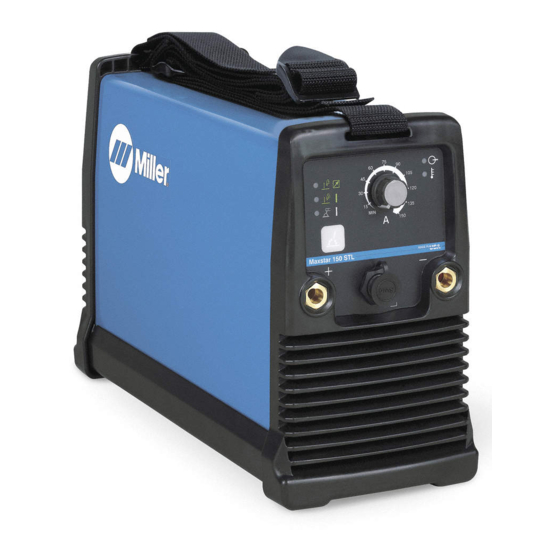
Miller Maxstar 150 STL Owner's Manual
Arc welding power source with auto-line
Hide thumbs
Also See for Maxstar 150 STL:
- Owner's manual (38 pages) ,
- Owner's manual (106 pages) ,
- Owner's manual (102 pages)

Related Manuals for Miller Maxstar 150 STL


Summary of Contents for Miller Maxstar 150 STL
- Page 1 OM-2245 208 726B July 2003 Processes Stick (SMAW) Welding TIG (GTAW) Welding Description Arc Welding Power Source Maxstar 150 STL With Auto-Line Visit our website at www.MillerWelds.com...
-
Page 2: Table Of Contents
TABLE OF CONTENTS SECTION 1 – SAFETY PRECAUTIONS - READ BEFORE USING ......1-1. -
Page 3: Section 1 - Safety Precautions - Read Before Using
SECTION 1 – SAFETY PRECAUTIONS - READ BEFORE USING som _nd_7/02 1-1. Symbol Usage Means Warning! Watch Out! There are possible hazards with this procedure! The possible hazards are shown in the adjoining symbols. This group of symbols means Warning! Watch Out! possible Y Marks a special safety message. - Page 4 ARC RAYS can burn eyes and skin. BUILDUP OF GAS can injure or kill. D Shut off shielding gas supply when not in use. Arc rays from the welding process produce intense D Always ventilate confined spaces or use visible and invisible (ultraviolet and infrared) rays that can burn eyes and skin.
-
Page 5: Additional Symbols For Installation, Operation, And Maintenance
1-3. Additional Symbols For Installation, Operation, And Maintenance FIRE OR EXPLOSION hazard. MOVING PARTS can cause injury. D Do not install or place unit on, over, or near D Keep away from moving parts such as fans. combustible surfaces. D Keep all doors, panels, covers, and guards D Do not install unit near flammables. -
Page 6: Principal Safety Standards
1-4. Principal Safety Standards Safety in Welding, Cutting, and Allied Processes, ANSI Standard Z49.1, Boulevard, Rexdale, Ontario, Canada (phone: from American Welding Society, 550 N.W. LeJeune Rd, Miami FL 33126 800–463–6727 or in Toronto 416–747–4044, website: www.csa–in- (phone: 305-443-9353, website: www.aws.org). ternational.org). -
Page 7: Section 2 - Definitions
SECTION 2 – DEFINITIONS 2-1. Warning Label Definitions A. Warning! Watch Out! There are possible Breathing welding fumes can be 3.3 Do not weld on drums or any closed hazards as shown by the symbols. hazardous to your health. containers. 2.1 Keep your head out of the fumes. -
Page 8: Section 3 - Specifications And Installation
SECTION 3 – SPECIFICATIONS AND INSTALLATION 3-1. Specifications Amperes In- Input Power Welding KVA @ put At Rated Rated Welding Single-Phase Amperage Load Output, Duty Dimensions Weight Output Range 50/60Hz, Cycle Single-Phase 70A @ 22.8 Volts DC, 17.4 100% Duty Cycle 115 Volts Stick 115 Volts Stick 20 –... -
Page 9: Installing Shoulder Strap, Selecting A Location, And Connecting Input Power
3-4. Installing Shoulder Strap, Selecting A Location, And Connecting Input Power Y Do not move or operate unit Welding Power Source Shoulder Strap where it could tip. Use strap to lift unit. Rating Label Label is located on bottom of unit. Use rating label to determine input power needs. -
Page 10: Section 4 - Operation
SECTION 4 – OPERATION 4-1. Front Panel Controls Ready Light M a x star 1 5 0 S TL M a x star 1 5 0 S TL Light comes on approximately two seconds af- ter power switch is placed in On (I) position if Lift-Arc or Stick has been selected. -
Page 11: Set-Up Procedure
4-4. Set-Up Procedure Set-Up Procedure Power Switch Process Switch Pad Ready Light (LED) High Temp Light (LED) Trigger Methods – Choose bet- ween: Standard (remote amper- M IN M IN age and output control), which is the factory default, or Lift Arc Panel Control (for use without a re- mote control or with remote am- perage but without output control). -
Page 12: Section 5 - Maintenance And Troubleshooting
SECTION 5 – MAINTENANCE AND TROUBLESHOOTING 5-1. Routine Maintenance Y Disconnect power before maintaining. Maintain more often during severe conditions. 3 Months Repair Or Replace Replace Replace Damaged Cracked Cables unreadable Gas Hoses And Cords labels. 6 Months Y Do not remove case when blowing out inside of unit . Blow out inside. -
Page 13: Section 6 - Electrical Diagram
SECTION 6 – ELECTRICAL DIAGRAM 208 601-E Figure 6-1. Circuit Diagram For Welding Power Source OM-2245 Page 11... -
Page 14: Section 7 - Parts List
SECTION 7 – PARTS LIST Hardware is common and not available unless listed. 803 474-C OM-2245 Page 12... - Page 15 OM-2245 Page 13...
- Page 19 Effective January 1, 2002 (Equipment with a serial number preface of “LC” or newer) This limited warranty supersedes all previous Miller warranties and is exclusive with no other Warranty Questions? guarantees or warranties expressed or implied. Call LIMITED WARRANTY – Subject to the terms and conditions APT, ZIPCUT &...
- Page 20 Distributor Address City State For Service Call 1-800-4-A-Miller or see our website at www.MillerWelds.com to locate a DISTRIBUTOR or SERVICE AGENCY near you. Always provide Model Name and Serial/Style Number. Contact your Distributor for: Welding Supplies and Consumables Options and Accessories...
Need help?
Do you have a question about the Maxstar 150 STL and is the answer not in the manual?
Questions and answers