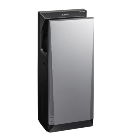
Mitsubishi Electric Jet Towel JT-SB116JH-G-NA Installation Manual
Hand dryer
Hide thumbs
Also See for Jet Towel JT-SB116JH-G-NA:
- Handbook (42 pages) ,
- Installation manual (12 pages) ,
- Instruction manual (8 pages)
Table of Contents
Advertisement
Quick Links
MODEL
JT-SB116JH-G-NA
JT-SB116JH-W-NA
Unit color
-G
(Grey),
INSTALLATION MANUAL
Read this manual thoroughly before beginning installation to ensure the unit is installed safely and correctly.
Local installation standards should be obeyed and installation should be performed by the dealer or a qualifi ed
professional.
The "INSTRUCTION MANUAL" is for the customer. Be sure to hand it to the customer.
INDEX
Safety Precautions ............................................................ 2
Pre-installation checks ...................................................... 3
Names of parts and external dimensions .............................. 4
Installation conditions ......................................................... 5
Installation method ...................................................... 6~11
Test Run ........................................................................ 12
Hand dryer
-W
(White)
....................................... 3
............................................. 5
............................................................... 5
................................................ 5
For Dealers and Installers
............ 3
........................... 3
− 1 −
1311875HF4603
Model Name
Display Position.
Power voltage
display position.
Advertisement
Table of Contents

Related Manuals for Mitsubishi Electric Jet Towel JT-SB116JH-G-NA


Summary of Contents for Mitsubishi Electric Jet Towel JT-SB116JH-G-NA
-
Page 1: Table Of Contents
1311875HF4603 Hand dryer MODEL Model Name Display Position. JT-SB116JH-G-NA Power voltage display position. JT-SB116JH-W-NA Unit color (Grey), (White) INSTALLATION MANUAL For Dealers and Installers Read this manual thoroughly before beginning installation to ensure the unit is installed safely and correctly. Local installation standards should be obeyed and installation should be performed by the dealer or a qualifi... -
Page 2: Safety Precautions
Safety Precautions Warning The following may lead to death or serious personal injury if the unit is handled incorrectly. Do not install in locations where salt damage may Electrical wiring work should be done by a certifi ed occur, or where corrosive, neutral, or reductive professional in conformance with the technical gases are present. -
Page 3: Pre-Installation Checks
Pre-installation checks ■ Checking the installation environment Do not install in the following types of location. (This may cause malfunctions.) Outdoors Locations where the temperature could be lower than 50ºF (10ºC). Locations where there is a lot of dust. Locations where the temperature could be higher than 104ºF (40ºC). Locations where there is a lot of condensation. -
Page 4: Names Of Parts And External Dimensions
Names of parts and external dimensions Refer to the "Installation conditions" on page 5. 10³₈"(263mm) ¹₈"(3mm) 8⁵₈"(219mm) 3¹₁₆" 3¹¹₁₆" (77mm) (93mm) Electrical Conduit/Tubing ¹₂"(16mm) Connector Drain tank 7⁷₁₆" ※ 11¹³₁₆"(300mm (189mm) Air fi lter (air intake) ※ Maximum width in. (mm) of main unit ■... -
Page 5: Installation Conditions
Installation conditions ■ Required space for installation min. min. Electrical (232) (368) ⁄ " ⁄ " Be sure to secure at least the distances Cautions Conduit/Tubing listed in the right-hand figure from walls, flammable (combustible) materials and so on. Ensure a distance of at least 5¹₈"(130mm) from the floor. -
Page 6: Installation Method
Installation method Caution Warning Do not install when the product (power cable) is This hand dryer must have its own independent electrifi ed. branch circuit using AWG #12 or #14 copper wire. Doing so may result in electric shocks. Use 120 Vac power. Using the incorrect power supply may cause fi... - Page 7 Installation (Continued) 3.Remove the terminal cover mounting screw (1), and remove the terminal cover. Rubber bushing Terminal cover mounting screw ※ Be careful not to lose the rubber bushing. Terminal cover Terminal block Warning This hand dryer must have its own independent branch circuit using AWG #12 or #14 copper wire. Use 120 Vac power.
- Page 8 Installation (Continued) 3.For plaster or drywall construction, ⁄ " position at least one side of the back panel (10) holes over the wooden studs for better securement. (297) ⁄ " Detailed view of 4.From the 7 possible hole locations on the installation hole back panel, mark the 7 drill hole positions on the wall and remove the back panel.
- Page 9 Installation (Continued) 1.Screw the power cable to the terminal block. Proper torque is 11 lbf·in(1.2N·m) Green striped bonding wire Terminal block Power cable Terminal Screw block Power cable 2.Check that the power cable is securely fi xed to the terminal block. 3.Screw the green striped bonding wire to the Terminal base terminal base.
- Page 10 Installation (Continued) Back panel Fix the main unit in place. 1.Engage the panel hooks of the installation panel (2 hooks) on the back of the unit. Panel hooks If the wall is concrete, use commercially available metal screw plugs. Use a screwdriver that is longer than 6"(150mm). Power cable Green striped 2.Check that the power cable is not trapped...
- Page 11 Installation (Continued) 1.Engage the groove of the front panel on the unit. 2.Reattach the front panel with the front Groove Main unit panel mounting screws (2). 3.Check that the front panel is fi tted securely. Front panel Front panel mounting screws 4.Attach the air fi...
-
Page 12: Test Run
Test Run Step What to check for Check 120 Vac power being used? Check the power supply voltage Incorrect power supply may cause malfunctions. Turn the ground-fault circuit interrupter is "ON" Maintenance switch is "OFF" Insert your hands to check if air is Is the air blowing? being blown.