Table of Contents
Advertisement
Quick Links
Advertisement
Table of Contents

Related Manuals for Makita EW120R


Summary of Contents for Makita EW120R
-
Page 1: Instructions For Use
PUMP INSTRUCTIONS FOR USE MANUEL D'UTILISATION 9ZZ9990030 アメリカ&カナダ... -
Page 2: Air Index
WARNING : The engine exhaust from this product contains chemicals known to the State of California to cause cancer, birth defects or other reproductive harm. FEDERAL EMISSION COMPONENT DEFECT WARRANTY and CALIFORNIA EMISSION CONTROL WARRANTY are applicable to only those engines/ generators complied with EPA (Environmental Protection Agency) and CARB (California Air Resources Board) emission regulations in the U.S.A. - Page 3 For the components listed under PARTS COVERED, the Makita Factory Service Center or Service Center authorized by MAKITA will, at no cost to you, make the necessary diagnosis, repair, or replacement necessary to ensure that the engine complies with applicable U.S. EPA regulations.
- Page 4 As the engine owner, you are responsible for the performance of the required maintenance listed in your owner's manual. MAKITA recommends that you retain all receipts covering maintenance on your engine, but MAKITA cannot deny warranty solely for the lack of receipts or for your failure to ensure the performance of all scheduled maintenance.
- Page 5 HOW TO MAKE A CLAIM All repair qualifying under this limited warranty must be performed by a Makita Factory Service Center or Service Center authorized by MAKITA. In the event that any emission-related part is found to be defective during the warranty period, you shall notify Makita Warranty Department at 1-800-4-MAKITA and you will be advised of the appropriate warranty service dealer or service providers where the warranty repair can be performed.
-
Page 6: California Emission Control Warranty Statement
Also included are the hoses, belts, connectors and other emission-related assemblies. Where a warrantable condition exists, MAKITA will repair your engine at no cost to you including diagnosis, parts and labor. MANUFACTURER'S WARRANTY COVERAGE : 2005 and later engines are warranted for two years. -
Page 7: Limited Warranty
This warranty period begins on the date which the engine is delivered to the original retail pur- chaser and ends two years after that date. During this two year period MAKITA warrants to the original retail purchaser and each subsequent purchaser that the engine is free from defect in material and workmanship that can cause the failure of a warranted emission-related part. - Page 8 When an engine is being serviced under warranty, MAKITA and any of its authorized dealers, distributors, or warranty stations shall not be liable for any loss of use of the engine, for any damage to goods, or loss of time or inconvenience.
- Page 9 It is recommended that only engine replacement parts which have been authorized and approved by MAKITA should be used in the performance of any warranty maintenance or repairs of emission-related parts. These replacement parts will be provided at no charge if the part is still under warranty.
- Page 10 FACTORY SERVICE CENTERS IN CANADA BRITISH COLUMBIA RICHMOND (Vancouver Regional Office) 11771 Hammersmith Way, Richmond, V7A.5H6 Tel. 1.800.663.0909 or 604.272.3104 Fax.604.272.5416 COQUITLAM Unit 103. 2131 Hartley Avenue, Coquitlam, V3K.2Z3 Tel. 604.525.7434 or 1.800.266.7738 Fax.604.525.7435 ALBERTA CALGARY #8-6115 Fourth Street S.E., Calgary, T2H.2H9 Tel.
-
Page 11: Table Of Contents
Thank you very much for purchasing a MAKITA PUMP. This manual covers operation and maintenance of MAKITA PUMP. All information in this publication is based on the latest product information available at the time of approval for printing. Please read this manual carefully before operating. -
Page 12: Safety Precautions
1. SAFETY PRECAUTIONS Please make sure you review each precaution carefully. Pay special attention to statement preceded by the following words. “WARNING” indicates a strong possibility of severe personal injury or loss of WARNING life if instructions are not followed. “CAUTION”... - Page 13 WARNING : OTHER SAFETY PRECAUTIONS Be careful of hot parts. ■ The muffler and other engine parts become very hot while the is running or just after it has stopped. Operate the pump in a safe area and keep children away from the running pump. Do not use diaphram pump for the mixture of water and oil.
-
Page 14: Components
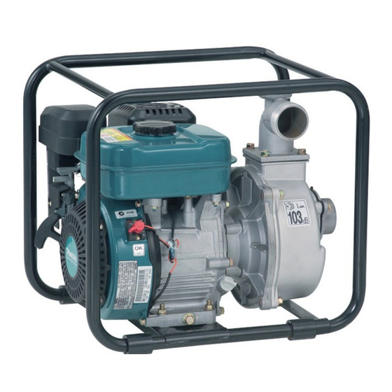
2. COMPONENTS EW120R Handle Plug (priming) Delivery Suction Plug (drain) Choke lever Recoil starter handle Recoil starter Oil filler (with oil gauge) Strainer Spark plug cover Casing cover Fuel tank Speed control lever Muffler Set base Hose band Hose coupling −... - Page 15 EW220R Plug (priming) Frame Delivery Suction Plug (drain) Speed control lever Air cleaner Chocke lever Fuel cock Recoil Starter handle Recoil starter Strainer Hose coupling Muffler Stop Switch Oil drain plug (at two places) Tools Hose band − 4− Spark plug Fuel tank Casing cover Oil filler...
- Page 16 EW320TR Frame Suction Casing Plug (drain) Speed control lever Chocke lever Fuel cock Recoil Starter handle Recoil Starter Strainer Hose coupling Plug (priming) Muffler Casing cover Fuel tank Stop switch Oil filler (with oil guage) Hose band − 5− Air cleaner Spark plug Oil drain plug (at two places)
-
Page 17: Preparations For Starting
3. PREPARATIONS FOR STARTING CONNECT SUCTION HOSE Use a reinforced-wall or wire braided hose to prevent suction collapse. Since the pump's self-priming time is directly proportional to hose length, a short hose is recommended. CAUTION Always use a strainer with the suction hose. -
Page 18: Check Engine Oil
(SG, SH or SJ is recommended). Select the viscosity based on the air ■ temperature at the time of operation as shown in the table. Oil capacity EW120R 2.7 oz (0.08 L) EW220R 20.3 oz (0.6 L) EW320TR 33.8 oz (1.0 L) - Page 19 1.6 U.S.gal (6.1L) Incline the engine as fuel inlet upward, ■ then refill fuel to the upper level. Do not fill fuel too much. (EW120R) Close the fuel cock before filling the ■ fuel tank. (EW220R,EW320TR) Do not fill above the top of the fuel ■...
- Page 20 CHECK PRIMING WATER It is recommended that the water chamber of pump casing should be primed with full of water before operating. WARNING Never attempt to operate the pump without priming water or the pump will overheat. Extended dry operation will destroy the mechanical seal.
-
Page 21: Operation ・ ・ ・ ・ ・ ・ ・ ・ ・ ・ ・ ・ ・ ・ ・ ・ ・ ・ ・ ・ ・ ・ ・ ・ ・10
1. STARTING (a) Open the fuel cock. (EW220R,EW320TR) (b) Set the speed control lever to the idling position (L). (EW120R) Set the speed control lever 1/3 of the way towards the high speed position. (EW220R,EW320TR) (c) Turn the STOP SWITCH to the position “... - Page 22 (d) Close the choke lever. If the engine is cold, or the ambient ■ temperature is low, close the choke lever fully. If the engine is warm or the ambient ■ temperature is high, close the choke half-way, or keep it fully open. (e) Pull the starter handle slowly until resistance is felt.
- Page 23 2. RUNNING (a) After the engine starts, set the speed control lever at the low speed position (L) and warm it up without load for a few minutes. (b) Gradually move the speed control lever toward the high speed position (H) and set it at the required engine speed.
- Page 24 (a) Set the speed control lever at the low speed position and allow the engine to run at low speed for 2 or 3 minutes before stopping. (EW120R) Set the speed control lever at the low speed position and allow the engine to run at low speed for 1 or 2 minutes before stopping.
- Page 25 (d) Pull the starter handle slowly and return the handle to its original position when resistance is felt. This operation is necessary to prevent outside moist air from intruding into the combustion chamber. ※STOPPING ENGINE WITH THE FUEL COCK (EW220R,EW320TR) Close the fuel cock and wait for a while until the engine stops.
-
Page 26: Maintenance Schedule ・ ・ ・ ・ ・ ・ ・ ・ ・ ・ ・ ・ ・ ・ ・ ・15
5. MAINTENANCE SCHEDULE MAINTENANCE, REPLACEMENT OR REPAIR OF THE EMISSION CONTROL DEVICES AND SYSTEMS MAY BE PERFORMED BY ANY NONROAD ENGINE REPAIR ESTAB- LISHMENT OR INDIVIDUAL. DAILY INSPECTION Before running the engine pump, check the following service items: Check priming water Clean air cleaner element Enough gasoline Loose or broken bolts and nuts... - Page 27 Your local zoning or environmental regulations will give you more detailed instructions on proper disposal. *NOTE: 2. As to the procedures for these items, please refer to the SERVICE MANUAL or consult your nearest Makita service dealer. Every Every...
-
Page 28: How-To" Maintenance・ ・ ・ ・ ・ ・ ・ ・ ・ ・ ・ ・ ・ ・ ・ ・ ・17
■ Adjust the gap, if necessary, by carefully bending the side electrode. Use a proper spark plug ■ Model Type EW120R NGK CMR6A NGK BR-6HS EW220R (CHAMPION RL86C) EW320TR ENGINE OIL CHANGE Initial oil change : After 20 hours of operation... - Page 29 (d) Procedures for EW120R 1) Remove the oil gauge. Be cautious to place the oil gauge in a place where it will not gather dirt, dust or other foreign matter. 2) Place a cloth or paper towel to the area around the oil filler hole.
- Page 30 CLEANING FUEL FILTER (EW120R) (a) Remove the hose clamp and pull out the fuel filter from fuel pipe. (b) Wash the fuel filter with kerosene. (c) After washing, reassemble it. If the fuel filter is heavy dirty, replace it with new one.
- Page 31 CLEANING AIR CLEANER A dirty air cleaner element will cause starting difficulty, power loss, engine malfunctions, and shorten engine life extremely. Always keep the air cleaner element clean. EW120R Remove the fixing bolt of air cleaner ■ cover. Pull out the lower edge of the cover to ■...
- Page 32 EW220R, EW320TR (a) Urethane Foam Element Type Remove the element and wash it in ■ kerosene or diesel fuel. Then saturate it in a mixture of 3 parts kerosene or diesel fuel and 1 part engine oil. Squeeze the element to remove the mixture and install it in the air cleaner.
- Page 33 FUEL HOSE REPLACEMENT WARNING Take extreme caution when replacing fuel hose ; gasoline is flammable. Replace the fuel hose every 1,000 hours or every year. If the fuel hose leak is found, replace the fuel hose immediately. CHECKING BOLTS, NUTS AND SCREWS Retighten loose bolts and nuts.
-
Page 34: Preparations For Storage ・ ・ ・ ・ ・ ・ ・ ・ ・ ・ ・ ・ ・23
: Flame Prohibited If you do not use the engine more than 1 month, discharge fuel to prevent gum in the fuel system and carburetor parts. EW120R Pour out the fuel in the tank from its ■ filler neck. Push the primer pump of the carbure- ■... -
Page 35: Engine Oil
EW220R,EW320TR Remove the strainer cup, place the ■ strainer over a container and open the strainer cock to discharge fuel from the fuel tank. Remove the drain screw of the ■ carburetor float chamber and discharge fuel. 4. ENGINE OIL Change the engine oil with fresh oil. -
Page 36: Oil Sensor (Optional) ・ ・ ・ ・ ・ ・ ・ ・ ・ ・ ・ ・ ・ ・ ・ ・ ・25
8. OIL SENSOR (OPTIONAL) 1. FUNCTION OF OIL SENSOR ( EW220R,EW320TR ) The engine will stop automatically when the oil level falls below the safety limit. The engine cannot be started unless the level is raised above the prescribed limit. 2. -
Page 37: Spark Arrester (Optional) ・ ・ ・ ・ ・ ・ ・ ・ ・ ・ ・ ・ ・26
9. SPARK ARRESTER (OPTIONAL) SPARK ARRESTER In a dry or wooded area, it is recommendable to use the Some areas require the use of a spark arrester. Please check your local laws and regulations before operating your prodoct. The spark arrester must be cleaned regularly to keep it functioning as designed. A clogged spark arrester : Prevents the flow of exhaust gas ●... -
Page 38: Troubleshooting ・ ・ ・ ・ ・ ・ ・ ・ ・ ・ ・ ・ ・ ・ ・ ・ ・ ・ ・ ・27
10. TROUBLESHOOTING Pump dose not run. Pumping volume is small Pump dose not self- prime Engine dose not start. (See page 28) Sticking of impeller (Disassemble and clean.) Sucking air at suction side. (Check piping at suction side.) Drop in engine output (Consult your nearest dealer.) Breakage of mechanical seal. - Page 39 3. The ignition system is faulty if there is no spark with a new plug. Take your pump to your nearest Makita dealer. 1. Pull the starter handle slowly and check if resistance is felt. 2. If little force is required to put the starter han- dle check if the spark plug is tightened firmly.
-
Page 40: Specifications ・ ・ ・ ・ ・ ・ ・ ・ ・ ・ ・ ・ ・ ・ ・ ・ ・ ・ ・ ・ ・ ・29
Starting System Length Width Hight Dry Weight Standard Accessories Valve Clearance (Intake and Exhaust) Emissions Durability Period (California only) EW120R Self-Priming, Centrifugal pump 1 x 1 in. in. (mm) (25.4 x 25.4 mm) 115 (35) ft (m) U.S.gal/min (L / min) - Page 41 ISSUE EMD-PU2034 Makita Corporation 3-11-8, Sumiyoshi-cho Anjo, Aichi 446-8502 Japan PRINTED IN JAPAN December 2004...