Advertisement
Quick Links
T
ECHNICAL INFORMATION
Model No.
Description
C
ONCEPT AND MAIN APPLICATIONS
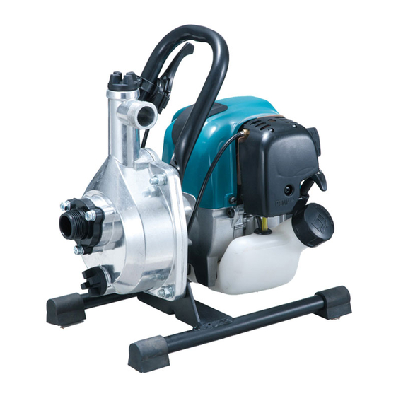
Model EW1050H is 24.5cc 4-stroke engine pump to comply with
all major exhaust emission regulations in the world.
It features the same pumping capacity as the predecessor EW120R,
but it is more cost effective than EW120R.
This product is also available with nozzle and 8m delivery hose
as Model EW1050HX.
S
pecification
Specifications
Type
Displacement: cm³ (cu.in.)
Engine
Fuel
Max. output: kW (PS)
Max. torque: N·m
Speed at no load: min.
In compliance with exhaust emission regulations:
CARB Tier 3, EPA Phase 2, EU Stage 2
Fuel tank capacity: L (US oz)
Engine oil
Carburetor
Starting system
Primer pump
Max. total head: m (ft)
Max. suction head: m (ft)
Max. pumping capacity: L/min (US oz/min)
Suction & discharge diameter: mm (")
Net weight*
: kg (lbs)
3
*2 Brazil: 25E gasoline
*3 Dry weight, without suction hose
S
tandard equipment
Suction hose .......................... 1
Socket wrench ....................... 1
Hose coupling ....................... 2 (for some countries only)
Rapid type hose coupling ...... 2 (for some countries only)
1 inch NPT adapter ............... 1 (for Canada, Mexico, Colombia, Chile, Peru and Brazil only)
Hose band ............................. 3
Strainer ................................. 1
Delivery hose (8m) ............... 1 (for EW1050HX only)
Nozzle ................................... 1 (for EW1050HX only)
Note: The standard equipment for the tool shown above may vary by country.
O
ptional accessories
Rapid type Hose coupling set
Coupling for water supply hose (with Hose band)
8m Delivery hose (with Nozzle)
1 inch NPT adapter
EW1050H
Engine Pump
Model
¹ = rpm
ˉ
EW1050H
4-stroke
24.5 (1.5)
Straight unleaded gasoline*
0.71 (1.0) [at 7,000 min.
1.0 [at 5,500 min.
7,000
Yes
0.5 (16.9)
SAE10W-30 oil
in the class SF or higher of API Classification
Diaphragm
Recoil starter, with mechanical decompression
Yes
35 (115)
8.0 (26)
110 (3,700)
25.4 (1)
5.8 (12.8)
PRODUCT
H
W
Dimensions*
: mm (")
1
Length (L)
327 (12-7/8)
Width (W)
231 (9-1/8)
Height (H)
319 (12-1/2)
*1 without suction hose
2
¹]
ˉ
¹]
ˉ
P 1/ 10
L
Advertisement

Related Manuals for Makita EW1050H


Summary of Contents for Makita EW1050H
- Page 1 EW1050H Description Engine Pump ONCEPT AND MAIN APPLICATIONS Model EW1050H is 24.5cc 4-stroke engine pump to comply with all major exhaust emission regulations in the world. It features the same pumping capacity as the predecessor EW120R, Dimensions* : mm (") but it is more cost effective than EW120R.
-
Page 2: Pump Section
P 2/ 10 epair [3] DISASSEMBLY/ASSEMBLY [3] -1. Pump Section DISASSEMBLING (1) Remove M8 Hex nut ( 4 pcs. in total) in order to separate Pump case and Shelf group from Engine section. And disassemble Pump frame and Volute as drawn in Fig. 1. Fig. - Page 3 P 3/ 10 epair [3] DISASSEMBLY/ASSEMBLY [3] -1. Pump Section (cont.) DISASSEMBLING (2) Remove Refueling winding from Refueling handle group and from Carburetor as drawn in Fig. 2. Fig. 2 1. Remove Air cleaner cover by unscrewing M5x14 Pan head screw. Then remove Refueling winding from Carburetor.
- Page 4 P 4/ 10 epair [3] DISASSEMBLY/ASSEMBLY [3] -1. Pump Section (cont.) DISASSEMBLING (3) Disassemble Impeller and Pump frame as drawn in Fig. 3. Fig. 3 1. After removing Spark plug, drive 1R372 to 3. Apply 1R090 to the rib (Fin) of Impeller, then turn the place where Spark plug was mounted.
- Page 5 P 5/ 10 epair [3] DISASSEMBLY/ASSEMBLY [3] -1. Pump Section (cont.) ASSEMBLING (1) Assemble Refueling handle group to Handle as drawn in Fig. 4. Fig. 4 2. Assemble Refueling handle group to Handle with 1. When the lever of Refueling handle group is fully Pan head screw.
- Page 6 P 6/ 10 epair [3] DISASSEMBLY/ASSEMBLY [3] -1. Pump Section (cont.) ASSEMBLING (4) Assemble Pump frame as drawn in Fig. 7. Fig. 7 Wad (Wave washer) Gasket (Flat washer) 1. Pass each M5x25 Hex bolt through O ring Wave washer, Flat washer and O ring. Note: Be careful not to give damage to O ring when mounting it to the bolt.
- Page 7 P 7/ 10 epair [3] DISASSEMBLY/ASSEMBLY [3] -1. Pump Section (cont.) ASSEMBLING (5) Assemble Impeller and Volute to Pump frame as drawn in Fig. 9. Fig.9 1. Mount Impeller to the drive shaft of the Engine by turning it clockwise until it is seated on. Impeller 2.
- Page 8 P 8/ 10 epair [3] DISASSEMBLY/ASSEMBLY [3] -1. Pump Section (cont.) ASSEMBLING (7) Assemble Shelf group as drawn in Fig. 11, and check the condition of Impeller, in case of replacing the Engine to the new one. Fig. 11 1. Assemble Shelf group to the machine 2.
- Page 9 P 9/ 10 epair [3] DISASSEMBLY/ASSEMBLY [3] -1. Pump Section (cont.) ASSEMBLING (8) Assemble Refueling winding to Refueling handle group as drawn in Fig. 12. Fig. 12 1. Align the hole for Stopper of Refueling winding to the curve of Refueling handle group.
- Page 10 [3] DISASSEMBLY/ASSEMBLY [3] -2. Difference between Engine EH025P for EW1050H and EH025 for Brush cutters EH025P is different from EH025 as drawn in Fig. 14. After removing Blower housing, separate two M6x16 Pan head screws and Shaft from Flywheel. The other disassembly/ assembly is the same as Makita brush cutters Fig.