Table of Contents
Advertisement
Quick Links
Advertisement
Table of Contents

Related Manuals for Makita BLS712


Summary of Contents for Makita BLS712
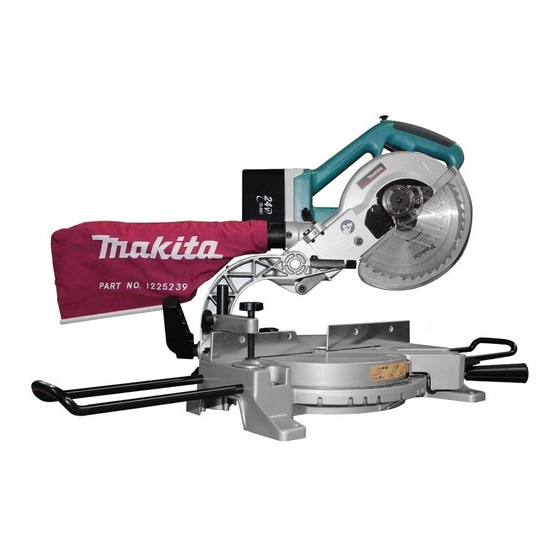
- Page 1 Cordless Slide Compound Saw Equipped with Electric Blade Brake 190 mm (7-1/2”) MODEL BLS712 002165 I N S T R U C T I O N M A N U A L WARNING: For your personal safety, READ and UNDERSTAND before using.
-
Page 2: Specifications
SPECIFICATIONS Blade diameter ... 190 mm (7-1/2”) Hole (arbor) diameter ... 15.88 mm (5/8”) Max. Miter angle ...Left 47°, Right 57° Max. Bevel angle ...Left 45° Max. Cutting capacities (H x W) with blade 190 mm (7-1/2”) in diameter. Bevel angle Miter angle 0°... -
Page 3: General Safety Precautions
For Your Own Safety Read Instruction Manual Before Operating Tool Save it for future reference GENERAL SAFETY PRECAUTIONS (For All TOOIS) 1. KNOW YOUR POWER TOOL. Read the owner’s manual carefully. Learn the tool’s applications and limitations, as well as the specific potential hazards peculiar to it. - Page 4 18. NEVER STAND ON TOOL. Serious injury could occur if the tool is tipped or if the cutting tool is unintentionally contacted. 19. CHECK DAMAGED PARTS. Before further use of the tool, a guard or other part that is damaged should be carefully checked to determine that it will operate properly and perform its intended function - check for alignment of moving parts, binding of...
- Page 5 and pitch remover, hot water or kerosene. Never use gasoline to clean blade. 14. While making a slide cut, KICKBACK can occur. KICKBACK occurs when the blade binds in the workpiece during a cutting operation and the saw blade is driven back rapidly towards the operator.
- Page 6 (1) battery charger, (2) battery, and (3) product using battery. 3. CAUTION - To reduce risk of injury, charge only MAKITA rechargeable marked on the charger label. Other types of batteries may burst causing personal injury and damage.
- Page 7 12. To reduce risk of electric shock, unplug charger from outlet before attempting any maintenance or cleaning. Turning off con- trols will not reduce this risk. 13. The battery charger is not intended for use by young children or infirm persons without supervision.
- Page 8 SYMBOLS The following show the symbols used for the charger. Be sure that you understand their meaning before use..Ready to charge ... Charging ... Charging complete ...Delay charge (Cooling) ...Defective battery ...Conditioning ...Cooling abnormality...
- Page 9 INSTALLATION 002193 1. Stopper Pin 002194 1. Bolt FUNCTIONAL DESCRIPTION 001803 1. Button 2. Battery cartridge 3. Red part Bench mounting When the tool is shipped, the handle is locked in the lowered position by the stopper pin. Release the stopper pin by lower- ing the handle slightly and pulling the stopper pin.
- Page 10 6. After charging, unplug the charger from the power source. NOTE: • The battery charger is for charging Makita battery cartridge. Never use it for other purposes or for other manufacturer’s batteries. • When you charge a new battery cartridge or a battery cartridge which has not been used for a long period of time, it may not accept a full charge.
- Page 11 • If the charging light flashes alternately in green and red color, charging is not possible. The terminals on the charger or battery cartridge are clogged with dust or the battery cartridge is worn out or damaged. Cooling system • This charger is equipped with cooling fan for heated battery in order to enable the battery to prove its own performance.
- Page 12 002245 1. Blade guard Trickle charge (Maintenance charge) If you leave the battery cartridge in the charger to prevent spontaneous discharging after full charge, the charger will switch into its “trickle charge (maintenance charge)” mode and keep the battery cartridge fresh and fully charged. Tips for maintaining maximum battery life 1.
- Page 13 Do not remove spring holding blade guard. If guard becomes discolored through age or UV light exposure, con- tact a Makita service center for a new guard. DO NOT DEFEAT OR REMOVE GUARD. Positioning kerf board This tool is provided with the kerf boards in the turn base to minimize tearing on the exit side of a cut.
- Page 14 002196 1. Adjusting bolt 2. Guide fence 3. Turn Base 001540 1. Top surface ot turn base 2. Periphery of blade 3. Guide fence 002241 1. Adjusting screw 2. Stopper arm Maintaining maximum cutting capacity This tool is factory adjusted to provide the maximum cutting capacity for a 190 mm (7-1/2”) saw blade.
- Page 15 002197 1. Turn base 2. Miter scale 3. Pointer 4. Grip 5. Lock lever 002198 1. Lever 002199 1. Pointer 2. Bevel scale 3. Arm 001811 1. Lock-off button 2. Switch trigger Adjusting the miter angle Loosen the grip by turning counterclockwise. Turn the turn base while pressing down the lock lever.
- Page 16 NEVER use the tool if it runs when you simply pull the switch trigger without pressing the lock-off button. Return tool to a Makita service center for proper repairs BEFORE further usage. •...
- Page 17 • Use only the Makita socket wrench provided to install or remove the blade. Failure to do so may result in overtightening or insufficient tightening of the hex bolt. This could cause an injury.
- Page 18 002216 1. Shaft lock 2. Arrow 3. Blade case 4. Socket wrench 5. Hex bolt 001771 1. Outer flange 2. Inner flange 3. Spindle 4. Saw blade 5. Hex bolt 001783 1. Arrow 2. Blade case 3. Saw blade 4. Arrow Press the shaft lock to lock the spindle and use the socket wrench to loosen the hex bolt clockwise.
- Page 19 NOTE: If you connect a Makita vacuum cleaner to your saw, more efficient and cleaner operations can be performed. Securing workpiece WARNING: •...
- Page 20 001806 1. Vise arm 2. Vise rod 3. Guide fence 4. Holder 5. Holder assembly 6. Vise knob 7. Screw 001807 1. Vise knob 2. Projection 3. Vise shaft 4. Base Vertical vise The vertical vise can be installed in two positions on either the left or right side of the guide fence or the holder assembly (optional accessory).
- Page 21 002247 1. Holder 2. Holder assembly 002246 1. Holder assembly 2. Rod 12 OPERATION Holders and holder assembly (optional accessories) The holders and the holder assembly can be installed on either side as a convenient means of supporting workpieces horizontally. Install them as shown in the figure. Then tighten the screws firmly to secure the holders and the holder assembly.
- Page 22 002248 002166 1. Press cutting (cutting small workpieces) Workpieces up to 50 mm (2”) high and 97 mm (3-13/16”) wide can be cut in the following way. Push the carriage toward the guide fence fully and tighten the clamp screw on the turn base clockwise to secure the carriage.
- Page 23 • Never perform the slide cut with the handle locked in the lowered position by pressing the stopper pin. • Never loosen the clamp screw which secures the carriage while the blade is rotating. This may cause serious injury. 3. Miter cutting Refer to the previously covered “Adjusting the miter angle”.
- Page 24 001555 52∞ 45∞ 45∞ 38∞ 45∞ 45∞ 1. 52/38° type crown molding 2. 45° type crown molding 3. 45° type cove molding 001556 (1) (2) (3) (4) Fig.A 1. Inside corner 2. Outside corner 001557 1. Inside corner 2. Outside corner Miter angle Left and Right 45˚...
- Page 25 Molding Molding edge against position in Fig. A guide fence Ceiling contact edge should For inside be against guide fence. corner Wall contact edge should be against guide fence. For outside Ceiling contact edge should be corner against guide fence. Example: In the case of cutting 52/38°...
- Page 26 000031 Ceiling 52˚ 38˚ Wall to Crown Molding Angle: 52/38 degrees Wall Angle Bevel Angle Miter Angle (deg.) (deg.) (deg.) 43.0 46.8 42.8 46.3 42.5 45.7 42.2 45.1 41.9 44.6 41.7 44.0 41.4 43.5 41.1 42.9 40.8 42.4 40.5 41.9 40.2 41.3 39.9...
- Page 27 000032 Ceiling 45˚ 45˚ Wall to Crown Molding Angle: 45 degrees Wall Angle Bevel Angle Miter Angle (deg.) (deg.) (deg.) 37.8 50.8 37.5 50.2 37.3 49.6 37.1 49.1 36.8 48.5 36.6 48.0 36.4 47.4 36.1 46.9 35.9 46.4 35.6 45.8 35.4 45.3 35.1...
- Page 28 001846 1. Set plate 2. Holder 3. Screw 001563 1. Cut grooves with blade 002193 1. Stopper Pin 7. Cutting repetitive lengths When cutting several pieces of stock to the same length, ranging from 220 mm (8-5/8”) to 385 mm (15-1/8”), use of the set plate (optional accessory) will facilitate more efficient operation.
- Page 29 002221 MAINTENANCE 002242 1. Guide fence 2. Hex bolt 002209 1. Triangular rule Carry the tool by carrying grip as shown in the figure. If you remove the holders, dust bag, etc., you can carry the tool more easily. CAUTION: •...
- Page 30 002210 1. Screw 2. Miter scale 3. Pointer 001818 1. Sub arm 2. Arm 3. 0° bevel angle adjusting bolt 4. Lever 001819 1. Triangular rule 2. Saw blade 3. Top surface of turn base 002211 1. Screw 2. Pointer 3.
- Page 31 1 minute. Then check the tool while running and elec- tric brake operation when releasing the switch trigger. If elec- tric brake is not working well, ask your local Makita service center for repair. After use •...
- Page 32 CAUTION: • These accessories or attachments are recommended for use with your Makita tool specified in this manual. The use of any other accessories or attachments might present a risk of injury to persons. Only use accessory or attachment for its stated purpose.
- Page 33 Makita Canada Inc. 1950 Forbes Street, Whitby, Ontario L1N 7B7 Fold Stamp Timbre...
- Page 34 Street Address City AGE: Under 19 Occupation: Dealer's Name & Address: Paste Paste Paste 3. How did you first learn of Makita Power Tools? Magazine/Newspaper From dealer Store display 4. Most favored points are? Design Features Size Price Model No.
- Page 35 When you need service... • Explain the problem in a letter • Enclose the letter with the tool • Package carefully and send prepaid to the nearest Makita factory or authorized service centre (905) 571 - 2200 1-800-263-3734 (604) 272 - 3104 1-800-663-0909...
- Page 36 WARRANTY. “The Makita Warranty is the only and the entire written warranty given by Makita for the Makita tools. No dealer or his agent or employee is authorized to extend or enlarge upon this warranty by any verbal or written statement or advertisement.”...