Lanier R/C 87” Yak 54 ARF Owner's Manual
Hide thumbs
Also See for 87” Yak 54 ARF:
- Instruction manual (24 pages) ,
- Assembly instructions manual (22 pages) ,
- Manual (14 pages)
Table of Contents
Advertisement
Quick Links
87" Y
87" Y
A radio-controlled model is not a toy and is not intended for persons under 16 years old. Keep
this kit out of the reach of younger children, as it contains parts that could be dangerous. A radio-
controlled model is capable of causing serious bodily injury and property damage. It is the buyer's
responsibility to assemble this aircraft correctly and to properly install the motor, radio, and all other
equipment. Test and fly the finished model only in the presence and with the assistance of another
experienced R/C flyer. The model must always be operated and flown using great care and common
sense, as well as in accordance with the Safety Code of the Academy of Model Aeronautics (5151
Memorial Drive, Muncie, IN 47302, 1-800-435-9262). We suggest you join the AMA and become prop-
erly insured prior to flying this model. Also, consult with the AMA or your local hobby dealer to find an
experienced instructor in your area. Per the Federal Communications Commission, you are required
to use only those radio frequencies specified "for Model Aircraft."
Lanier RC has inspected and certified the components of this aircraft. The company urges the buyer to perform his own inspec-
tion, prior to assembly, and to immediately request a replacement of any parts he believes to be defective for their intended use.
The company warrants replacement of any such components, provided the buyer requests such replacement within a period of
30 days from the date of purchase and provided the defective part is returned, if so requested by the company.
No other warranty, expressed or implied, is made by the company with respect to this kit. The buyer acknowledges and under-
stands that it is his responsibility to carefully assemble the finished flying model airplane and to fly it safely. The buyer hereby
assumes full responsibility for the risk and all liability for personal or property damage or injury arising out of the buyer's use of the
components of this kit.
Lanier R/C, INC. P.O. Box 458 Oakwood, Ga. 30566 PH 770 532 6401
©copyright 2005
ak 54 ARF
ak 54 ARF
WARNING
LIMITED WARRANTY
© copyright 2005 Lanier R/C
Advertisement
Table of Contents

Related Manuals for Lanier R/C 87” Yak 54 ARF


Summary of Contents for Lanier R/C 87” Yak 54 ARF
- Page 1 Lanier R/C, INC. P.O. Box 458 Oakwood, Ga. 30566 PH 770 532 6401 © copyright 2005 Lanier R/C...
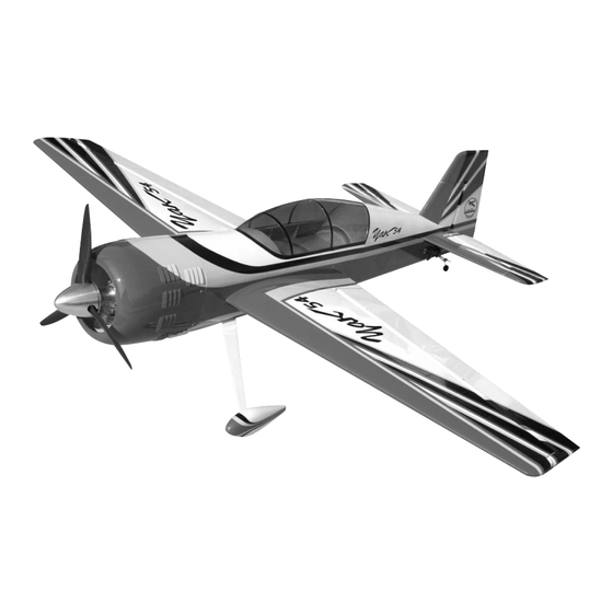
- Page 2 Congratulations on your purchase of the 87” Before beginning assembly of your 87” Yak 54 Yak 54 ARF. Every effort has been made to ARF, we highly recommend that you study this produce a lightweight, straight, easy to assem- manual in its entirety. You should begin planning ble aircraft.
- Page 3 ADHESIVES & GLUING TECHNIQUES ITEMS NEEDED TO COMPLETE THIS AIRCRAFT CA adhesives are specially formulated to firmly glue the 24” Gasoline fuel Line plywood, hardwood, and balsa used in your model and to 20 to 24 oz Gasoline fuel tank withstand the vibration and stresses of high performance flight.
-
Page 4: Wing Assembly
WING ASSEMBLY Select the aileron for the wing half on which AILERON INSTALLATION you are working. Collect the following parts: Mix up a liberal amount of 30 minute epoxy. (1) Left wing Working with 1 hinge at a time, place a dab of (1) Right wing epoxy and insert the hinge half way into one of (1) Left aileron... -
Page 5: Aileron Control Horn Installation
Attach the 18” servo extension to the outer Pull the second servo wire out of the wing root servo. rib. Plug the two aileron servos into a “Y” harness. IMPO RTANT! To ensure that any connections locat- Always tape them securely together with ed inside the wing will not come loose, either when electrical tape. - Page 6 With the aileron servo in place, make a mark Thread the 4-40 x 3-1/4” double threaded rod on the aileron at a 90º degree angle to the into the nylon adjustable control horn. trailing edge and in line with the servo. Look Place a 4-40 hex nut and a metal clevis on the for the control horn hard point under the cov- other end of the threaded rod.
-
Page 7: Tail Wheel Assembly
MOUNTING STABILIZERS TAIL WHEEL ASSEMBLY Collect the following items (2) Stabilizers (4) 4-40 x 1/2” Button Head Bolts (1) Short Front Stabilizer Tube (1) Long Rear Stabilizer Tube Locate the two holes under the stabilizer tubes in the fuselage. Collect the following items Remove the covering over both screw holes. -
Page 8: Tail Wheel
TAIL WHEEL Collect the following items (1) Tail wheel bracket (2) #4 x 3/4” philip head screws (1) Small tail wheel (2) Wheel collars with set screws Thread the two threaded rods in to the brass axle. Note: Use thread lock on the set screw. Draw a centerline on the bottom of the fuse- lage where the tail wheel bracket will mount. - Page 9 HINGING RUDDER Collect the following items (1) Rudder (4) Hinges (1) 6-32 x 3” All Threaded Rod (2) 6-32 Locking Hex Nuts (2) #6 Washer (2) Nylon Adjustable Control Horn (2) Nylon Adjustable Horn Bracket Place on both ends of the threaded rod a Nylon Adjustable Control Horn.
-
Page 10: Hinging The Elevators
HINGING THE ELEVATORS Collect the following items: (2) Elevators (8) Hinges Thread the 4-40 pushrod into the nylon adjustable control horn Thread the 4-40 hex nut and the 4-40 metal clevis onto the other end of the pushrod. Connect the clevis to the servo arm. Place the clevis clip onto the clevis. - Page 11 HINT: Drill the hole from the bottom half way. WHEEL AND WHEEL PANTS Then measure and mark the top of the aileron and drill down to the hole from the Collect the following items: top of the aileron. (2) 5-32 x 1-1/4” Axle with Locking Nut Insert the 6-32 x 3”...
-
Page 12: Engine Installation
Landing Gear Wheel Pant Wheel Collars Wheel Mount the wheel pants back on the landing gear along with the wheel collars and wheels. Center the wheel on the axle. You will find both the horizontal and vertical lines marked on the firewall. ENGINE INSTALLATION The vertical line is off set to compensate for the 2 degrees right thrust. - Page 13 Remove for carbu- retor breathing The ignition box was mounted below where the fuel tank will be placed. FUEL TANK Note: The fuel tank must be designed for gas if you are using a DA50. The motor we used was mounted on pillars off of the firewall the proper distance (6-1/4”...
-
Page 14: Engine Throttle Installation
ENGINE THROTTLE INSTALLATION COWL INSTALLATION Collect the following items: Collect the following items: (1) 1/8” x 16” nylon tubing (1) Cowl (1) .072 x 18” Threaded Rod (4) 4-40 x 3/4” Button Head Socket Bolt (1) EZ connector (4) 1/4 x 1/4 Silicone tubes (1) Snap Nut You will have to remove any parts of the (1) 4-40 x 1/8 Screw... - Page 15 Drill a hole 7/64” through the cowl at the sec- WING BOLTS ond mark. Gather the following items Repeat step 4 for the remaining cowl mount- (1) Right & Left Wing Panels ing holes. (2) 1/4-20 x 1-1/4” Nylon Bolt (1) Wing Tube Caution: Always use thread lock on any bolt...
- Page 16 Balancing Balance the Yak 54 6-7/8 to 7-1/4 back from the leading edge next to the fuselage. For extreme 3D flying you may want to move the CG back even farther after you are familiar with the way the Yak 54 flies. Just remember that the further back you go the more sensitive it will become.