Table of Contents
Advertisement
Quick Links
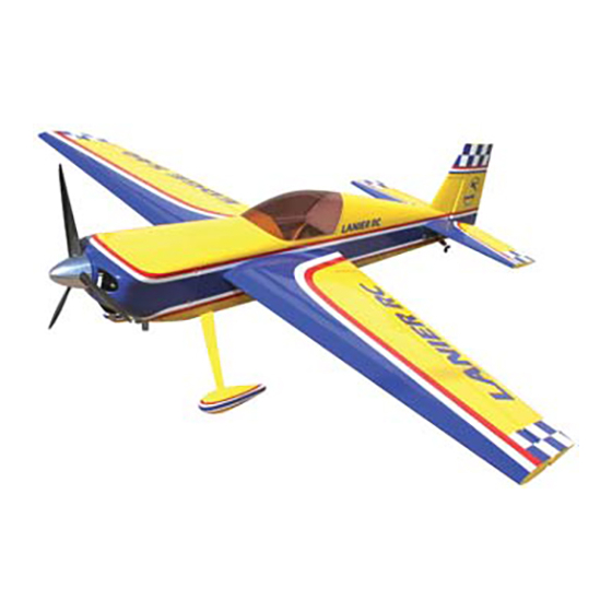
94" Edge 540
94" Edge 540
A radio-controlled model is not a toy and is not intended for persons under 16 years old. Keep
this kit out of the reach of younger children, as it contains parts that could be dangerous. A radio-
controlled model is capable of causing serious bodily injury and property damage. It is the buyer's
responsibility to assemble this aircraft correctly and to properly install the motor, radio, and all other
equipment. Test and fly the finished model only in the presence and with the assistance of another
experienced R/C flyer. The model must always be operated and flown using great care and common
sense, as well as in accordance with the Safety Code of the Academy of Model Aeronautics (5151
Memorial Drive, Muncie, IN 47302, 1-800-435-9262). We suggest you join the AMA and become prop-
erly insured prior to flying this model. Also, consult with the AMA or your local hobby dealer to find an
experienced instructor in your area. Per the Federal Communications Commission, you are required
to use only those radio frequencies specified "for Model Aircraft."
Lanier RC has inspected and certified the components of this aircraft. The company urges the buyer to perform his own inspec-
tion, prior to assembly, and to immediately request a replacement of any parts he believes to be defective for their intended use.
The company warrants replacement of any such components, provided the buyer requests such replacement within a period of 90
days from the date of purchase and provided the defective part is returned, if so requested by the company.
No other warranty, expressed or implied, is made by the company with respect to this kit. The buyer acknowledges and under-
stands that it is his responsibility to carefully assemble the finished flying model airplane and to fly it safely. The buyer hereby
assumes full responsibility for the risk and all liability for personal or property damage or injury arising out of the buyer's use of the
components of this kit.
Lanier R/C, INC. P.O. Box 458 Oakwood, Ga. 30566 PH 770 532 6401
WARNING
LIMITED WARRANTY
© copyright 2006 Lanier R/C
ARF
ARF
Advertisement
Table of Contents

Related Manuals for Lanier R/C 94” Edge 540 ARF


Summary of Contents for Lanier R/C 94” Edge 540 ARF
- Page 1 Lanier R/C, INC. P.O. Box 458 Oakwood, Ga. 30566 PH 770 532 6401 © copyright 2006 Lanier R/C...
- Page 2 Congratulations on your purchase of the 94” Before beginning assembly of your 94” Edge Edge 540 ARF. Every effort has been made to 540 ARF, we highly recommend that you study produce a lightweight, straight, easy to assem- this manual in its entirety. You should begin ble aircraft.
- Page 3 ADHESIVES & GLUING TECHNIQUES ITEMS NEEDED TO COMPLETE THIS AIRCRAFT CA adhesives are specially formulated to firmly glue the 24” Gasoline fuel Line plywood, hardwood, and balsa used in your model and to Engine (80cc) withstand the vibration and stresses of high performance flight.
-
Page 4: Wing Assembly
WING ASSEMBLY Select the aileron for the wing half on which AILERON INSTALLATION you are working. Collect the following parts: Mix up a liberal amount of 30 minute epoxy. (1) Left wing Working with 1 hinge at a time, place a dab of (1) Right wing epoxy and insert the hinge half way into one of (1) Left aileron... - Page 5 Attach the 18” servo extension to the outer Pull the second servo wire out of the wing root servo. rib. Plug the two aileron servos into a “Y” harness. IMPO RTANT! To ensure that any connections locat- Always tape them securely together with ed inside the wing will not come loose, either when electrical tape.
- Page 6 Adjustable horn bracket Pushrod coupler Pivot Pin E Clip 8-32 Nut With the aileron servo in place, make a mark on the aileron at a 90º degree angle to the 8-32 x 3” Hardened Bolt trailing edge and in line with the servo. Look for the control horn hard point under the cov- ering.
-
Page 7: Tail Wheel
Collect the following items (1) Tail wheel bracket (2) #4 x 3/4” philip head screws (1) Small tail wheel (2) Wheel collars with set screws Insert the pushrod coupler into the adjustable horn bracket Draw a centerline on the bottom of the fuse- Slide the pivot pin into the adjustable horn lage where the tail wheel bracket will mount. - Page 8 Trial fit the rudder on the fin and make sure all the hinges go in properly.Make sure that the top of the rudder will not rub on the top of the fin. Mark the location of the rudder control horn on the rudder by drawing a line from the bottom edge of the servo straight back to the rudder.
- Page 9 Locate the two holes under the stabilizer tubes in the fuselage. Remove the covering over both screw holes. Slide the short stabilizer tube into the front hole in the fuselage. Insert the long stabilizer tube in the rear hole of the fuselage. Using the 4-40 x 1/2”...
- Page 10 Locate the servo holes at the rear of the fuse- lage side. Remove the covering over both servo holes. Remove the covering over the servo holes on the other side of the fuselage Using the 24” servo extensions install the ele- vator servos facing the front of the plane as shown in the photo above.
-
Page 11: Hinging The Elevators
Landing Gear WHEEL AND WHEEL PANTS Wheel Pant ollect the following items: Wheel Collars (4) 5/32 Wheel Collars (2) 4-40 Blind Nuts (2) 4-40 x 1/2” Button Head Screws (2) 3-1/4” Wheels Wheel Mount the wheel pants back on the landing gear along with the wheel collars and wheels. -
Page 12: Engine Installation
Insert the hinges into the hinge hole in the sta- Assemble the pushrod connectors for the ele- vators on the output arms of the elevator ser- bilizers and the elevators vos as we did with the ailerons and rudder. Make sure that the hinges fits completely into the stabilizer and the elevator. - Page 13 Remove for carbu- retor breathing The motor we used (ZDZ80) required only a couple of washer to be at the proper length. We also had to open the fuel tank hole in the firewall to allow the rear mounted carb to extend into the motor box in the rear.
- Page 14 Assemble the cap with the vent line bent to fit to the top of the tank and the clunk where it is 1/4” off the bottom of the tank when held ver- tical. It is a good idea to use cable ties on the fuel lines to prevent them from coming off.(cable ties not included).
-
Page 15: Engine Throttle Installation
Mount the servo in the tray. Use the velcro to strap the tank to the plat- form. Connect the fuel lines from the tank to the engine. Attach the ez connector to your throttle output ENGINE THROTTLE INSTALLATION arm. Collect the following items: (1) 1/8”... - Page 16 WING BOLTS Gather the following items (1) Right & Left Wing Panels (2) 1/4-20 x 1-1/4” Nylon Bolt (1) Wing Tube Slide the wing tube into one of the wing halves. Cut four scraps of paper and tape to the side Slide the tube thru the fuselage.
- Page 17 RECEIVER, BATTERY & SWITCH 3/8” square sticks are provided with notches A mount for the receiver is supplied just in the fuselage sides which can be used for behind the wing tube. battery mounts if required, if not leave them out.