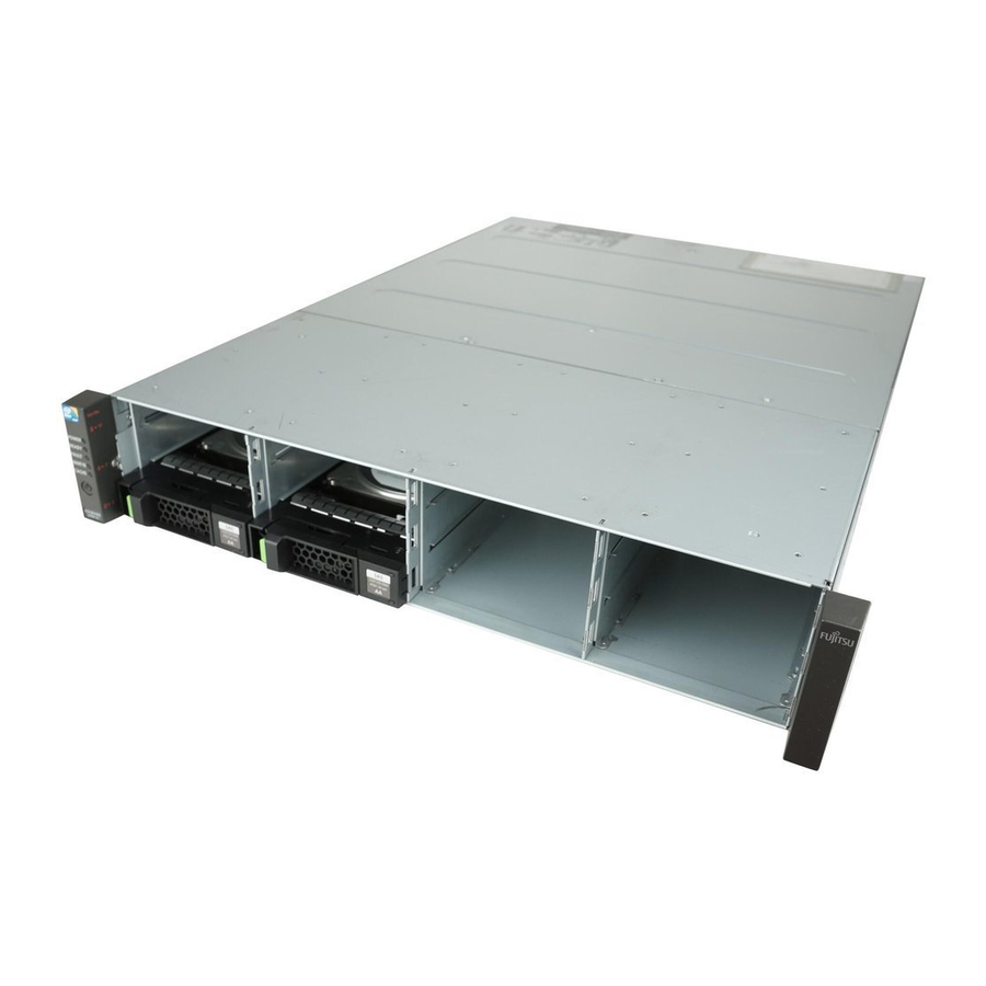
Fujitsu Eternus DX80 S2 Hardware Installation
Hide thumbs
Also See for Eternus DX80 S2:
- Cli user's manual (756 pages) ,
- User manual (186 pages) ,
- User's manual & installation instructions (147 pages)
Summary of Contents for Fujitsu Eternus DX80 S2
-
Page 1: Hardware Installation
ETERNUS DX80 S2 and DX90 S2 Hardware Installation Hardware Installation ETERNUS DX80 S2 and DX90 S2 Copyright Fujitsu Technology Solutions, Release August 2011... - Page 2 Package Contents Rack Mounting Power Cabling Backend Cabling QSFP Power On Procedure Power Off Procedures Operator Panel - Function Button Hardware Installation ETERNUS DX80 S2 and DX90 S2 Copyright Fujitsu Technology Solutions, Release August 2011...
-
Page 3: Package Contents
Single Controller Module • Dual Controller Module Left and right Flange Cover Push pin tool 2 x power cords Safety Manual Hardware Installation ETERNUS DX80 S2 and DX90 S2 Copyright Fujitsu Technology Solutions, Release August 2011... - Page 4 2 x power cords 1 x QSFP (SAS) cable • Single IOM configuration 2 x QSFP (SAS) cables • Dual IOM configuration Safety Manual Hardware Installation ETERNUS DX80 S2 and DX90 S2 Copyright Fujitsu Technology Solutions, Release August 2011...
-
Page 5: Rack Mounting
Rack Mounting (1) For FTS (CEMEA &I) only Rack-mount kit Rack mount installation overview Hardware Installation ETERNUS DX80 S2 and DX90 S2 Copyright Fujitsu Technology Solutions, Release August 2011... - Page 6 Insert the pins of the left hand side slide rail in the 1st and 3rd hole Start counting from the bottom of the 2U Bracket Hardware Installation ETERNUS DX80 S2 and DX90 S2 Copyright Fujitsu Technology Solutions, Release August 2011...
- Page 7 The M5 centering screws The M5 pan head screws M5 Centering screw (10 mm) M5 Pan head screw (10 mm) Hardware Installation ETERNUS DX80 S2 and DX90 S2 Copyright Fujitsu Technology Solutions, Release August 2011...
- Page 8 M5 Centering screw (10 mm) Base line of the Controller Enclosure M5 Cage nut M5 Pan head Base line of the screw (10 mm) Controller Enclosure Hardware Installation ETERNUS DX80 S2 and DX90 S2 Copyright Fujitsu Technology Solutions, Release August 2011...
- Page 9 Rack Mounting (5) Front view of the rack installation Hardware Installation ETERNUS DX80 S2 and DX90 S2 Copyright Fujitsu Technology Solutions, Release August 2011...
- Page 10 Fit the Controller Enclosure and/or Drive Enclosure to the rack For better stability, a rack has to be filled by starting from the bottom Hardware Installation ETERNUS DX80 S2 and DX90 S2 Copyright Fujitsu Technology Solutions, Release August 2011...
-
Page 11: Power Cabling
Connect each Power Supply of an Enclosure to different Power Distribution Units Always follow the local power cabling regulations! PSU#0 inlet PSU#1 inlet Hardware Installation ETERNUS DX80 S2 and DX90 S2 Copyright Fujitsu Technology Solutions, Release August 2011... - Page 12 Connect SAS (OUT) ports and SAS (IN) ports by daisy-chain Start in ascending order from the Controller Enclosure Drive Enclosure# 02 Drive Enclosure #01 Controller Enclosure Hardware Installation ETERNUS DX80 S2 and DX90 S2 Copyright Fujitsu Technology Solutions, Release August 2011...
- Page 13 SAS ports of the Controller Enclosure always have the type "OUT" Cable symbol Connect with Connect with the port where the port where is indicated is indicated Hardware Installation ETERNUS DX80 S2 and DX90 S2 Copyright Fujitsu Technology Solutions, Release August 2011...
- Page 14 Backend Cabling QSFP (3) QSFP connection between racks To connect QSFP cable between two racks an expansion cable of 3 or 6 meters is used Hardware Installation ETERNUS DX80 S2 and DX90 S2 Copyright Fujitsu Technology Solutions, Release August 2011...
-
Page 15: Single / Dual Controller Update
CM #0 CM#0 CM#1 IOM6 IOM6 IOM6 IOM6 IOM6 IOM6 CA: Channel Adapter IOM: IO module 1 CM to 2 CM upgrade parts DE: Device Enclosure Hardware Installation ETERNUS DX80 S2 and DX90 S2 Copyright Fujitsu Technology Solutions, Release August 2011... -
Page 16: Power On Procedure
If everything is OK, the green Ready LED in the CE and the green Power LED in the DE switch on Power O Fault Active O Power Ready Fault Maint/ID O Cache Hardware Installation ETERNUS DX80 S2 and DX90 S2 Copyright Fujitsu Technology Solutions, Release August 2011... - Page 17 CLI CACHE LED Constant green when data exists in cache memory Blinks in green when cached data is saved to the flash memory Hardware Installation ETERNUS DX80 S2 and DX90 S2 Copyright Fujitsu Technology Solutions, Release August 2011...
- Page 18 The Drive Enclosure is operating normally DE-ID (7-segment) Shows a 2-digit Drive Enclosure ID 2.5" Drive Ecnlosure Is assigned automatically by the SAS backend cabling 3.5" Drive Ecnlosure Hardware Installation ETERNUS DX80 S2 and DX90 S2 Copyright Fujitsu Technology Solutions, Release August 2011...
-
Page 19: Power Off Procedure
AC power cords from the PDUs after the system is powered off Make sure the CACHE LED of the Controller Enclosure is off Hardware Installation ETERNUS DX80 S2 and DX90 S2 Copyright Fujitsu Technology Solutions, Release August 2011... - Page 20 The Function Button is located next to the Power Switch 2.5" Controller Enclosure 3.5" Controller Enclosure Function Button Use the pin tool to operate Power Button Hardware Installation ETERNUS DX80 S2 and DX90 S2 Copyright Fujitsu Technology Solutions, Release August 2011...
- Page 21 Reset the LAN ports of the CM to the default values • Push down the Function Button three times within three seconds • The MAINT/ID LED blinks green for a few seconds Hardware Installation ETERNUS DX80 S2 and DX90 S2 Copyright Fujitsu Technology Solutions, Release August 2011...


