Table of Contents
Advertisement
Advertisement
Table of Contents

Related Manuals for WaterLogic WL4 Firewall


Summary of Contents for WaterLogic WL4 Firewall
- Page 1 WL4 Firewall Technical Manual...
- Page 2 Electrical Wiring Diagram 230V - Cold Only Wetted Parts Illustration - Hot, Cold and Sparkling Wetted Parts List- Hot, Cold and Sparkling Main Parts Illustration - Exploded View Main Parts List PCB Programming Procedure Waterlogic 4 Firewall Technical Manual - Issue A, October 2010...
-
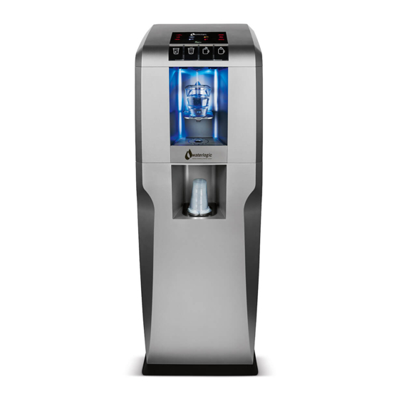
Page 3: Machine Overview
FILTERS concern the unit installed. The filtration system on the WL4 Firewall is designed to reduce dirt and sediment particles from the water. Furthermore, the Activated Carbon process will remove a whole range of contaminants e.g. chlorine and pesticides. It is important for the UV sterilization system to be supplied with clean water in order to achieve maximum efficiency. - Page 4 CO2 Cylinder & Gas Regulator: The units with the option of sparkling water will The PCB (Printed Circuit Board) is the control unit for the WL4 Firewall, it is need CO2 gas, food grade carbon dioxide. This gas is stored in cylinders in a liquid responsible for the functions of all the mechanical and electrical parts (24V DC).
- Page 5 TANK TANK FILTER DRYER FILTER DRYER COMPRESSOR SOLENOID VALVE 4 COMPRESSOR FAN MOTOR DRAIN DRAIN DRAIN FAN MOTOR VALVE VALVE VALVE DRAIN DRAIN DRAIN VALVE VALVE VALVE CHECK VALVE PUMP Waterlogic 4 Firewall Technical Manual - Issue A, October 2010...
- Page 6 COLD SPARKLING TANK CONDENSER TANK CONDENSER FILTER FILTER DRYER DRYER COMPRESSOR SOLENOID COMPRESSOR VALVE 4 FAN MOTOR FAN MOTOR DRAIN DRAIN DRAIN DRAIN VALVE VALVE VALVE VALVE CHECK VALVE PUMP Waterlogic 4 Firewall Technical Manual - Issue A, October 2010...
-
Page 7: Carbonation Tank
CAuTIONS: Only competent trained technicians should work on Waterlogic products. Waterlogic units may weigh over 25KG. We recommend caution when lifting. Packing materials could present a trip hazard. Keep them off the floor. Take care not to allow the power lead to get wet. If the lead gets wet it must not be used. -
Page 8: Installation Procedures
3 bar. 2. Mount the WL4 Firewall on a firm flat surface so that it cannot topple or fall from a 8. Connect to a CO2 regulator via a 1/4” John Guest tube and set to 3 bar. - Page 9 8. Check the electrical wall socket (polarity) and then make the electrical connec- REMOVING THE EMPTY CO2 BOTTLE tion to the WL4 Firewall by plugging the power lead in to the socket on the rear of Turn off the empty bottle and disconnect from gas regulator.
-
Page 10: Installation Kit
, the WL4 Firewall has entered sleep mode, pushing any button will bring the WL4 Firewall out of sleep mode. Sleep mode is an energy saving feature • The WL4 Firewall must be installed according to the local guidelines. -
Page 11: Maintenance And Servicing
Press and hold the hot water and extra hot water buttons together the WL4 Firewall’s upper metal shelf. Grip the 1st filter on the left and twist it clock for 3 seconds (This safety feature prevents hot water from being wise to release it. -
Page 12: Sanitising Or Descaling
Chlorine test strips. Flush the hot tank to ensure it is full of water and then turn on the green switch at the rear of the WL4 Firewall. The unit will now heat and cool. 10.The above method can be used to remove calcium from the hot tank by using a non toxic de-scale solution or powder (citric acid based) and flushing the hot water 15. -
Page 13: Advisory Icons
1. No flow of water: Ensure that there is a water supply to the WL4 Firewall from the building and that the installation isolation valve is turned on. If the installation kit has an anti-leak device included in it (as Waterlogic Installation kit) then make sure it has not tripped. -
Page 14: Technical Specifications And Warranties
• Incorrect installation for more than 5 minutes continuously. • Incorrect use of the WL4 Firewall 8. Bad or plastic taste: If the WL4 Firewall is new it may need flushing for a longer • Unsuitable electrical and water supply period. - Page 15 114W 114W 114W 114W ROHS Pump All Waterlogic machines comply with EC Directive (2002/95/EC) on the Restriction UV Lamp of the Use of Certain Hazardous Substances in Electrical and Electrical Equipment Control Units (RoHS). Unit Total 668W 656W 168W 156W 156W 168W 656W 156W 156W BIOCOTE®...
-
Page 16: Electrical Wiring Diagram 230V
Drip tray sensor Thermistor (over-heat) Hot water heater UV lamp DANGER HIGH VOLTAGES PRESENT ON THIS PCB Hot water level check Water leak sensor CARE MUST BE TAKEN WHEN LIVE TESTING Waterlogic 4 Firewall Technical Manual - Issue A, October 2010... - Page 17 Thermistor (cold water) Drip tray sensor UV lamp Drip tray sensor Thermistor (over-heat) Motor for compressor Water leak sensor Hot water heater UV lamp Hot water level check Water leak sensor Waterlogic 4 Firewall Technical Manual - Issue A, October 2010...
-
Page 18: Wetted Parts Illustration
Sparkling water level check BT PCB Ballast PCB Thermistor (cold water) UV sensor Thermistor (over-heat) Drip tray sensor UV lamp Motor for compressor Water leak sensor Fan motor for compressor Waterlogic 4 Firewall Technical Manual - Issue A, October 2010... -
Page 19: Wetted Parts List
PU-4031 JG LLD PE Tube - Blue O.D.1/4" PU-4064 Silicon Tube 5/16" for hot water Air Vent 460mm PU-4011 JG Equal Tee Connector 1/4" (PI0208S) PU-4016 Solenoid Valve DC24V 1000mm Waterlogic 4 Firewall Technical Manual - Issue A, October 2010... - Page 20 PL-1327 WL-4 Mini Side Panel-R ST-8286 WL4 Micro SW metal cover PL-1329 WL-4 Safety Micro Switch Cover EL-5027 Micro Door Lock S/W only CO-9001 Compressor (R134a 1/8HP) 230V/50Hz thermally protected Waterlogic 4 Firewall Technical Manual - Issue A, October 2010...
- Page 21 WL-4 Omnipure filter fixing bracket FU-0001-A WL4Firewall -Al Housing CU-0001 Cushion for solenoid valve ST-8298 WL4 Firewall system fixing bracket to the upper shelf CT-2036-B Water level sensor PL-1337 WL-4 LCD Cover Panel(WL Logo) PU-4008 JG Equal Elbow Connector 1/4" (PI0308S)
-
Page 22: Button Descriptions
PCB Programming Procedure Service Pcb Kits The service PCB has been developed to allow the WL4 4 Firewall PCB to be reset using an external pcb. BuTTON DESCRIPTIONS uP: Menu Up DOWN: Menu Down ENTER: Enter and Modify SELECT: Select and Enter/Exit READ/SEND: Read/Send Data Service PCB RS232... - Page 23 • Press any one of the three buttons - Up, Down or Enter, the screen will show o read back from the top setting. Sending. This shows the Service PCB is communicating with the WL4 FIREWALL to read Note: At this stage, the Service PCB can read the actual settings and cannot its actual data.
- Page 24 Now press the “Enter” button and the display will change to the first setting menu SET °C/°F: °C or °F”. • To send the new setting data to the WL4 FIREWALL PCB, press the “ Select” button, the screen will display SEND WORK DATA and SEND LED will be illuminated.
- Page 25 Speak to a Water Expert uSA, Canada and Mexico exportsales@waterlogic.com info@waterlogicusa.com + 353 1 293 1960 + 1 402 884 7212 WLI Trading Ltd. Waterlogic uSA, 4141 N. 156th Street, Suite 4, 2nd Floor Beacon Court, Omaha, NE 68116 Sandyford, Dublin 18, Ireland www.waterlogic.com...