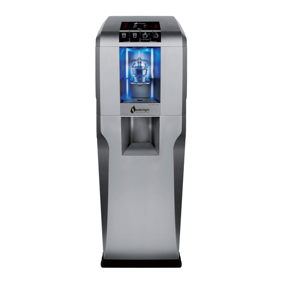
WaterLogic WL400 Installation Procedures Manual
Hide thumbs
Also See for WL400:
- Manual (84 pages) ,
- Operating, installation and service manual (73 pages) ,
- Service manual (31 pages)
Advertisement
Quick Links
DANGER! ELECTRICAL SHOCK HAZARD.
Only qualified personnel who have read and understand this entire manual should attempt to
install, or service this unit, failure to do so could result in death or serious injury.
WARNING! ALWAYS SANITIZE BEFORE USE.
Sanitize before use to eliminate any potential microbiological contaminates.
Green Compressor/Heater Switch must be in the O=OFF position while the Hot
Tank is empty. Damage could occur within one minute and the two Hot Tank
Overload Devices (High Safety Limit) require manual reset if heater is turned on
with an empty Hot Tank.
CAUTION! DRIP TRAY DRAIN.
If you intend to provide a drip tray drain for your customer, be aware that you
will be called multiple times per month to service and unclog the tubing leading
away from the drip tray to drain. Users will clog the drain with paper clips,
erasers, napkins, tea bags, gum, and various other intended items. Waterlogic
recommends you establish a minimum of weekly visits to the machine for
cleaning of the drip tray drain.
Sanitization of Machine
Materials Needed:
Personal Protective Equipment. Rubber or Nitrile Safety Gloves and Protective Eyewear
Phillips Screwdriver
Temperature Gauge
Water Pitcher or Container to collect water from the faucet
5‐gallon container or drain basin
Sanitizer ‐ Household Bleach (5.25% Sodium Hypochlorite) or Citric Acid Based Cleaner
¼" Plastic Tubing, at least 4 feet in length, and assorted ¼" quick connect fittings
TDS Meter and Test Strips for measuring chlorine – Optional
Sanitizing Cartridge
1. Unpack the Waterlogic WL400 and check exterior for damage.
Sanitize using a Household Bleach (5.25% Sodium Hypochlorite solution) or other approved
cleaner throughout the cold and sparkling water circuits. Follow all instructions on the sanitizer
and flush with fresh water through the faucet until odor and taste is acceptable.
WARNING! USE PROPER PERSONAL PROTECTIVE EQUIPMENT
Always ensure proper ventilation and use proper personal protective equipment such as gloves
and eye protection when using chemicals. Refer to Material Safety Data Sheet for specific
requirements of each chemical product. Take all necessary precautions to prevent sanitizer from
contacting eyes, clothing, and any other surfaces in could damage (carpets).
WL400 Manual Page 49 – Revision: 7‐16‐2018
PRE‐INSTALLATION PROCEDURES
Advertisement

Related Manuals for WaterLogic WL400


Summary of Contents for WaterLogic WL400
- Page 1 Sanitization of Machine Materials Needed: Personal Protective Equipment. Rubber or Nitrile Safety Gloves and Protective Eyewear Phillips Screwdriver Temperature Gauge Water Pitcher or Container to collect water from the faucet 5‐gallon container or drain basin Sanitizer ‐ Household Bleach (5.25% Sodium Hypochlorite) or Citric Acid Based Cleaner ¼” Plastic Tubing, at least 4 feet in length, and assorted ¼” quick connect fittings TDS Meter and Test Strips for measuring chlorine – Optional Sanitizing Cartridge 1. Unpack the Waterlogic WL400 and check exterior for damage. Sanitize using a Household Bleach (5.25% Sodium Hypochlorite solution) or other approved cleaner throughout the cold and sparkling water circuits. Follow all instructions on the sanitizer and flush with fresh water through the faucet until odor and taste is acceptable. WARNING! USE PROPER PERSONAL PROTECTIVE EQUIPMENT Always ensure proper ventilation and use proper personal protective equipment such as gloves and eye protection when using chemicals. Refer to Material Safety Data Sheet for specific requirements of each chemical product. Take all necessary precautions to prevent sanitizer from contacting eyes, clothing, and any other surfaces in could damage (carpets). WL400 Manual Page 49 – Revision: 7‐16‐2018 ...
- Page 2 2. Put 1 teaspoon of sanitizer per directions or use Bleach Solution (1 teaspoon = 1/6 oz. = 5 ml = ½ cap full) of household bleach (Sodium Hypochlorite 5 ‐ 10% Concentration) in the Sanitizing Cartridge. Always ensure sanitizer is compatible with stainless steel and acetyl plastic. 3. Connect sanitizing cartridge to inlet water supply and connect to inlet bulkhead fitting on back of unit. Turn on water supply. 4. Connect power to WL400 Water Treatment System. Turn on Red Power Switch. DO NOT TURN ON GREEN HEATER/COMPRESSOR SWITCH AT THIS TIME. CAUTION! NEVER TURN ON HEATER BEFORE FILLING HOT TANK. Green Heater/Compressor Switch must be in the O=OFF position while the hot tank is empty. Damage could occur within one minute and the overloads (high limit) will require manual reset if heater is turned on with an empty hot tank. Fill the Cold Circuit with Sanitizer 5. Depress the Main Dispensing Button on the Front Control Panel until cold water/sanitizing solution comes out the faucet. NOTE: Container and drain basin will be required to catch the water from the faucet. WARNING! Use Personal Protective Equipment. Gloves and Eye Protection Required. The first 2 or 3 gallons of water will contain concentrated sanitizer. Use extreme care! 6. Turn off water supply and remove Sanitizing Cartridge from inlet water supply. Reconnect water supply to Inlet Bulkhead Fitting. Flushing the Sanitizer from the Machine 7. Flush thoroughly per filter manufacturers’ recommendation with fresh water to drain. ...
- Page 3 10. CAUTION! NEVER TURN ON HEATER BEFORE FILLING HOT TANK. Green Heater/Compressor Switch must be in the O=OFF position while the hot tank is empty. Damage could occur within one minute and the overloads (high limit) will require manual reset if heater is turned on with an empty hot tank. 11. Remove Front Panel from Base Cabinet opening Top of Panel and Removing Slide Bar. 12. Attach WL400 Water Treatment System to Base Cabinet with Locking Bolt provided. 13. Connect wires (quick connect clips) on back of unit from Base Cabinet to WL400 Water Treatment System. 14. Remove Pre‐Carbon and Post Carbon filters and flush 5 gallons of water through each filter separately. 15. Reinstall Pre and Post Carbon Filters. 16. Close RO bypass and bladder tank. Bladder Tank RO Bypass WL400 Manual Page 51 – Revision: 7‐16‐2018 ...
- Page 4 17. On Back of Cabinet, connect two pieces of tubing to the RO Drain and Water Out line and run to external drain. 18. Connect power cord to WL400 Water Treatment System and turn on Red Power Switch. 19. Connect power to WL400 Water Treatment System. Turn on Red Power Switch I=ON. DO NOT TURN ON THE GREEN HEATER/COMPRESSOR SWITCH CAUTION! NEVER TURN ON HEATER BEFORE FILLING HOT TANK. Green Heater/Compressor Switch must be in the O=OFF position while the hot tank is empty. Damage could occur within one minute and the overloads (high limit) will require manual reset if heater is turned on with an empty hot tank. 20. Connect supply water to Water In Fitting on back of cabinet. Turn on water supply and flush RO system to drain for 4 hours. Water should be draining from both Water Out line and the Drain Line. 21. After 4 hours of flushing, turn Off Incoming Water. Connect water line from the Base Cabinet to Water In fitting on WL400 Water Treatment System. 22. Open Bladder Tank and turn on supply water. 23. Allow Bladder Tank to fill for 1 hour. 24. Fill Hot Tank for approximately 1 minute. Depress both the “Hot” and “Extra Hot” buttons to ...
- Page 5 Never look directly at an operating UV light. Disconnect wiring before removing. 28. Remove UV Firewall™ Lamp from Firewall™ housing. Remove Top Cover from Firewall™ housing. Carefully remove Quartz Sleeve Spiral from Firewall™ Housing and inspect for cracks or other damage. Reinsert Quartz Sleeve Spiral, replace top cover of housing. Inspect UV lamp and reinsert into Housing. 29. Press Dispensing Button and check for blue glow from top of Firewall™ Housing and at Faucet dispensing area to ensure UV lamp is operational. 30. Disconnect UV lamp to test UV lamp sensor operation. Unit should alarm and UV Icon on display will light. 31. Disconnect power to WL400 Water Treatment System. 32. Reconnect UV lamp. 33. Connect power to WL400 Water Treatment System. Compressor Test 34. Switch Green Heater/Compressor to on I=ON position. Always ensure tanks are full of water before turning on the heater or the overloads (high limit) will open and require manual reset. If the wire condenser at back of the unit is warm, the refrigeration system is working. 35. Once the WL400 Water Treatment System reaches its target temperature, the compressor will ...
- Page 6 36. Always ensure tanks are full of water before turning on the Heater or the Overload (High Limit) will open and require manual reset. It will take the heater approximately 10 minutes to heat the water from ambient 75°F (24°C) to the factory set point of 185°F (85°C). Dispense a cup of hot water to ensure the temperature/odor/taste is acceptable. WARNING! VERY HOT WATER CAN BURN OR SCALD. Hot water should be dispensed carefully into insulated container to avoid WL400 Manual Page 54 – Revision: 7‐16‐2018 ...
- Page 7 WL400 DRAINING INSTRUCTIONS Draining Notes Drain the WL400 Water Treatment System for transportation. WARNING! STORE UNIT EMPTY. ALWAYS SANITIZE BEFORE REUSE. The unit must be completely drained and sealed before storing to avoid stagnation and reduce microbial growth). Prior to draining the Hot Tank, turn Off the Green Compressor / Heater switch (O=OFF), and dispense 2 liters of hot water from the machine. As hot water is dispensed from the faucet of the unit, colder water will be introduced into the hot tank. Since Green Compressor / Heater switch is turned off, the heater will not energize and heat the incoming tap water. Following this precaution prevents exposing personnel and equipment (drains, catch basin, etc.) to scalding hot water. Disable Cold and Hot Tanks 1. Turn off the Green Heater / Compressor switch to disable the heater and compressor. 2. Dispense 1 liter of water through the hot tank to cool the water temperature in the hot tank and avoid burns. WARNING! WL400 Water Treatment System produces VERY HOT WATER up to 203°F (95°C). Water above 125°F (52°C) can cause severe burns or scalding. Hot water should be dispensed carefully into insulated container to avoid injury. Turn Off Water Supply and Bleed Water Pressure 3. Isolate the unit from feed water by turning off the supply. 4. Turn off Bladder Tank. ...
- Page 8 9. Disconnect Cold Line from top of Cold Tank. 10. Remove Drain Caps and Plug from Cold Water Tank Drain on the back of the WL400 Water Treatment System. 11. Open Bladder Tank. 12. After unit has finished draining, replace Plug and Drain Caps. 13. Reconnect tubing to Cold Tank. 14. Close lid, close locks and replace screws in Top Cover. WL400 Manual Page 56 – Revision: 7‐16‐2018 ...
- Page 9 BASE CABINET ASSEMBLY Insert the four corner supports into the base panel. Secure with one screw to the bottom of each upright. Place Top Panel on to the corner supports. Secure with two screws to the top of each upright. WL400 Manual Page 57 – Revision: 7‐16‐2018 ...
- Page 10 Fix the back panel into the base panel and secure with four screws. Fix the side panels into the base panel and secure with two screws in each through the top panel. WL400 Manual Page 58 – Revision: 7‐16‐2018 ...
- Page 11 Place the WL400 Counter Top onto the base cabinet. Secure as shown. Attach the door strap to the door using the three short screws. Align bottom of door into the base panel and attach door strap into cabinet housing. WL400 Manual Page 59 – Revision: 7‐16‐2018 ...
-
Page 12: Installation Procedures
WARNING! USE ONLY Waterlogic SUPPLIED POWER CORD. Locate system within 5 feet of power supply. Never use an extension cord or adapter. Do not use a damaged power cord or plug. Keep power cord out of heavy traffic areas and away from heat sources. Do not, under any circumstances, remove ground prong or alter the power cord. Never pull the power plug from the outlet with a wet hand or allow the plug to get wet. Failure to use the supplied power cord will void UL Certification and Warranty. CAUTION! INDOOR USE ONLY. Never expose to direct sunlight, heat sources, or ambient air temperature above 100°F (37°C) or below 35°F (2°C). Install indoors and keep unit away from excessive humidity. Never expose to freezing temperatures. Ensure there is adequate clearance around the unit to allow refrigeration system condenser to dissipate heat. Warmer environments require more clearance around the unit. Minimum clearance around all surfaces of the machine is 2‐ inches. Installs where the ambient temperature exceeds 80°F, require a minimum of 4‐inches clearance for proper heat dissipation and efficient operation. CAUTION! USE A WATER PRESSURE REGULATOR. Waterlogic will not be responsible for injury or damage caused by excessive water pressure. Operating pressure must be 40 psi to 60 psi. Be aware any of potential pressure surges caused by building/municipal pumping stations. CAUTION! USE UV STABILIZED SUPPLY LINES. Feed the unit with a potable ambient or cold water supply only. Feed water over 100° F (37°C) can damage the treatment components. Water block devices and external leak detectors are strongly recommended. Locate the unit as close to the water supply and the electrical connections as possible. WARNING! STORE AND TRANSPORT UNIT EMPTY. ALWAYS SANITIZE BEFORE USE. The unit must be completely drained and sealed before storing to avoid stagnation and reduce microbiological contamination (potential bacterial growth). Sanitize before use to eliminate any potential microbiological contaminates Pre‐installation and sanitization procedures as prescribed in this manual must be performed before installing the WL400 Water Treatment System Always install indoors and place the Waterlogic WL400 Water Treatment System on a firm, flat and stable surface. WL400 Manual Page 60 – Revision: 7‐16‐2018 ... - Page 13 1. Unpack the Waterlogic WL400 Water Treatment System and check exterior for damage. 2. Remove Front Panel from Base Cabinet opening Top of Panel and Removing Slide Bar. 3. Remove WL400 Water Treatment System from packaging and place on top of base cabinet. 4. Attach WL400 Water Treatment System to base cabinet with Locking Bolt provided. Remove Two Screws a) Remove screws from locking slides located under Front Cover adjacent to faucet. Slide Locks Open b) Unlock slides and open Top Cover of WL400 Water Treatment System. c) Pull cover forward and lift from the front to open top cover. d) Locate wires and run them through. 5. Connect Wires (Quick Connect Clips) on back of unit from Base Cabinet to WL400. ...
- Page 14 Green Heater/Compressor Switch must be in the O=OFF position while the hot tank is empty. Damage could occur within one minute and the overloads (high limit) will require manual reset if heater is turned on with an empty hot tank. 11. Connect supply water to water in fitting on back of cabinet. Turn on the Water Supply and flush RO system to drain for 4 hours. Water should be draining from both Water Out Line and Drain Lines. 12. After 4 hours, turn off Incoming Water. Connect Water Out Line from Base Cabinet to drain water in fitting on WL400 Water Treatment System. 13. Open Bladder Tank and turn on supply water. 14. Allow bladder tank to fill for 1 hour. 15. Fill Hot Tank (Approximately 1 minute). Depress both Hot and Extra Hot Buttons to dispense. Red light should illuminate above dispensing area after 2 second delay. 16. Fill Cold Tank (Approximately 2 minutes). Blue light should illuminate above dispensing area. 17. Turn on Green Heater/Compressor Switch. I=ON. ...