Table of Contents
Advertisement
Quick Links
Download this manual
See also:
Configuration Manual
Advertisement
Table of Contents

Related Manuals for Dell E1200i ExaScale


Summary of Contents for Dell E1200i ExaScale
- Page 1 E1200i ExaScale Installation Guide...
- Page 2 © 2010 Dell Force10. All rights reserved. Reproduction of these materials in any manner whatsoever without the written permission of Dell Inc. is strictly forbidden. Trademarks used in this text: Dell™, the DELL logo, Dell Precision™, OptiPlex™, Latitude™, PowerEdge™, PowerVault™, ®...
-
Page 3: Table Of Contents
Contents 1 About This Guide Information Symbols and Warnings ........7 Related Publications . - Page 4 9 Installing RPMs, Line Cards, and SFM3s Unpacking an RPM or Line Card ........43 Important Points to Remember .
-
Page 5: Contents
Removing and Replacing line cards or RPMs ......63 Removing and Replacing SFM3s ........64 Removing and Replacing the Air Filter . - Page 6 Contents...
-
Page 7: About This Guide
RPM, SFM3, and line card slots. Blanks are required in empty slots to ensure adequate system cooling and for EMI containment during operation. E1200i systems run Dell Force10 OS (FTOS™) software. After you complete the hardware installation Configuration Guide for software configuration... -
Page 8: Related Publications
WARNING: Leakage Current (High Touch Current) in AC-powered systems: AC power cords are secured to the power inlet using the provided brackets. The power cord plugs must be secured to the building outlets by the qualified chassis installer or a qualified electrician. Chapter 3, Site Preparation for more cautions. -
Page 9: The E1200 System
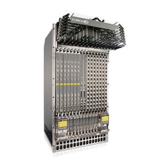
The E1200 System The Dell Force10 E1200 system is a carrier-class, high-capacity aggregation router. The 16-slot modular system provides two slots dedicated for Route Processor Modules (RPMs) and 14 slots for line cards with Layer 2 switching and Layer 3 and routing capabilities. - Page 10 Figure 2-1. E1200i AC Chassis Front View Cable Management System Line Card Slots RPMs Switch Fabric Modules (SFM3s) Blanks (BLNK) Air Filter Air Vents AC Power Supplies AC Power Plugs The E1200 System...
- Page 11 Figure 2-2. E1200 AC Chassis Rear View Locking Screw Installed Fan Tray Empty Fan Tray (with self-closing door) Ground Connection The E1200 System...
- Page 12 Figure 2-3. E1200i DC Chassis Front View Cable Management System Line Card Slots RPMs Switch Fabric Modules (SFM3s) DC Power Supply Air Filter Air Vents The E1200 System...
- Page 13 Figure 2-4. E1200 DC Chassis Rear View Locking Screw Installed Fan Tray Empty Fan Tray (with self-closing door) Ground Connection Table 2-1. E1200 Hardware Component Operating Requirements Summary Component Minimum Maximum Field-Replaceable Backplane (factory installed) Air filter (factory installed) Fan trays RPMs Line cards SFM3s...
- Page 14 To install the E1200 system: Step Task Section Prepare the site Site Preparation Unpack the AC chassis and components Unpacking the E1200 System Unpack the DC chassis and components Unpacking the E1200 System Mount the AC chassis Standard Front Chassis Mounting Installing the Chassis into an Equipment Cabinet Mount the DC chassis Standard Front Chassis Mounting...
-
Page 15: Site Preparation
Site Preparation This chapter describes factors to consider before installing your E1200 system. The following topics are discussed: • Site Selection Criteria • Rack Mounting • Cabinet Placement • Power • Fans and Airflow • Storing Components For complete E1200 System Specifications, refer to Chapter C, System Specifications. -
Page 16: Rack Mounting
• Ensure that the equipment is properly grounded. • Do not place objects on top of unit. CAUTION: The E1200 AC shipping containers each weigh up to 400 pounds. The unpacked chassis and pallet weigh approximately 200 pounds. Do not attempt to lift or move the chassis without the use of a hand cart, pallet jack, or forklift.Lift the E1200 chassis either from the bottom or by the handles provided with the front shipping cover. -
Page 17: Fans And Airflow
WARNING: The E1200i AC Chassis is shipped with two tool-accessible covers preventing access into the alternative DC PEM cavities. Do not remove these covers; they prevent unauthorized access to high direct current locations within the chassis. The covers must remain in place at all times. WARNING: Make your chassis ground connections first (see Figure 2-2). - Page 18 • Non-condensing relative humidity should be maintained within 5 to 95 percent. • Store on a dry floor, away from direct sunlight, heat, and air conditioning ducts. • Store in a dust-free environment. Site Preparation...
-
Page 19: Installing The Ac Chassis
Installing the AC Chassis This chapter provides instructions to rack mount your E1200 system into a standard 19-inch or 23-inch equipment rack. It contains the following sections: • Unpacking the E1200 System • Installing the Equipment Rack Shelf Bar • Standard Front Chassis Mounting •... -
Page 20: Installing The Equipment Rack Shelf Bar
Installing the Equipment Rack Shelf Bar The rack shelf bar (Figure 4-1) enables you to easily position the chassis into the rack and provides the unit additional stability. The E1200 system must be mounted in a rack that is permanently secured to the floor. - Page 21 • Sie die Einheit im Gestell anbringen oder sie warten. NOTE: Dell Force10 recommends that you install and operate the E1200 system in a standard 19-inch or 23- inch equipment rack. Install the E1200 system after you secure the equipment rack shelf bar. Load the chassis in the lower half...
-
Page 22: Installing The Chassis Into An Equipment Cabinet
Installing the Chassis into an Equipment Cabinet Install the E1200 system after you secure the rack shelf bar. Load the chassis in the lower half of the cabinet to avoid it becoming top-heavy. Make sure the cabinet is positioned with adequate space in the front, rear, and sides of the unit for proper ventilation, access to cables, and access for maintenance. -
Page 23: Installing The Dc Chassis
Installing the DC Chassis This chapter provides instructions to rack mount your E1200 system into a standard 19-inch or 23-inch equipment rack. It contains the following sections: • Unpacking the E1200 System • Standard Front Chassis Mounting • Installing the Chassis into an Equipment Cabinet Unpacking the E1200 System The E1200 DC system and components are shipped on a wooden pallet with Front Shipping cover. -
Page 24: Installing The Equipment Rack Shelf Bar
Installing the Equipment Rack Shelf Bar The rack shelf bar (Figure 5-1) enables you to easily position the chassis into the rack and provides the unit additional stability. The E1200 system must be mounted in a rack that is permanently secured to the floor. - Page 25 • Sie die Einheit im Gestell anbringen oder sie warten. NOTE: Dell Force10 recommends that you install and operate the E1200 system in a standard 19-inch or 23- inch equipment rack. Install the E1200 system after you secure the equipment rack shelf bar. Load the chassis in the lower half...
-
Page 26: Installing The Chassis Into An Equipment Cabinet
Installing the Chassis into an Equipment Cabinet Install the E1200 system after you secure the rack shelf bar. Load the chassis in the lower half of the cabinet to avoid it becoming top-heavy. Make sure the cabinet is positioned with adequate space in the front, rear, and sides of the unit for proper ventilation, access to cables, and access for maintenance. -
Page 27: Installing Fan Trays
Installing Fan Trays Access the fan tray slots from the rear of the chassis (Figure 6-1). Two fan trays are required in the chassis. When a fan tray is not installed in the lower slot, a self-closing door will seal the slot. Panel blanks are not required. - Page 28 Figure 6-2. Fan Tray screw latch Install the fan trays after the chassis is installed securely in the equipment rack. Access the fan tray slots from the rear side of the chassis. To ensure proper temperature and airflow control, all six fan trays must be installed before you supply power to the system.
-
Page 29: Installing Ac Power Supplies
Installing AC Power Supplies The E1200 system requires a minimum of 3 AC power supplies in a shelf (0, 1, 2 or 3, 4, 5) to operate. For full redundancy use 6 power supplies so that if one power supply fails in one shelf, the system remains operational operates with the 3 power supplies in the other shelf. -
Page 30: Securing The Chassis Ground
Power Cord Requirements If using a power cord other then a Dell Force10 supplied power cord, the cord must terminate at a right angle to the power module, see Figure 7-1. -
Page 31: Ac Power Supply And Fan Operability Test
• JAP: NEMA 6-20, L6-20, L6-30 • JAP 220: NEMA 6-20, L6-20 • US: C20 • US 220: NEMA 6-20, L6-20, L6-30 (30A) • CAUTION: The power cord is the main power disconnect device; ensure that the socket-outlet is located/ installed near the equipment and is easily accessible. - Page 32 • The AC-cord Retainer is secured over the plugs. WARNING: Prevent exposure and contact with hazardous voltages. Do not attempt to operate this system without the AC-cord Retainer. • Your power cables connect to an appropriate AC power supply in a manner that complies with your local electrical codes.
- Page 33 Power Supply and Fan Tray LEDs Table 7-1. Power Supply LEDs Status LED is ... No AC power Unlit: No connection Operational (On/Standby switch may be set to Standby) Lit: GREEN Power Supply Failure Lit: AMBER Table 7-2. Fan Tray LEDs Status LED is ...
- Page 34 Installing AC Power Supplies...
-
Page 35: Installing Dc Power Supplies
Installing DC Power Supplies The E1200 system requires a minimum of one DC Power Entry Module (PEM) to operate, but 2 are recommended for redundancy. To comply with safety agency and EMI regulations, you must install covers on all power supply slots not containing a PEM. Connect the PEMs to the appropriate branch circuit protection as defined by local electrical codes. -
Page 36: Cable And Connector Requirements
E1200 PEM studs. Installing DC PEMs CAUTION: Provide an easily accessible external disconnect. Dell Force10 recommends that you use a 150A circuit breaker. CAUTION: Un interrupteur externe doit être fournis et doit être facilement accessible. Dell Force10 recommande l'utilisation d'un disjoncteur de 150Ampères. - Page 37 Parameter Specifications Input Voltage -48 to -60 Vdc Use the following steps to install a DC PEM: Step Task Make sure that the remote power source (the circuit breaker panel) is in the OFF position. Make sure that the over-current protector (located on the PEM front panel) is in the OFF position. Loosen the retaining screw and remove the PEM safety cover.
- Page 38 Step Task (continued) Secure the chassis ground connection first: Remove one outer nut and one washer from each of the six studs. One nut should remain, tighten on the stud to 20 in/lbs. If the inner nut is loose, re-tighten it to 25 in/lbs. Locate the chassis ground connector studs on the PEM front panel (see Figure 8-3).
- Page 39 Step Task (continued) Route the terminated cables down and toward the rack rail, as shown below. Figure 8-5. Connecting the Ground Cable to the E1200 PEM Split-lock washer Lug nuts Ground studs Figure 8-6. DC PEM with Connections in Place Ground cable typically green -48 (-) cable...
-
Page 40: Dc Power Supply And Fan Operability Test
Step Task (continued) Replace the safety cover and tighten the captive screw with a #2 Phillips screwdriver (Figure 8-7). Figure 8-7. Reinstalling the PEM Safety Cover Check that the over-current protector (located on the PEM front panel) is in the OFF position. Energize the remote power source. - Page 41 • Two fan trays are installed. To test the power supplies and fan trays: Step Task With the fan trays and DC PEMs installed, power on the system. • Flip the over-current protector (located on the PEM front panel) to the ON position. Power Supply Status LEDs should be green.
- Page 42 Installing DC Power Supplies...
-
Page 43: Installing Rpms, Line Cards, And Sfm3S
Installing RPMs, Line Cards, and SFM3s This chapter provides instructions for installing cards into the E1200 AC or DC chassis. It contains the following sections: • Unpacking an RPM or Line Card • Installing Line Cards and RPMs • Preparing and Installing RPMs and Line Cards •... -
Page 44: Rpms
RPMs are designed to be installed in either the center R0 or R1 slots. Since FTOS searches for an RPM in slot 0 first, Dell Force10 recommends you install your RPM in slot 0 when only running with one RPM. Do not force RPMs into line card slots. RPMs are keyed differently than line cards to prevent improper installation. -
Page 45: Blank Panels
Figure 9-1. Line Card Numbering Port 0 Port 9 Blank Panels CAUTION: To avoid a chassis over-temperature condition, install blanks for RPMs, SFM3s, and line card slots not in use. Always replace cards or blanks immediately. Blank panels for RPMs, SFM3s, and line cards must be installed in empty slots to control airflow. If a slot is not filled a high-temperature condition might occur: %CHMGR-2-MINORTEMP: Minor alarm: chassis temperature high (SFM temperature reaches or exceeds threshold of 65C) - Page 46 Figure 9-2. Installing Cards into the E600 Figure 9-3. RPM and Line Card Slot Numbering Label Slot CAUTION: It is important that you retain the packaging and installation order of the cards. Install cards from right to left, beginning with R1 slot. Installing RPMs, Line Cards, and SFM3s...
-
Page 47: Installing A Second Rpm
To install line cards and RPMs: Step Task Remove the line card from its box and carefully remove the line card from the anti-static packaging. Align the RPM with the guide and gently slide it into the slot until you feel the connectors engage with the chassis backplane. -
Page 48: Line Card Leds
Table 9-1. RPM LEDs Management 10/100 L: Green: link is up Ethernet A: Green: activity on port Alarms Major Red: a critical condition exists, such as a severe overtemperature condition, a fan tray failure, an overcurrent condition in a power supply, or an out-of-tolerance voltage. The RPM LEDs are controlled by software which sets the threshold levels for triggering the different stages of alarms. -
Page 49: Sfm3 Front Panel And Leds
Dell Force10 provides a variety of E1200 chassis cable management systems to manage your fiber optic and auxiliary cables connecting to line cards. For details, see the Dell Force10 price list. For installation instructions, see the instructions that come with the specific cable management system. - Page 50 Installing RPMs, Line Cards, and SFM3s...
-
Page 51: Rpm Ports And Cables
RPM Ports and Cables This chapter describes standard RPM cables and adapter pin assignments for the E1200i AC and DC systems. It contains the following sections: • RPM Ports • Cable and Adapter Pin Assignments • Accessing the 10/100 Ethernet Management Port This section provides the following: •... -
Page 52: Cable And Adapter Pin Assignments
• Window Terminal Emulator option set to NO • 24 lines X 80 characters • No flow control (console port only) • Hardware flow control (RTS/CTS) (for auxiliary port only) Cable and Adapter Pin Assignments Use the E1200 Console port on the RPM to connect to a terminal port, PC serial port, or a terminal server to configure and monitor your system. -
Page 53: Accessing The Console With A Db-9 Adapter
Table 10-2. Auxiliary Port (RJ-45) Pin Assignments Signal Input/Output Input Input Accessing the Console with a DB-9 Adapter You can connect to the console using a RJ-45 to RJ-45 rollover cable and a RJ-45 to DB-9 female DTE adapter (labeled “TERMINAL”) to a terminal server (for example, PC). Table 10-3 lists the pin assignments. -
Page 54: Accessing The Auxiliary Port By Modem
Accessing the Auxiliary Port by Modem You can access the auxiliary port using a dial-up modem using an RJ-45 to RJ-45 rollover cable and RJ- 45 to DB-25 male DCE adapter (labeled “MODEM”). Table 10-5 lists the pin assignments. Table 10-5. RJ-45 to DB-25 Adapter Pin (Modem) Assignments E1200 Auxiliary RJ-45 to RJ-45 Rollover Cable RJ-45 to DB-25... -
Page 55: Powering Up
Powering Up This chapter provides instructions for powering up your E1200 AC or DC system after you have installed all the chassis components and made your power and network connections. It covers the following topics: • Preparation • Supplying Power - AC •... -
Page 56: Supplying Power - Ac
Supplying Power - AC Step Task Flip the REMOTE power switch to the ON position. Remove the card from the box. Remove the card from the anti-static bag. Flip the On/Standby switch to the ON position. The Status LED for each power supply should be green (online). If a power supply’s LED is not lit or is amber: •... -
Page 57: Booting From The Boot_User Prompt
• The green (online) LEDs for the fan trays, Power Supplies, RPMs, SFM3s, and line cards should be lit and remain lit as long as the system is receiving power and is operational. • The fans should be operating. • The green (online) fan tray, power module, RPM, SFM, and line card LEDs should be lit and remain lit as long as the system is receiving power and is operational. - Page 58 Powering Up...
-
Page 59: Removing And Replacing Components
Removing and Replacing Components This chapter provides instructions for removing and replacing E1200 AC and DC components. It covers the following topics: • Removing and Replacing Fan Trays • Removing and Replacing AC Power Supplies • Removing and Replacing DC Power Supplies •... -
Page 60: Removing And Replacing Ac Power Supplies
Figure 12-1. Securing the Fan Tray Screw Latch screw latch Removing and Replacing AC Power Supplies If you are operating your E1200 AC chassis with redundant Power Supplies, you can install, remove, or replace a Power Supply without affecting system operation. If you are operating your E1200 AC system completely with only three Power Supplies (the minimum), you must power off the system. -
Page 61: Remove An Ac Power Supply In A Non-Redundant Installation
Remove an AC Power Supply in a non-redundant installation Step Task Unplug the network interface cables connected to the line card or RPM. Activate the disconnect switch at the Main power source or disconnect the AC cord at the remote power source. Grip the handle and squeeze the thumb latch. -
Page 62: Remove A Dc Power Supply
Remove a DC Power Supply Step Task Ensure that the remote power source is in the OFF position and that the PEM status light is off. • PEM 0 connects to remote power source 0. • PEM 1 connects to remote power source 1. Loosen the retaining screw and remove the PEM safety cover. -
Page 63: Removing And Replacing Rpms, Line Cards, Or Sfm3S
Removing and Replacing RPMs, Line Cards, or SFM3s WARNING: Do not remove a panel blank unless you are ready to install a line card, RPM, or SFM3 into that slot. If you remove a card, immediately replace the empty slot with a panel blank. Blanks are required to control airflow and electromagnetic interference. -
Page 64: Removing And Replacing Sfm3S
Step Task (continued) If you are installing a line card, follow these procedures: • If you are hot-swapping (replacing the line card with the same card type), no additional configuration is required. • If you are installing a different line card type, enter, in Configuration mode, the following command: linecard number card-type, where number is a slot number from 0 to 13, and card-type is the five-character code for the card type. -
Page 65: Removing And Replacing The Air Filter
NOTE: Always keep your fingers away from rotating blades. Prior to inserting the fan tray replacement, turn the screw latch counter-clockwise (with a Phillips screwdriver) until the fan tray latching mechanism retracts into the fan tray. Insert the fan tray into the chassis at a slightly upward angle. - Page 66 Removing and Replacing Components...
-
Page 67: Using A Flash Memory Card
Using a Flash Memory Card This appendix provides information about using an external flash memory card and contains the following sections: • External Flash Memory Card • Inserting the External Flash Memory Card • Removing the External Flash Memory Card •... -
Page 68: Removing The External Flash Memory Card
To install the flash memory card: Step Task Press the ejector button to ensure it is in the extended position. Hold the flash card vertically (with the manufacturer’s label on the left and the barcode on the right). Gently insert the flash card into the primary RPM flash slot until the card is flush with the front panel. -
Page 69: Copying Files To The External Flash
To format the flash card: Step Task Insert the flash card into the flash slot on the primary RPM. In the EXEC CLI mode, enter format slot0: The formatted flash card is ready to use. Insert the flash card into the flash slot on the primary RPM. format slot0: In the EXEC CLI mode, enter The formatted flash card is ready to use. - Page 70 FTOS supports up to a 40-character file name length, up to a 180-character local file path length, and up to a 256-character remote file path length. Using a Flash Memory Card...
-
Page 71: A System Boot
System Boot This appendix provides instructions to boot the E1200 AC and DC system from the BOOT_USER prompt. The System Boot Process System Boot When you supply power to the E1200 system, the system performs a series of power-on self-tests. RPM, and line card Status LEDs blink during initialization. - Page 72 To configure the chassis from the BOOT_USER prompt: Step Command Task help • The prompt appears after an autoboot interruption. This is the BOOT_USER # default boot prompt, not the CLI prompt. • Enter help or ? to display a list of available commands and syntax. •...
-
Page 73: Show Bootflash
Step Command Task (continued) show bootflash This command displays information about the current boot ROM. BOOT_USER # show bootflash GENERAL BOOTFLASH INFO ====================== Bootflash Partition A: Force10 Networks System Boot Copyright 1999-2007 Force10 Networks, Inc. ROM Header Version 1.0 Official CP_IMG_BOOT, BSP Release 2.0.0.14 Created Fri Nov 2 18:22:47 US/Pacific 2007 Bootflash Partition B:... - Page 74 Step Command Task (continued) boot change {primary | If your configuration displays no preconfigured operating system boot parameters, secondary | default} use the boot change command to edit appropriate fields. • The primary operating system boot parameters are used in the first attempt to boot the system.
- Page 75 Step Command Task (continued) interface management • (OPTIONAL) Use these commands to set the speed and duplex settings for the port config 100m Management interface.The default setting is full-duplex and auto-negotiation. interface management • Use the interface management port config show command to view port config 10m the Management interface’s physical settings.
-
Page 76: Configuration Instructions
Step Command Task (continued) BOOT_USER # show default-gateway No gateway IP address specified! BOOT_USER # default-gateway ip 1.2.3.5 Gateway IP address 1.2.3.5 BOOT_USER # show default-gateway dir flash: Use the dir flash: command to list files stored on the internal flash device. dir slot0: Use the dir slot0: command to list files stored on the external flash device. - Page 77 Alarms The E1200 generates major and minor alarms for the following conditions: • fan trays status • Power Supply status • fan tray status • power supply status • RPMs status • high temperature on RPMs • line cards status •...
-
Page 78: Power Supplies Alarms
Table B-1. Alarm Events and Reporting Module Alarm Event Alarm LED Reported in Status LED on event log Module AC Power Hardware failure in a non-redundant power major (red) major red or unlit Supplies configuration (3 power supplies) Hardware failure in a redundant power configuration (4 minor (amber) minor red or unlit... -
Page 79: Sfm3S And Alarms
If only three power supplies are installed and one of them fails while the E1200 is operating, the software generates a major alarm and an SNMP trap, lights the major LED, and activates the audible alarm. When you operate the E1200 with three AC power supplies and six or more line cards, the software lists show alarms a redundancy alarm on the console and in the command output. - Page 80 Alarms...
-
Page 81: C System Specifications
System Specifications This appendix contains two major sections: • E1200i AC Chassis Physical Design • E1200i AC System Power Requirements • E1200i DC Chassis Physical Design • E1200i DC System Power Requirements • Environmental Specifications • Agency Compliance E1200i AC Chassis Physical Design Parameter Specifications Height... -
Page 82: E1200I Ac System Power Requirements
E1200i AC System Power Requirements Parameter Specifications Nominal Input Voltage 200-240 VAC 50/60 Hz Maximum Power Consumption 6,634 Watts Maximum Thermal Output (5,700 W) 19,449 BTU/hour Maximum Input Current (per power supply) 15.0 A @ 200 VAC 12.5 A @ 240 VAC Maximum System Power Input 6.0 KVA @ 200/240 VAC E1200i DC Chassis Physical Design... -
Page 83: Environmental Specifications
Properly shielded and grounded cables and connectors must be used in order to meet FCC emission limits. Dell Force10 is not responsible for any radio or television interference caused by using other than recommended cables and connectors or by unauthorized changes or modifications in the equipment. - Page 84 (VCCI). If this equipment is used in a domestic environment, radio disturbance may arise. When such trouble occurs, the user may be required to take corrective actions. WARNING: AC Power cords are for use with Dell Force10 equipment only. Do not use Dell Force10 AC power cords with any unauthorized hardware.
-
Page 85: Safety Standards And Compliance Agency Certifications
Korea Information Safety Standards and Compliance Agency Certifications • CUS UL 60950-1, 1st Edition • CSA 60950-1-03, 1st Edition • EN 60950-1, 1st Edition • EN 60825-1 Safety of Laser Products—Part 1: Equipment Classification Requirements and User’s Guide • EN 60825-2 Safety of Laser Products—Part 2: Safety of Optical Fibre Communication Systems •... -
Page 86: Product Recycling And Disposal
Force10 encourages owners of information technology (IT) equipment to responsibly recycle their equipment when it is no longer needed. Dell Force10 offers a variety of product return programs and services in several countries to assist equipment owners in recycling their IT products. -
Page 87: D Technical Support
Requesting a Hardware Replacement on page 89 The iSupport Website iSupport provides a range of documents and tools to assist you with effectively using Dell Force10 equipment and mitigating the impact of network outages. Through iSupport you can obtain technical information regarding Dell Force10 products, access to software upgrades and patches, and open and manage your Technical Assistance Center (TAC) cases. -
Page 88: Contacting The Technical Assistance Center
To access iSupport services, click the LOGIN link, and enter your userid and password. See Contacting the Technical Assistance Center, below, for more. Contacting the Technical Assistance Center How to Contact Dell Force10 Log in to iSupport at http://www.force10networks.com/support/, and select the Service Request tab. Information to Submit When •... -
Page 89: Requesting A Hardware Replacement
• Using the Create Service Request form on the iSupport page (see Contacting the Technical Assistance Center on page 88). • Contacting Dell Force10 directly by E-mail or by phone (see Contacting the Technical Assistance Center on page 88). Provide the following information when using E-mail or phone: •... - Page 90 Technical Support...
- Page 91 Index copying files 69 AC Power Supply formatting 68 minimum requirement 29 inserting 67 air filter installing 68 replacing 65 overview 67 air flow 16 removing 68 alarms when to insert external flash 67 fan trays 59 line cards 63 fan trays Power Supplies 60 installing 28...
- Page 92 modem safety considerations connecting to the system 54 cabinet placement 16 equipment site selection 15 rack mounting 16 numbering SFM (Switch Fabric Module) 9 line card ports 44 show logging eventlog command 89 line card slots 44 show tech command 89 RPM slots 44 specifications chassis 81...
- Page 93 Test, Power Supply and Fan Operability 31 unpacking 19 Warning 7 WEEE 86 Index...
- Page 94 Index...
- Page 96 Printed in the U.S.A. w w w . d e l l . c o m | s u p p o r t . d e l l . c o m...