Dell PowerConnect 3048 User Manual
Hide thumbs
Also See for PowerConnect 3048:
- User manual (71 pages) ,
- System information manual (176 pages) ,
- User manual addendum (18 pages)

Related Manuals for Dell PowerConnect 3048


Summary of Contents for Dell PowerConnect 3048
- Page 1 Dell™ PowerConnect™ 3048 Systems User’s Guide w w w . d e l l . c o m | s u p p o r t . d e l l . c o m...
- Page 2 Other trademarks and trade names may be used in this document to refer to either the entities claiming the marks and names or their products. Dell Computer Corporation disclaims any proprietary interest in trademarks and trade names other than its own.
-
Page 3: Table Of Contents
Contents Caution: Safety Instructions ....General ......Rack Mounting of Systems . - Page 4 Before You Connect to the Network: Mounting-Kit Instructions Installing on a Flat Surface ....Installing in a Rack ..... . Connecting the Console Port .
- Page 5 Bridge Settings ......Port Settings ......VLAN &...
- Page 6 System Manager ......General Info ......IP Settings .
- Page 7 ......Contacting Dell ......
- Page 8 FCC Compliance Statement ....FCC Notices (U.S. Only) ....This device must accept any interference received, including interference that may cause undesired operation.IC Notice (Canada Only)
- Page 9 Contents...
- Page 10 Contents...
- Page 11 Contents...
- Page 12 Contents...
-
Page 13: Caution: Safety Instructions
Caution: Safety Instructions Use the following safety guidelines to ensure your own personal safety and to help protect your system from potential damage. General • Observe and follow service markings. Do not service any product except as explained in your system documentation. Opening or removing covers that are marked with the triangular symbol with a lightning bolt may expose you to electrical shock. - Page 14 Caution: Safety Instructions • Use only approved power cable(s). If you have not been provided with a power cable for your system or for any AC-powered option intended for your system, purchase a power cable that is approved for use in your country. The power cable must be rated for the product and for the voltage and current marked on the product's electrical ratings label.
-
Page 15: Rack Mounting Of Systems
NOTE: Your system is safety-certified as a free-standing unit and as a component for use in a Dell rack cabinet using the customer rack kit. The installation of your system and rack kit in any other rack cabinet has not been approved by any safety agencies. It is your responsibility to have the final combination of system and rack kit in a rack cabinet evaluated for suitability by a certified safety agency. -
Page 16: Modems, Telecommunications, Or Local Area Network Options
Caution: Safety Instructions • After a component is inserted into the rack, carefully extend the rail into a locking position, and then slide the component into the rack. • Do not overload the AC supply branch circuit that provides power to the rack. The total rack load should not exceed 80 percent of the branch circuit rating. -
Page 17: Protecting Against Electrostatic Discharge
Caution: Safety Instructions When Working Inside Your System Protecting Against Electrostatic Discharge Static electricity can harm delicate components inside your system. To prevent static damage, discharge static electricity from your body before you touch any of the electronic components, such as the microprocessor. You can do so by periodically touching an unpainted metal surface on the chassis. - Page 18 Caution: Safety Instr uctions...
-
Page 19: Introduction
S E C T I O N 1 I n t r o d u c t i o n Features Front Panel Indicators Rear Panel Descriptions Management... -
Page 20: Features
Features The Dell™ PowerConnect™ 3048 Fast Ethernet Managed Switch offers the following features: • IP Assignment Mode • SNMP Host Authorization Table • User Authentication Mode — RADIUS Server IP Address, RADIUS Shared Secret, IP Filtering, and Allowed IP Addresses •... -
Page 21: Management Features
• IEEE 802.3ad link aggregation: up to 4 aggregated trunks per switch • Port mirroring • Hardware-assisted remote monitoring (RMON) statistic collection • System LED and per-port LEDs • Telnet remote login • Network boot and software upload via Trivial File Transfer Protocol (TFTP) •... -
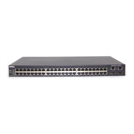
Page 22: Front Panel Indicators
Front Panel Indicators The front panel of the system contains all of the Ethernet ports and LEDs. As shown in the following figure, there is one system LED, one redundant power supply (RPS) LED, one diagnostic LED, and one LED for each port on the front panel. -
Page 23: Rps Led
RPS LED The RPS LED shows the operating status of a connected redundant power unit. Indicator states include: • Off — The redundant power supply is not connected. • Green — The redundant power supply is operating normally. • Red — The redundant power supply has failed. Console Port The console interface can be accessed from the RS-232 serial port or a Telnet connection. -
Page 24: Rear Panel Descriptions
1 0 / 1 0 0 / 1 0 0 0 P o r t s Link/Act Mode No 10/100/1000-Mbps link is established. Steady green A link is established on the port. Blinking green There is data transmission on the port. Speed Mode A 10-Mbps or 100-Mbps link is established or no link. -
Page 25: Management
Management The following sections describe methods you can use to manage the switch. Web-Based Interface After you have successfully installed the switch, you can configure the switch, monitor the LED panel, and display statistics graphically using a ® Web browser like Netscape Navigator version 4.0 and higher or Microsoft IE version 4.01 and higher. - Page 26 – CommGroup: Allows users to configure the community database – HostGroup: Allows users to configure the hosts – MiscGroup: Allows users to configure miscellaneous items – SpanGroup: Allows users to configure the Spanning Tree – ConfigGroup: Allows users to configure the system Introduction...
-
Page 27: Installation
S E C T I O N 2 I n s t a l l a t i o n Package Contents Before You Connect to the Network: Mounting-Kit Instructions Connecting the Console Port Password Protection IP Address Assignment Stacking Connecting Devices to the Switch... -
Page 28: Package Contents
Package Contents Before you begin installing the switch, confirm that your package contains the following items: • Switch • Stacking cable • AC power cord • Null modem cable • Self-adhesive rubber pads for desktop installation • Rackmount kit for rack installation Before You Connect to the Network: Mounting-Kit Instructions NOTICE: Do not connect the switch to the network until you have established... -
Page 29: Installing In A Rack
Attach rubber pads on each marked location on the bottom of the chassis. The rubber pads are optional but recommended to keep the unit from slipping. Installing in a Rack The switch can be installed in most standard 19-inch (48.3-cm) racks. To install the switch in a rack, complete the following steps: NOTE: For racks that are not prethreaded, cage... -
Page 30: Password Protection
Connect the other end of the cable to a terminal or the serial connector of a PC running terminal emulation software. Make sure the terminal emulation software is set as follows: Select the appropriate serial port (serial port 1 or serial port 2). Set the data rate to 9600 baud. -
Page 31: Ip Address Assignment
Type your password and press <Enter>. NOTE: When you login via the Web Type your password again to confirm it. Press <Enter>. interface, the username is root. Press <Ctrl><w> to save your changes. IP Address Assignment Before you can assign an IP address to the switch, you must obtain the following information from your network administrator: •... -
Page 32: Connecting Devices To The Switch
To set up a stacked configuration, it is recommended that all the Low Voltage Differential Signaling (LVDS) cables are connected before the power cables are plugged in. The root switch will begin the daisy chain with an LVDS cable routed from the “out” of the root switch to the “in” of the leaf switch. -
Page 33: Web Interface
S E C T I O N 3 We b I n t e r f a c e Web Pages Home System Manager Port Manager Address Manager Spanning Tree VLAN & CoS Port Trunking Port Mirroring SNMP Multimedia Support Statistics Save Configuration... -
Page 34: Web Pages
With web-based management, you can configure the PowerConnect 3048 NOTE: The graphics in this section may differ Fast Ethernet Managed Switch and monitor the system using a web slightly from the graphics browser. on your computer. Most web pages for the switch feature the following buttons: •... -
Page 35: Home
• System Manager • Port Manager • Address Manager • Spanning Tree • VLAN and CoS • Port Trunking • Port Mirroring • SNMP • Multimedia Support • Statistics • Save Configuration Home The Home page briefly describes the Web-based management features. Web I n t e r f a c e... -
Page 36: System Manager
System Manager The System Manager page contains all system operations and general information. It includes links to the following options: • General Info — to view general system information and perform general administration. • IP Settings — to view or edit IP parameters. •... -
Page 37: Ip Settings
IP Settings In the IP Settings page, you can manage the IP-related information about the system. The page includes the following editable fields: • IP Address • Default Gateway • Network Mask • IP Assignment Mode — Sets whether IP functionality is enabled through manual (static) configuration or set by Dynamic Host Configuration Protocol (DHCP) or Boot Protocol (BootP). -
Page 38: Security Administration
From the Save Configuration page, save your changes beyond the current session. Reboot the system from the System Manager/Reset page. Security Administration • User Authentication Mode — Selects the authentication or authentication sequence required. – Local Only — The switch authenticates the user. –... - Page 39 – Remote Only — A RADIUS server authenticates the user. • RADIUS Server IP Address — Identifies the IP address of the RADIUS server. • RADIUS Shared Secret — Specifies the text string that is shared between the switch and the RADIUS server. •...
-
Page 40: Password Administration
Password Administration Password protection is optional. You must make changes to the following fields to enable password protection. Password Protection is — Select either Enabled or Disabled. • NOTE: The default password is switch. • New Password — Type the password. •... -
Page 41: Firmware Upgrade
Firmware Upgrade From the Firmware Upgrade page, you can configure the system to download a new version of the management software. You can also set the system to use the new software without overwriting the previous version. “Software Upgrades” for more information about this process. The Firmware Upgrade page contains the following information: •... - Page 42 Supply the TPTP server IP address and configuration filename. Select Transfer Configuration File from Server. To restore the preinstalled configuration, select Restore. The Configuration page contains the following options: • TFTP Server IP Address — Inserts the TFTP Server IP Address to save or load.
-
Page 43: Reset
Reset Select Reset to reboot the switch. When prompted, confirm that you want to reset the switch. Web I n t e r f a c e... -
Page 44: Port Manager
Port Manager The Port Manager contains links to the following options: • Port Settings • GBIC Port Settings On this page, you can view and edit port parameters. For each port number listed under the Port column, you can change the following parameters listed by column name on the screen: •... -
Page 45: Gbic
• State — Describes the state of the port as determined by the Spanning Tree Protocol. • Operating Parameters — Allows automatic or manual selection of port speed and duplex mode. • Flow Control Enabled — Allows automatic or manual selection of support for flow control. -
Page 46: Address Manager
Address Manager The Address Manager allows you to manage and view dynamic and static media access control (MAC) addresses as well as set the aging time for dynamic addresses. The Address Manager page includes links to the following pages: • Static Addresses •... - Page 47 The following options are available: • MAC Address — Allows you to enter the MAC address of a system you want to set as static. • Port Selection — Allows you to select the port associated with that system. List box — Lists all static addresses. •...
-
Page 48: Dynamic Addresses
Dynamic Addresses The Dynamic Address lookup table allows you to view the MAC addresses that are currently in the address database. When addresses are in the database, the packets intended for those addresses are forwarded directly to those ports. You can filter out the table by port, virtual local area network (VLAN), and MAC address by checking those fields. -
Page 49: Address Aging
Address Aging In the Address Aging page, you can specify how long an address stays available to the switch if it is not configured as static. The following option is available: NOTE: The default value is set to 300 seconds •... -
Page 50: Static Multicast Group Settings
Static Multicast Group Settings The Static multicast settings manage multicast traffic. Each multicast address can be assigned ports that will participate in that multicast group. Ports that are added to a multicast group will forward all multicast packets from the specified multicast address to the other ports in that group. Web I n t e r f a c e... -
Page 51: Spanning Tree
Spanning Tree The Spanning Tree page contains links to the following pages that allow you to specify the parameters of the spanning tree protocol: • Bridge Settings NOTE: Spanning Tree is enabled by default. • Port Settings Bridge Settings From the Bridge Settings page, you can enable and configure the Spanning Tree. -
Page 52: Port Settings
– Forward Delay — Sets the amount of time the system spends in learning and listening states. – Bridge Priority — Sets the priority setting among other switches in the spanning tree. • Disable — Disables the spanning tree protocol on the system. To save any changes you make in this page for the current session, click Apply. -
Page 53: Vlan & Cos
• Cost — Assigned to this port for the Spanning Tree Protocol (1- 65536). A port with a lower cost is less likely to be blocked if the Spanning Tree Protocol is detecting network loops. • Fast Link — Immediately enables the port in forwarding state when a link comes up. - Page 54 • Show VLAN — Select the VLAN for which you want to edit the membership setting. • Name — Define the name of the VLAN. • VLAN ID — Enter the numeric ID of the VLAN (1 - 4094). • Remove VLAN checkbox —...
- Page 55 Click Apply. Add VLAN Membership Under the Show VLAN drop-down menu, select the VLAN you want to edit. Change the VLAN member by clicking the port icon until the desired state [T (tagged) or U (untagged)] or blank appears. Click Apply. Remove VLAN Membership Under the Show VLAN drop-down menu, select the VLAN you want to edit.
-
Page 56: Default Port Vlan
Default Port VLAN In the Default Port VLAN page, you can specify the default port VLAN ID (PVID) for each port on your switch. All untagged packets entering the switch are tagged by default with the ID specified by the port’s PVID. This page is set up in a table format. -
Page 57: Layer 3 Priority - Diffserv
Layer 3 Priority — DiffServ • DiffServ — You can change the default Type of Service (ToS) priority by selecting Normal Priority or High Priority for each class of services. This setting leverages the IETF definition of the IPv4 ToS octet in the IP packet-header by using the Differentiated Services Code. -
Page 58: Port Trunking
Port Trunking In the Port Trunking page, you can create multiple links between switches that work as one virtual, aggregate link. Trunks can be defined for similar port types only. For example, a 10/100 port cannot form a Port Trunk with a gigabit port. -
Page 59: Port Mirroring
To add a port to a trunk, click the toggle button below the port number until the correct trunk number appears. NOTICE: All ports participating in a trunk must be operating in Full Duplex mode. NOTICE: All ports participating in a trunk should have the same VLAN and CoS settings. -
Page 60: Snmp
• Source Port — Port from which all traffic will be mirrored to the monitor port. • Monitor Port — Port that receives a copy of all traffic that the source port receives. To save any changes you make in this page for the current session, click Apply. - Page 61 The following options are available: • Community Name — Allows you to type the name of the community you want to create • Get — Allows read access to the switch's SNMP information for members of the SNMP community Set — Allows write access to the switch's SNMP information for •...
-
Page 62: Host Table
Host Table From the SNMP Host Table page, you can add and remove hosts from access rights that have been granted to community groups. The permissions GET, SET, and TRAP are assigned to a community name and then these permissions are assigned to individual machines by adding those machines and their IP address to the appropriate community string. -
Page 63: Trap Settings
NOTE: The community name specified here must exist in the switch's SNMP Community Table. Trap Settings You can enable or disable authentication traps on the Trap Settings page: • Enabled — The system generates an SNMP trap upon a host authorization failure. -
Page 64: Multimedia Support
Multimedia Support In networks where multimedia applications generate multicast traffic, Internet group management protocol (IGMP) can greatly reduce unnecessary bandwidth by limiting traffic forwarding that is otherwise broadcast to the whole network. Enabling IGMP will allow individual ports to detect IGMP queries, report packets, and manage IP multicast traffic through the switch. -
Page 65: Statistics
Statistics From the Statistics page, you can chart a variety of system data. There are three types of graphs to chose from: Comparison Chart, Group Chart, and History Chart. All charts have a maximum ceiling of 2 -1. When all of the variables are set, click Draw. -
Page 66: Group Chart
Group Chart The Group Chart shows all the statistic types for one port. You must define the following variables: • Port Selection — The port for data to be monitored • Refresh Rate — The time interval between automatic refreshes •... -
Page 67: History Chart
History Chart The History Chart charts one type of statistic for any combination of ports. The chart presents data across a set time period so that you can monitor fluctuations over time. • Statistics — The type of system data to be monitored •... -
Page 68: Counter Reset
Counter Reset The Counter Reset page allows you to reset all statistics counters. Web I n t e r f a c e... -
Page 69: Utilization Summary
Utilization Summary The Utilization Summary page allows you to view (by port) the link status; percent utilization; and ratios of incoming unicast, nonunicast, and error packets. Click the Refresh button to refresh the Utilization Summary page. Web I n t e r f a c e... -
Page 70: Counter Summary
Counter Summary The Counter Summary page allows you to view all ports accumulated, unicasts and nonunicasts received and transmitted, and errors received and transmitted. Click the Refresh button to refresh the Counter Summary page. Web I n t e r f a c e... -
Page 71: Save Configuration
Save Configuration If you make any changes to the system through the Web interface, you must save the changes in the Save Configuration page. The following options are available: • Save Configuration to NVRAM — Saves changes to the system configuration. - Page 72 NOTE: Network IP settings like IP address, gateway address, and network mask are not restored by this command. Web I n t e r f a c e...
-
Page 73: Console Interface
S E C T I O N 4 C o n s o l e I n t e r f a c e User Interface Navigating in the Console Interface Password Protection Main Menu System Manager Port Manager Address Manager Spanning Tree VLAN and CoS Setup Port Trunking... -
Page 74: User Interface
You can access the console, using VT100 terminal emulation, from the NOTE: The graphics in this section may differ RS-232 serial port or a Telnet connection. The switch offers password slightly from the graphics protection for this interface. on your computer. When the Telnet session opens, under Terminal Options, select VT100 Arrows. -
Page 75: Navigating In The Console Interface
Navigating in the Console Interface Once you configure your system terminal and start the switch, you can log in to the console interface. The first time you log in, you must use the default password, which is switch The bottom of most screens includes information about navigating in and issuing commands from the console interface. - Page 76 • VLAN and CoS Setup • Port Trunking • Port Mirroring • SNMP Management • Multimedia Support • Statistics • Save Configuration To log out of the user interface, press <Ctrl><d> at any time during your Telnet session. This returns you to the login screen. Console Inter f ace...
-
Page 77: System Manager
System Manager The system manager contains all system options to configure the switch to your network as well as general information. It includes the following menus: • General Info — View general system information and perform general administration. • IP Settings — View or edit IP parameters. •... -
Page 78: Ip Settings
IP Settings This menu manages the IP-related information about the computer. The IP Settings page includes the following editable fields: • IP address • Network mask • Gateway address Press <Ctrl><w> to save any changes made. See “Installation” for more information on installation. NOTE: You must reboot the system from the System Manager/Reset... -
Page 79: Security Admin
Security Admin • User Authentication Mode — Selects the authentication or authentication sequence required. – Local Only — The switch authenticates the user. – Local then Remote — The switch attempts to authenticate the user first, and then a RADIUS server attempts to authenticate the user. - Page 80 • Allowed IP Addresses — You can enter up to 16 IP addresses in the Allowed IP Address table. • Disable Telnet/Web Access (Console Only) — Provides an option to enable or disable Telnet or Web access to the switch. NOTE: The default password is switch.
- Page 81 Console Inter f ace...
-
Page 82: Firmware Upgrade
Firmware Upgrade From the Firmware Upgrade screen, you can configure the system to download a new version of the management software. You can also set the system to use the new software without overwriting the previous version. “Software Upgrades” for more information about this process. The Firmware Upgrade screen contains the following information: •... - Page 83 – Last Saved — This option automatically shows up after the Net & save option is selected and the system is reset. • TFTP Server IP Address — Indicates the server from which the system must retrieve the new version of the software. •...
-
Page 84: Reset
Reset If you make any changes to the system through the console interface, you must save the changes in the Save Configuration screen. Once you save changes in this screen, you must go to the Reset screen and select the Reset menu option to reboot the system before the changes can take effect. -
Page 85: Port Manager
Port Manager You can arrange the port characteristics related to link operations. To change settings for any parameter on this page, select the current value and press the spacebar. This toggles between the available values for the parameter. For each port number listed under the Port column, you can change the following parameters listed by column name on the screen: •... -
Page 86: Address Manager
Address Manager The Address Manager screen includes the following options: • Static Addresses • Dynamic Addresses • Address Aging • Static Multicast Groups Administration • Static Multicast Groups Membership Static Addresses From the Static Addresses screen, you can specify the media access control (MAC) address for specific ports that will not be purged from the bridge table by the aging function. - Page 87 If all the information is correct, the new entry appears in the screen in order by port ID. Console Inter f ace...
-
Page 88: Dynamic Addresses
Dynamic Addresses The Dynamic Addresses lookup table allows you to view the MAC addresses that are currently in the address database. When addresses are in the database, the packets intended for those addresses are forwarded directly to those ports. You can filter out the table by port, VLAN, and MAC address by checking those fields. -
Page 89: Address Aging
Address Aging In the Address Aging screen, you can specify how long an address stays available in the bridge tables. The timer can be set to the minimum and maximum values range indicated within parentheses. Console Inter f ace... -
Page 90: Static Multicast Groups Administration
Static Multicast Groups Administration Static multicast is a way to manage multicast traffic. Each multicast address can be assigned ports that will participate in that multicast group. Ports that are added to a multicast group will forward all multicast packets from the specified multicast address to the other ports in that group. -
Page 91: Static Multicast Groups Membership
Static Multicast Groups Membership Static multicast is a way to manage multicast traffic. Each multicast address can be assigned ports that will participate in that multicast group. Ports that are added to a multicast group will forward all multicast packets from the specified multicast address to the other ports in that group. -
Page 92: Spanning Tree
Spanning Tree The Spanning Tree screen includes the following options: • Bridge Settings • Port Settings Console Inter f ace... -
Page 93: Bridge Settings
Bridge Settings From the Bridge Settings screen, you can enable and configure the spanning tree. The following options are available: • Enable — Turns the spanning tree on. If you enable the spanning tree, you must complete the following fields: Hello Time —... -
Page 94: Port Settings
Port Settings In the Port Settings screen, you can specify spanning-tree parameters for each port. This screen is in a table format. For each port number listed under the Port column, the following fields are available: • Priority — Priority assigned to this port for the Spanning Tree Protocol (0 - 255). -
Page 95: Vlan And Cos Setup
VLAN and CoS Setup From the VLAN Management menu, you can configure up to 64 802.1Q VLANs. VLANs allow PCs, workstations, and other resources, including printers and file servers, to be organized into logical, broadcast domains so that only devices within the same domain can communicate with each other. The VLAN Management screen shows the information regarding all configured VLANs. -
Page 96: Vlan Administration
VLAN Administration You can add up to 64 VLANs with unique ID numbers and names. VLAN ID numbers must be in the range of 1 to 4094. Add a VLAN • Type a unique numeric VLAN ID and press <Enter>. •... -
Page 97: Vlan Membership
VLAN Membership This matrix allows for real-time management of up to 64 VLANs. To add a port to a VLAN, position the cursor in the desired matrix location and toggle the options with the spacebar. • <U>: Port is a member of the VLAN. All packets transmitted by the port will be untagged, that is, not carry a tag and therefore not carry VLAN or CoS information. -
Page 98: Pvid Settings
PVID Settings In the PVID Settings screen, you can specify the Port VLAN ID (PVID) for each port on your switch. All untagged packets entering the switch are tagged by default with the ID specified by the port’s PVID. Console Inter f ace... -
Page 99: Cos Settings
CoS Settings Port Priority allows the user to specify which ports have greater precedence in situations where traffic may be buffered in the switch due to congestion. The ports with a setting of “high” will transmit their packets before those with a “normal”... - Page 100 Console Inter f ace...
-
Page 101: Port Trunking
Port Trunking In the Port Trunking page, you can create multiple links between switches that work as one virtual, aggregate link. You can create four trunks at a time, with each trunk containing up to eight ports. Only ports of the same speed can belong to a single trunk: 10/100 Fast Ethernet ports and Gigabit Ethernet ports cannot be in the same trunk. -
Page 102: Port Mirroring
Port Mirroring From the Port Mirroring menu, you can monitor traffic on a specific port. The switch can monitor only single-direction traffic, either transmission or reception. When port mirroring is enabled, all the transmission or receiving traffic of the mirrored port is forwarded to the mirroring port. The following options are available: •... -
Page 103: Snmp Management
SNMP Management The SNMP menu includes the following options: • Community Table • Host Table • Trap Settings Community Table In the Community Table page, you can create different communities and customize access. The public string has Get privileges by default. The following options are available: •... -
Page 104: Host Table
Host Table From the Host Table page, you can add and remove hosts from access rights that have been granted to community groups. The permissions GET, SET, and TRAP are assigned to a community name and then these permissions are assigned to individual machines by adding those machines and their IP addresses to the appropriate community string. - Page 105 Add host Enter the host name, IP address, and the community string. Press <Enter> after each entry to move to the next field. In the Status field, press the spacebar until the desired status is displayed. Press <Ctrl><w> to save all changes. Console Inter f ace...
-
Page 106: Trap Settings
Trap Settings The Trap Settings page allows you to set up authentication traps. The following options are available: • Authentication Trap Enabled — The system generates an SNMP trap upon a host – authorization failure. – Disabled — The system does not generate authentication traps. All hosts in community strings with trap privileges are notified when a trap condition occurs. -
Page 107: Multimedia Support
Multimedia Support From the multimedia support page, IGMP and High Priority Optimization can be enabled or disabled. IGMP With Internet Group Management Protocol (IGMP) Snooping, you can configure the switch to forward multicast traffic intelligently. Based on the IGMP query and report messages, the switch forwards traffic only to the ports that request multicast traffic. -
Page 108: High-Priority Optimization
High-Priority Optimization NOTICE: Enabling high-priority optimization can effectively disable flow- control for normal-priority packets. The High-Priority Optimization setting implements a priority-based head- NOTE: Enabling high- priority optimization can of-line blocking prevention algorithm in the system. This algorithm ensures improve overall system that in the case of traffic congestion, normal priority packets do not hold up performance for networks high-priority packets. -
Page 109: Save Configuration
Save Configuration If you make any changes to the system through the console interface, you must save the changes in the Save Configuration screen. Save Configuration to NVRAM — Save all changes made in your • session to NVRAM. • Restore Factory Defaults —... - Page 110 Console Inter f ace...
-
Page 111: Software Upgrades
S E C T I O N 5 S o f t w a r e U p g r a d e s Upgrade Procedure... -
Page 112: Upgrade Procedure
Upgrade Procedure The application software is field upgradable. The new software must reside NOTE: Perform the upgrade procedure from on a TFTP server that can be accessed by the switch. the console interface via an RS-232 serial port. To upgrade the software, you must go to the Firmware Upgrade screen. When using a Telnet Complete the following steps: session or Web interface... -
Page 113: Appendix
S E C T I O N 6 A p p e n d i x VLAN Description VLAN Examples Troubleshooting Technical Specifications Technical Assistance Regulatory Notices... -
Page 114: Vlan Description
VLAN Description Packets received by the switch are treated in the following ways: • When an untagged packet enters a port, the system automatically tags it with the port’s default VLAN ID tag number. Each port has a default VLAN ID setting that is user configurable. The default setting is 1. Change the default VLAN ID setting for each port from the port’s respective Port Configuration page. - Page 115 In the VLAN Membership page, use the spacebar to toggle the matrix until the desired ports are all members of the selected VLAN. Appendix...
- Page 116 To allow untagged packets to participate in the new VLAN, change the Port VLAN IDs for the relevant ports. Appendix...
-
Page 117: Example 2
Example 2 Example 2 steps through a more elaborate setup illustrating all possible scenarios for a comprehensive understanding of tagged VLANs. Set up VLANs as shown in the following illustration: Configure VLAN membership: This example includes two VLANs, using stack 1 only. Appendix... - Page 118 Appendix...
- Page 119 Appendix...
- Page 120 Set up the Port VLAN IDs as shown in the following illustration: The specific ports shown in the previous illustration have the following port VLAN ID settings. The port VLAN ID settings for each port are configured in the PVID Settings page: Port 01: 2 Port 05: 5 Port 09: 10...
-
Page 121: Troubleshooting
• If an untagged packet enters Port 1, the switch tags it with a VLAN tag value of 2. It is then dropped since Port 1 has no membership with VLAN ID 2. • If a tagged packet with a VLAN tag value 10 enters Port 9, it has access to Ports 1, 10, 11, and 12. -
Page 122: Ports
Ports The following section discusses troubleshooting associated with ports: • Port does not work. Check the following: – The cable connections are secure and the cables are connected to the correct ports at both ends of the link. – The port status is configured at “Enable” and the autonegotiation feature is enabled at the switch. -
Page 123: Technical Specifications
Technical Specifications Standards Ethernet types supported IEEE 802.3 Type 10Base-T, IEEE 802.3u Type 100 Base-TX, IEEE 802.3z, IEEE 802.3ab Other standards supported IEEE 802.3x, IEEE 802.1D, IEEE 802.1Q, IEEE 802.1p, IEEE 802.3ad Interfaces 10/100BASE-T ports 10/100/1000BASE-T ports SFP GBIC slots Gigabit stacking ports RS-232 connector Indicators... - Page 124 Environmental Temperature: 0º to 40ºC Operating Storage –20º to 70ºC Relative humidity: Operating 10% to 90% Storage 5% to 90% Appendix...
-
Page 125: Technical Assistance
Technical Assistance If you need help with a technical problem, Dell is ready to assist you. CAUTION: If you need to remove the computer covers, first disconnect the computer power and modem cables from all electrical outlets. Make a copy of the Diagnostics Checklist and fill it out. -
Page 126: Autotech Service
AutoTech Service Dell's automated technical support service—AutoTech—provides recorded answers to the questions most frequently asked by Dell customers about their portable and desktop computers. When you call AutoTech, use your touch-tone telephone to select the subjects that correspond to your questions. -
Page 127: Automated Order-Status Service
Automated Order-Status Service To check on the status of any Dell products that you have ordered, you can go to support.dell.com, or you can call the automated order-status service. A recording prompts you for the information needed to locate and report on your order. -
Page 128: Before You Call
Dell’s receiving dock and returned to you. Before You Call NOTE: Have your Express Service Code ready when you call. The code helps Dell’s automated-support telephone system direct your call more efficiently. Remember to fill out the Diagnostics Checklist. If possible, turn on your computer before you call Dell for technical assistance and call from a telephone at or near the computer. -
Page 129: Contacting Dell
Phone number: Service tag (bar code on the back of the computer): Express Service Code: Return Material Authorization Number (if provided by Dell support technician): Switch Name and Firmware Version: Error message, beep code, or diagnostic code: Description of problem and troubleshooting procedures you performed:... - Page 130 NOTE: Toll-free numbers are for use within the country for which they are listed. When you need to contact Dell, use the electronic addresses, telephone numbers, and codes provided in the following table. If you need assistance in determining which codes to use, contact a local or an international operator.
- Page 131 International Access Code Website and E-Mail Address Local Numbers, and Country Code Toll-Free Numbers City Code Austria (Vienna) Website: support.euro.dell.com International Access Code: 900 E-mail: tech_support_central_europe@dell.com Country Code: 43 Home/Small Business Sales 01 795 67602 City Code: 1 Home/Small Business Fax...
- Page 132 Country (City) Department Name or Service Area, Area Codes, International Access Code Website and E-Mail Address Local Numbers, and Country Code Toll-Free Numbers City Code Brunei Customer Technical Support (Penang, Malaysia) 604 633 4966 Country Code: 673 Customer Service (Penang, Malaysia) 604 633 4949 Transaction Sales (Penang, Malaysia) 604 633 4955...
- Page 133 Website and E-Mail Address Local Numbers, and Country Code Toll-Free Numbers City Code China (Xiamen) Tech Support website: support.ap.dell.com/china Country Code: 86 Tech Support E-mail: cn_support@dell.com City Code: 592 Tech Support Fax 818 1350 Home and Small Business Technical Support...
- Page 134 International Access Code Website and E-Mail Address Local Numbers, and Country Code Toll-Free Numbers City Code Denmark (Copenhagen) Website: support.euro.dell.com International Access Code: 00 E-mail Support (portable computers): den_nbk_support@dell.com Country Code: 45 E-mail Support (desktop computers): den_support@dell.com E-mail Support (servers): Nordic_server_support@dell.com...
- Page 135 International Access Code Website and E-Mail Address Local Numbers, and Country Code Toll-Free Numbers City Code France (Paris) (Montpellier) Website: support.euro.dell.com International Access Code: 00 E-mail: support.euro.dell.com/fr/fr/emaildell/ Country Code: 33 Home and Small Business City Codes: (1) (4) Technical Support...
- Page 136 Hong Kong Technical Support (Dimension™ and Inspiron™) 296 93188 International Access Code: 001 Technical Support (OptiPlex™, Latitude™, and 296 93191 Dell Precision™) Country Code: 852 Customer Service (non-technical, post-sales issues) 800 93 8291 Transaction Sales toll-free: 800 96 4109 Large Corporate Accounts HK...
- Page 137 International Access Code Website and E-Mail Address Local Numbers, and Country Code Toll-Free Numbers City Code Italy (Milan) Website: support.euro.dell.com International Access Code: 00 E-mail: support.euro.dell.com/it/it/emaildell/ Country Code: 39 Home and Small Business City Code: 02 Technical Support 02 577 826 90...
- Page 138 0120-198-226 Technical Support outside of Japan (Dimension and 81-44-520-1435 Inspiron) Technical Support (Dell Precision™, OptiPlex™, toll-free:0120-198-433 and Latitude™) Technical Support outside of Japan (Dell Precision, 81-44-556-3894 OptiPlex, and Latitude) 24-Hour Automated Order Service 044-556-3801 Customer Care 044-556-4240 Business Sales Division (up to 400 employees)
- Page 139 Sales (Austin, Texas, U.S.A.) 512 728-4397 SalesFax (Austin, Texas, U.S.A.) 512 728-4600 or 512 728-3772 Luxembourg Website: support.euro.dell.com International Access Code: 00 E-mail: tech_be@dell.com Country Code: 352 Technical Support (Brussels, Belgium) 02 481 92 88 Home/Small Business Sales (Brussels, Belgium)
- Page 140 Country Code: 31 (Enterprise): nl_server_support@dell.com City Code: 20 (Latitude): nl_latitude_support@dell.com (Inspiron): nl_inspiron_support@dell.com (Dimension): nl_dimension_support@dell.com (OptiPlex): nl_optiplex_support@dell.com (Dell Precision): nl_workstation_support@dell.com Technical Support 020 674 45 00 Technical Support Fax 020 674 47 66 Home/Small Business Customer Care 020 674 42 00...
- Page 141 International Access Code Website and E-Mail Address Local Numbers, and Country Code Toll-Free Numbers City Code New Zealand E-mail (New Zealand): nz_tech_support@dell.com International Access Code: 00 E-mail (Australia): au_tech_support@dell.com Country Code: 64 Home and Small Business 0800 446 255 Government and Business...
- Page 142 International Access Code Website and E-Mail Address Local Numbers, and Country Code Toll-Free Numbers City Code Portugal E-mail: support.euro.dell.com/es/es/emaildell/ International Access Code: 00 Technical Support 800 834 077 Country Code: 35 Customer Care 800 300 415 or 800 834 075...
- Page 143 International Access Code: 00 E-mail: swe_support@dell.com Country Code: 46 E-mail Support for Latitude and Inspiron: Swe-nbk_kats@dell.com City Code: 8 E-mail Support for OptiPlex: Swe_kats@dell.com E-mail Support for Servers: Nordic_server_support@dell.com Technical Support 08 590 05 199 Relational Customer Care 08 590 05 642...
- Page 144 International Access Code Website and E-Mail Address Local Numbers, and Country Code Toll-Free Numbers City Code Switzerland (Geneva) Website: support.euro.dell.com International Access Code: 00 E-mail: swisstech@dell.com Country Code: 41 E-mail for French-speaking HSB and Corporate Customers: support.euro.dell.com/ch/fr/emaildell/ City Code: 22...
- Page 145 Area Codes, International Access Code Website and E-Mail Address Local Numbers, and Country Code Toll-Free Numbers City Code U.K. (Bracknell) Website: support.euro.dell.com International Access Code: 00 Customer Care website: dell.co.uk/lca/customerservices Country Code: 44 E-mail: dell_direct_support@dell.com City Code: 1344 Technical Support (Corporate/Preferred...
- Page 146 1-888-798-7561 Software and Peripherals Sales toll-free: 1-800-671-3355 Spare Parts Sales toll-free: 1-800-357-3355 Extended Service and Warranty Sales toll-free: 1-800-247-4618 toll-free: 1-800-727-8320 Dell Services for the Deaf, Hard-of-Hearing, or toll-free: 1-877-DELLTTY Speech-Impaired (1-877-335-5889) U.S. Virgin Islands General Support 1-877-673-3355 Venezuela...
-
Page 147: Regulatory Notices
Plug the computer into a different outlet so that the computer and the receiver are on different branch circuits. If necessary, consult a Dell Technical Support representative or an experienced radio/television technician for additional suggestions. Dell™ computer systems are designed, tested, and classified for their intended electromagnetic environment. -
Page 148: Fcc Notices (U.s. Only)
EMC classification for the intended environment. For parallel printers, a cable is available from Dell. If you prefer, you can order a cable from Dell on the World Wide Web at accessories.us.dell.com/sna/category.asp?category_id=4117. Most Dell computer systems are classified for Class B environments. -
Page 149: This Device Must Accept Any Interference Received, Including
• This device must accept any interference received, including interference that may cause undesired operation. Class A This equipment has been tested and found to comply with the limits for a Class A digital device pursuant to Part 15 of the FCC Rules. These limits are designed to provide reasonable protection against harmful interference when the equipment is operated in a commercial environment. -
Page 150: Only)
Industry Canada (IC) Interference-Causing Equipment Standard #3 (ICES-003) as Class B digital devices. To determine which classification (Class A or B) applies to your computer system (or other Dell digital apparatus), examine all registration labels located on the bottom, side, or the back panel of your computer (or other digital apparatus). - Page 151 (RF) interference, in which case the user may be required to take adequate measures. This Dell device is classified for use in a typical Class B domestic environment. A "Declaration of Conformity" in accordance with the preceding directives and standards has been made and is on file at Dell Computer Corporation Products Europe BV, Limerick, Ireland.
- Page 152 ® ENERGY STAR Emblem ® The EPA's ENERGY STAR Computers program is a joint effort between the EPA and computer manufacturers to reduce air pollution by promoting energy-efficient computer products. The EPA estimates that use of ® ENERGY STAR computer products can save computer users up to two billion dollars annually in electricity costs.
-
Page 153: Vcci Notice (Japan Only)
VCCI Notice (Japan Only) Most Dell computer systems are classified by the Voluntary Control Council for Interference (VCCI) as Class B information technology equipment (ITE). However, the inclusion of certain options can change the rating of some configurations to Class A. - Page 154 Class A ITE This is a Class A product based on the standard of the Voluntary Control Council for Interference (VCCI) for information technology equipment. If this equipment is used in a domestic environment, radio disturbance may arise. When such trouble occurs, the user may be required to take corrective actions.
- Page 155 (or other Dell digital device), examine the Republic of Korean Ministry of Information and Communications (MIC) registration labels located on your computer (or other Dell digital device). The MIC label may be located separately from the other regulatory marking applied to your product. Line two of the label identifies the emissions class for the product—"(A)"...
- Page 156 MIC Class A Regulatory Label If the regulatory label includes the following marking, your computer is a Class A product: Class B Device Please note that this device has been approved for nonbusiness purposes and may be used in any environment, including residential areas. MIC Class B Regulatory Label If the regulatory label includes the following marking, your computer is a Class B product.
- Page 157 Polish Center for Testing and Certification Notice The equipment should draw power from a socket with an attached protection circuit (a 3-prong socket). All equipment that works together (computer, monitor, printer, and so on) should have the same power supply source.
- Page 158 BSMI Notice (Taiwan Only) If you find a mark on the regulatory label on the bottom, side, or back panel of your computer, the following section is applicable: Appendix...
- Page 159 Appendix...
-
Page 160: Nom Information (Mexico Only)
(NOM): Exporter: Dell Computer Corporation One Dell Way Round Rock, TX 78682 Importer: Dell Computer de México, S.A. de C.V. Paseo de la Reforma 2620 - 11° Piso Col. Lomas Altas 11950 México, D.F. Ship to: Dell Computer de México, S.A. - Page 161 Input current rating: 1.5 A Appendix...
- Page 162 Appendix...