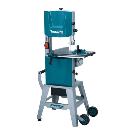
Makita LB1200F Instruction Manual
Band saw
Hide thumbs
Also See for LB1200F:
- Instruction manual (73 pages) ,
- Instruction manual (16 pages) ,
- Instruction manual (36 pages)
Advertisement
Table of Contents
- 1 Specifications
- 2 Safety Instructions
- 3 Additional Safety Rules for Tool
- 4 Functional Description
- 5 Push Stick
- 6 Miter Gauge
- 7 Installing the Rip Fence
- 8 Changing the Band Saw Blade
- 9 Cutting Speed Adjustment
- 10 Tensioning the Band Saw Blade
- 11 Aligning the Band Saw Blade
- 12 Quick Release Lever
- 13 Upper Blade Guide Adjustment
- 14 Operation
- 15 How to Move Machine
- 16 Maintenance
- Download this manual
See also:
Instruction Manual
Advertisement
Table of Contents

Related Manuals for Makita LB1200F


Summary of Contents for Makita LB1200F
- Page 1 Band Saw LB1200F INSTRUCTION MANUAL IMPORTANT: Read Before Using.
-
Page 2: Specifications
SPECIFICATIONS Model LB1200F Wheel size 305 mm Max. cutting capacity 165 mm High 840 min (50 Hz)/1,040 min (60 Hz) No load speed 420 min (50 Hz)/520 min (60 Hz) 13.3 m/s (800 m/min) (50 Hz)/ High 16.7 m/s (1,000 m/min) (60 Hz) Cutting speed 6.7 m/s (400 m/min) (50 Hz)/... -
Page 3: Additional Safety Rules For Tool
15. Disconnect tools. 12. NEVER wear gloves during operation. When not in use, before servicing and when changing 13. Keep hands out of the line of the saw blade. accessories such as blades, bits and cutters. 14. NEVER stand or permit anyone else to stand in line with 16. - Page 4 Wheel Knob (For tensioning blade) Upper cover Knob (For securing upper housing door) Knob (For adjusting blade guide) Knob (For securing blade guide) Upper blade guide Blade Light switch Switch Rip fence Knob (For securing lower housing door) Knob (For tensioning V-belt) Lower cover Driving belt Carry Handle...
- Page 5 INSTALATION Securing the band saw stand If during operation there is any tendency for the band saw to tip over, slide or move, the band saw stand be secured to the floor. Frame • After attaching the stand, attach the handle and tires. Handle Washer Hex socket...
- Page 6 How to load dust box The dust box is loaded from the underside of the table saw. When loading, insert Securing plate spring (for securing) at inside edge of the machine’s positioning hole, slot both Position hole shoulders of dust box onto rails, and then slide toward the outside. hole Once the leading edge of the securing plate spring fits into the machine’s securing Rail...
- Page 7 Secure table to trunnion using four hex bolts. Trunnion Table Hex bolts Hex bolts Pin is inserted at time of shipping, so please pull it out. Table Installing the guide rail • Fasten the guide rail with four each thumb screws and washers to the table. Washer Thumb screw Guide rail...
-
Page 8: Functional Description
FUNCTIONAL DESCRIPTION Switch action Switch cover CAUTION: Light switch OFF switch • Before operation, make sure that the tool is turned on and off. The switch cover can be opened easily by sliding it upwards. To start the tool, press the ON (I) button. To stop it, press the OFF (O) button or the switch cover. -
Page 9: Installing The Rip Fence
Installing the Rip Fence The rip fence can be used on both sides of the blade. When the rip fence is moved from one side of the saw blade to the other the fence needs to reversed. Rip fence Reversing the fence Knob (A) 1. -
Page 10: Changing The Band Saw Blade
ASSEMBLY Guide rail Changing the band saw blade CAUTION: • Contacting the band saw blade even with the band saw blade at standstill may cause a personal injury. • Saw blade is dangerous. Be sure to wear gloves when handling saw blade in situations such as removing from packaging, mounting or replacing blade. - Page 11 4. Open the lower blade guard. Saw blade 5. Set the upper blade guide to its lowest position. Saw housing Upper blade guide 6. Loosen quick release lever until the band saw blade has slackened. Lower blade guard 7. To remove the band saw blade, guide it through. - the slot in the saw blade.
-
Page 12: Cutting Speed Adjustment
Cutting speed adjustment 1. Open the lower cover. Lower band saw wheel 2. Slacken driving belt by turning the knob clockwise. 3. Put driving belt on the required pulley of the driving wheel (lower band saw wheel) and the corresponding motor pulley-note label inside the lower cover. CAUTION: The driving belt must run either on both front or both rear pulleys. -
Page 13: Tensioning The Band Saw Blade
FUNCTIONAL DESCRIPTION Tensioning the Band saw Blade Knob CAUTION: Too much tension can cause the band saw blade to break. Too little tension can cause the driven band saw wheel to slip and the band saw blade to stop. 1. Raise upper blade guide fully. Using the scale as guide, and taking the blade width into consideration, turn the knob to adjust tension. -
Page 14: Quick Release Lever
Quick release lever Quick release lever With the quick release lever the saw blade tension is released. Clockwise: Reduce tension Counterclockwise: Increase tension Upper blade guide adjustment Adjusting knob The height of the upper blade guide needs to be adjusted: prior to every cutting/operation, to accommodate the height of the work piece (the upper blade guide should be set approx. - Page 15 1. Loosen bolt C, and adjust bearing holder, so that guide bearing is positioned 1 or 2 mm from bottom of blade. Guide bearing 2. Loosen bolt A, and adjust thrust bearing to a position of 0.5 mm from rear of blade.
- Page 16 Align the lower blade guide The lower blade guide consists of: - a thrust bearing (supporting the band saw blade from the rear). - two guide bearings (providing lateral support). These parts need to be readjusted after every band saw blade change or tracking adjustment: Note: Bolt A...
-
Page 17: Operation
Lock lever Operation Danger: To reduce the risk of personal injury as much as possible, the following safety recommendations should be observed when operating the saw. CAUTION: • Do not touch the saw blade when cutting. • During saw operation, wear safety glasses, but do not wear gloves. •... - Page 18 Lock lever Handle Connecting to vacuum cleaner Cleaner operations can be performed by connecting the tool to Makita vacuum cleaner or dust collector. If a dust extractor is fitted to the large opening collector, rearrange dust collector to ensure it has a large opening.
-
Page 19: How To Move Machine
ACCESSORIES CAUTION: • These accessories or attachments are recommended for use with your Makita tool specified in this manual. The use of any other accessories or attachments might present a risk of injury to persons. Only use accessory or attachment for its stated purpose. - Page 20 Makita Corporation www.makita.com JM21080008...