Bosch AMAX 2100 Installation Manual
Hide thumbs
Also See for AMAX 2100:
- Installation manual (164 pages) ,
- Operation manual (52 pages) ,
- Quick start manual (38 pages)
Table of Contents
Advertisement
Advertisement
Table of Contents

Related Manuals for Bosch AMAX 2100


Summary of Contents for Bosch AMAX 2100
- Page 1 AMAX 2100 / 3000 / 4000 Installation Guide...
-
Page 3: Table Of Contents
AMAX 2100 / 3000 / 4000 Table of Contents | en Table of contents Graphics Safety Short Information Keypad Indicators System overview Optional Modules and Peripheral Devices Bosch Option Bus Keypad 5.2.1 General 5.2.2 Address Setting 5.2.3 Wiring 5.2.4 Status Indicator DX2010 5.3.1... - Page 4 | Table of Contents AMAX 2100 / 3000 / 4000 Certification 6.5.1 EN 50131-3 Grade 2, Environmental Class 2 - AMAX 2100 / 3000 / 4000 6.5.2 NFA2P AFNOR / CNPP - AMAX 2100 / 3000 / 4000 6.5.3 INCERT - AMAX 4000 6.5.4...
-
Page 5: Amax 2100 / 3000 / 4000 Table Of Contents | En
AMAX 2100 / 3000 / 4000 Table of Contents | en PC Programming 8.2.1 Direct Connection 8.2.2 Modem Connection 8.2.3 IP Connection Address Programming Communication and Report Programming 9.1.1 Receiver Programming 9.1.2 Reports Programming 9.1.3 Communication Operations Programming User and Code Programming 9.2.1... -
Page 6: Graphics
| Graphics AMAX 2100 / 3000 / 4000 Graphics Figure 1.1: Wiring diagram for AMAX panel 2100 / 3000 2014.11 | 02 | F.01U.267.112 Installation Guide Bosch Sicherheitsysteme GmbH... - Page 7 AMAX 2100 / 3000 / 4000 Graphics | en AUX 1: < 900mA AUX 2: < 900mA AUX1 AUX2 AUX2 AUX1 RING +12V +12V 18VAC@50VA Keypads: IUI-AMAX4-TEXT Battery IUI-SOL-TEXT 230V ~50Hz 12V 7Ah IUI-AMAX3-LED16 230mA 12V < 18Ah IUI-AMAX3-LED8 Fuse 1 A 5-16 Inst.
-
Page 8: Safety
| Safety AMAX 2100 / 3000 / 4000 Safety Danger! Electricity Injuries due to electricity are possible if the system is not operated correctly or if the system is opened or modified not accordingly to this manual. – Disconnect all Telecommunication Network Connectors before switching off the power. - Page 9 AMAX 2100 / 3000 / 4000 Safety | en – Under normal conditions of use, replace the battery every 3-5 years. – Recycle the battery after replacement according to local regulations. Caution! Installation Damage or malfunction of the system is possible if the system is not mounted and installed correctly.
-
Page 10: Short Information
| Short Information AMAX 2100 / 3000 / 4000 Short Information Congratulations on selecting the AMAX panel for your installation. Spend some time reading through this guide and familiarize yourself with the outstanding installation and operation features of this system so that you can get the most from your unit. In all aspects of planning, engineering, styling, operation, convenience, and adaptability, we try to anticipate your every possible requirement. - Page 11 AMAX 2100 / 3000 / 4000 Short Information | en Fast flash (0.25 seconds lights on/ Programming mode or code 0.25 seconds lights off) function mode. AWAY indicator flashes simultaneously. When bypass function is performed, only the STAY indicator flashes.
-
Page 12: System Overview
| System overview AMAX 2100 / 3000 / 4000 System overview Radion LCD / LED Keypad Text Keypad DX2010 AMAX 3000 AMAX 3000 Option Bus B426 DX4020G DX3010 PSTN GSM/ GPRS Video A Link Plus AMAX 3000 AMAX 2100 / 3000 Figure 4.1: AMAX 2100/3000 Overview... -
Page 13: Optional Modules And Peripheral Devices
Optional Modules and Peripheral Devices Bosch Option Bus The AMAX panel provides BOSCH option bus 1 and option bus 2 (only for AMAX 4000) to connect modules and devices. Each module can be connected to each bus. A maximum of 14 modules (8 keypads) can be connected to each bus. -
Page 14: Keypad
| Optional Modules and Peripheral Devices AMAX 2100 / 3000 / 4000 Keypad 5.2.1 General AMAX panel supports five types of keypad as follows: – IUI-AMAX4-TEXT (LCD Text Keypad) – IUI-SOL-TEXT (LCD Text Keypad) – IUI-AMAX3-LED16 (16 Zone LED Keypad) –... -
Page 15: Wiring
AMAX 2100 / 3000 / 4000 Optional Modules and Peripheral Devices | en Figure 5.1: 6-Position DIP Switch DIP switches 5 and 6 are not used. Address setting for IUI-AMAX-LED8 and IUI-AMAX-LCD8 Keypads IUI-AMAX-LED8 and IUI-AMAX-LCD8 keypads can be set only to address 1 or address 2 through the address jumper. -
Page 16: Dx2010
| Optional Modules and Peripheral Devices AMAX 2100 / 3000 / 4000 DX2010 5.3.1 General The AMAX panel supports DX2010 input expansion modules. Each expansion module supports up to 8 zone inputs. For information on the installation, refer to Module Installation, page 25. -
Page 17: Wiring
AMAX 2100 / 3000 / 4000 Optional Modules and Peripheral Devices | en Example : Data Bus Location 103 - DIP Settings Figure 5.3: DX2010 DIP Switch Settings Notice! When the data bus address is changed, the module and the panel need to be re-powered to enable the new address 5.3.3... -
Page 18: Status Indicator
| Optional Modules and Peripheral Devices AMAX 2100 / 3000 / 4000 5.3.4 Status Indicator LED Condition Denotation Trouble Condition: – Grounding Conductor is not connected or there is a communication failure between the module and the AMAX panel –... -
Page 19: Wiring
AMAX 2100 / 3000 / 4000 Optional Modules and Peripheral Devices | en 5.4.3 Wiring The following table and graphic show how to wire DX3010 to the option bus of the AMAX panel. Power Supply Wire diameter of 0.8mm Wire diameter of 1.2mm AMAX panel 12.2m... -
Page 20: Wiring
| Optional Modules and Peripheral Devices AMAX 2100 / 3000 / 4000 5.5.3 Wiring The following graphic shows how to wire B426 to the option bus 1 or 2 of the AMAX panel. Make sure, that the cable doesn’t exceed 150 meters. -
Page 21: B450 With B442
AMAX 2100 / 3000 / 4000 Optional Modules and Peripheral Devices | en B450 with B442 5.6.1 General Use B450 in combination with a plug-in communicator for primary or backup alarm communication, remote panel programming and other remote applications. The B450 supports Conettix IP protocol with full authentication, 256 bit AES encryption and resistance to Denial of Service attacks. -
Page 22: Dx4020-G
| Optional Modules and Peripheral Devices AMAX 2100 / 3000 / 4000 LED Condition Denotation Heartbeat LED of B450 Trouble Condition Stable flash Normal Operation 3 quick flashes Communication error Power failure or other failure conditions Status LED of B442... -
Page 23: Status Indicator
AMAX 2100 / 3000 / 4000 Optional Modules and Peripheral Devices | en AMAX 2100 / 3000 DX4020G AMAX 4000 Figure 5.9: GPRS mode in support of IP 1RING 1RING DX4020G RING Figure 5.10: GSM mode in support of PSTN (Contact ID) 5.7.4... -
Page 24: Rf Radion Receiver
| Optional Modules and Peripheral Devices AMAX 2100 / 3000 / 4000 RF Radion Receiver 5.8.1 General The RADION receiver OP is a wireless receiver that connects the RADION wireless system components to the AMAX panel 3000/4000. Features include the following: –... -
Page 25: Installation
AMAX 2100 / 3000 / 4000 Installation | en Installation This chapter describes the installation and the system power up of the AMAX panel. Danger! Electricity Injuries due to electricity are possible if the system is not operated correctly or if the system is opened or modified not accordingly to this manual. -
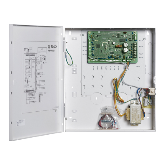
Page 26: Battery Installation
| Installation AMAX 2100 / 3000 / 4000 E N √ E N √ Enclosure - Standard Enclosure with mounting plate Figure 6.1: Enclosure Standard / Enclosure with mounting plate E N √ Figure 6.2: Enclosure Standard / Enclosure with mounting plate Battery Installation The AMAX Panel supports one sealed lead-acid rechargeable battery. -
Page 27: System Power Up
AMAX 2100 / 3000 / 4000 Installation | en – Make sure that the grounding terminal is always connected and that N, L1 or xx are connected correctly. – Make sure to first disconnect the positive wire of the battery when removing it from the system. -
Page 28: System Status Indicator
| Installation AMAX 2100 / 3000 / 4000 To reduce false alarms caused by system power up (or by power supply restoration after both mains supply and AUX power supply fail), the AMAX panel is does not perform zone tests within one minute after the system power up. -
Page 29: En 50131-3 Grade 2, Environmental Class 2 - Amax 2100 / 3000 / 4000
AMAX 2100 / 3000 / 4000 Installation | en 6.5.1 EN 50131-3 Grade 2, Environmental Class 2 - AMAX 2100 / 3000 / 4000 Certification Body: VDS Schadenverhütung Amsterdamer Str. 172 50735 Köln Website: www.vds.de The panel complies with the following standards:... -
Page 30: Incert - Amax 4000
Prerequisites for an NFa2p conform installation: When an NFa2p conform installation is made, the environmental class of the panel is “1” 6.5.3 INCERT - AMAX 4000 6.5.4 SFF – AMAX 2100 / 3000 / 4000 Certification Body: VDS Schadenverhütung Amsterdamer Str. 172 50735 Köln Website: www.vds.de... - Page 31 AMAX 2100 / 3000 / 4000 Installation | en The panel complies with the following standards: SSF 1014 Edition 4 Alarm class 1 Bosch Sicherheitsysteme GmbH Installation Guide 2014.11 | 02 | F.01U.267.112...
-
Page 32: Settings
Example You can set up dialer 1 to report to receiver 1 in Bosch Network (Conettix) format and set up dialer 2, dialer 3, and dialer 4 to report to a receiver of a central monitoring station in Contact ID format only, if dialer 1 is unsuccessful. - Page 33 AMAX 2100 / 3000 / 4000 Settings | en Digit Required Number to Program Digit Required Number to Program 4 sec pause Terminal Table 7.1: Dialing Digits How to program an IP address and port: Use no punctuation in the IP address.
- Page 34 SIA allows transmitting system ID, event code, zone ID, area ID, event time, and also event text. Conettix IP Format The AMAX panel supports Conettix IP format. An AMAX panel with DX4020G and B426 is able to connect to Bosch Receivers 6600/6100 using the Conettix IP format. Event Description Dialer Event...
- Page 35 AMAX 2100 / 3000 / 4000 Settings | en Event Description Dialer Event Recall Event Event BURG 24-HOUR RESTORE 3133 √ SENSOR FAULT 1380 √ SENSOR FAULT RESTORE 3380 √ SENSOR BYPASS 1570 √ √ SENSOR BYPASS RESTORE 3570 √...
- Page 36 | Settings AMAX 2100 / 3000 / 4000 Event Description Dialer Event Recall Event Event ENTER PROGRAM MODE √ EXIT PROGRAM MODE √ PHONE LINE FAIL 1351 √ √ √ PHONE LINE RESTORE 3351 √ √ PANIC 24-HOUR 1120 √...
- Page 37 AMAX 2100 / 3000 / 4000 Settings | en Event Description Dialer Event Recall Event Event PRINTER MODULE MISSING RESTORE 3333 √ RF RECEIVER MISSING 1333 √ RF RECEIVER MISSING RESTORE 3333 √ RF RECEIVER TAMPER 1341 √ RF RECEIVER TAMPER RESTORE 3341 √...
-
Page 38: Reports
| Settings AMAX 2100 / 3000 / 4000 Receiver Network Programming Options When the AMAX panel transmits a report via a network, the following options should be programmed other than the IP address and port. Anti Reply Anti replay prevents unauthorized messages from being sent to the Central Monitoring Station and being recognized as originating from the AMAX panel. - Page 39 AMAX 2100 / 3000 / 4000 Settings | en – If the event reporting path is set to a single path (receiver 1, 2, 3, or 4), the AMAX panel will send reports to corresponding paths – If the event reporting path is set to all paths (receiver 1, 2, 3, 4) and any one of these paths fails, the communication path will fail –...
- Page 40 | Settings AMAX 2100 / 3000 / 4000 – For 24-hour zone, (internal) instant zone, if the forced arming option is set to allow, the zone fault event will occur when the arming operation is executed while the zone is in triggering status –...
- Page 41 AMAX 2100 / 3000 / 4000 Settings | en Sends perimeter arming report when the remote PC is used to arm areas through network or telephone connection. System Status Reporting External Module Fault Report – System tamper report: In case of case tamper event, the system tamper report will be sent.
-
Page 42: Automatic Test Report
| Settings AMAX 2100 / 3000 / 4000 When on-board output 1 or 2 fails, the report will be sent. When the on-board output resumes to normal conditions, the programmable output fault recovery report will be sent. Communication Path 1 - 4 Fault When any communication path fails, the report will be sent. -
Page 43: Remote Access
AMAX 2100 / 3000 / 4000 Settings | en When the report is transmitted with Conettix IP Communication, some reports might be missed. It is recommended not to separately use the ITS-DX4020-G module. If the ITS-DX4020- G module is used, other network modules (e.g. B426) or the public telephone network can be set as backup channel to ensure that no reports are missed. -
Page 44: Call Back And Domestic Call
| Settings AMAX 2100 / 3000 / 4000 When a connection is started and the IP address set in the customer information doesn’t match with the IP Address from the RAM, the A-Link opens a window to ask if the new IP Address and Port should be used. -
Page 45: Users And Codes
AMAX 2100 / 3000 / 4000 Settings | en Users and Codes The AMAX system provides two types of access codes, the installer codes and user codes. Each of them allows specific access and operation of the AMAX panel functions. - Page 46 | Settings AMAX 2100 / 3000 / 4000 Function Command D A B S M Default User Code = 2580 Default Installer Code = 1234 AWAY Arm [code] + [#] / [#] for 3 sec. (quick arm) √ √ √ √ √ √ √...
- Page 47 AMAX 2100 / 3000 / 4000 Settings | en Display EN Event Log [code] + [2] [3] + [#] (only on text √ √ keypad) Display Dialer Event Log [code] + [2] [4] + [#] (only on text √ √...
-
Page 48: Code Length
| Settings AMAX 2100 / 3000 / 4000 Exit Programming Mode [9] [5] [9] + [#] √ without saving Exit Programming Mode with [9] [6] [0] + [#] √ saving Set Factory Default [9] [6] [1] + [#] √... -
Page 49: Macro Configuration
AMAX 2100 / 3000 / 4000 Settings | en Arm / Disarm Installer This option defines whether the arm / disarm function can be performed with a installer code. If this option is disabled, the arm / disarm function can not be performed with an installer code. - Page 50 | Settings AMAX 2100 / 3000 / 4000 Instant Interior instant Delay 1 Interior delay 1 Delay 1 Exit Interior Delay 1 Exit Delay 2 Interior Delay 2 Delay 2 Exit Interior Delay 2 Exit Follower Interior Follower 24-Hour...
- Page 51 AMAX 2100 / 3000 / 4000 Settings | en – Zone normal - no alarm / no report – Zone triggered - alarm / report – (Zone triggered during exit time no alarm / no report) – (Zone triggered during entry time alarm / report is delayed for 30 second or entry...
- Page 52 | Settings AMAX 2100 / 3000 / 4000 AWAY Arm: same as the delay zone AWAY arm status STAY Arm: – This zone will be ignored and performed as disarm. – Refer to Keypad Indicators to see how the zone is displayed during exit time.
- Page 53 AMAX 2100 / 3000 / 4000 Settings | en Disarm: same as the instant zone disarm status AWAY Arm: same as the delay zone AWAY arm status STAY Arm: – This zone will be ignored and performed as disarm. –...
- Page 54 | Settings AMAX 2100 / 3000 / 4000 AWAY Arm: same as the follower zone AWAY arm status STAY Arm: – This zone will be ignored and performed as disarm. – Refer to Keypad Indicators to see how the zone is displayed during exit time.
- Page 55 AMAX 2100 / 3000 / 4000 Settings | en Zone When the key-switch operates the arm/disarm, the keypad sounds two beeps and report sent to the system by user code 254. Notice! When the key-switch operates the arm/disarm successfully, the siren sounds short to indicate 16 –...
- Page 56 | Settings AMAX 2100 / 3000 / 4000 – Zone normal - no alarm / no report – Zone triggered – silent alarm / report – Zone triggered - during exit time – silent alarm / report – Zone triggered - during entry time – silent alarm / report STAY Arm: same as AWAY arm performance –...
- Page 57 AMAX 2100 / 3000 / 4000 Settings | en Disarm: – Zone normal - no alarm / no report – Zone triggered - no alarm / no report AWAY Arm: – Zone normal - no alarm / no report –...
- Page 58 | Settings AMAX 2100 / 3000 / 4000 26 – Instant Report The instant report zone type performs as described below: Disarm: – Zone normal – no action – Zone triggered – report AWAY Arm: same as disarm performance...
- Page 59 The panel sets the short / open as activate when connecting with single EOL. The valid zone number is 1-8 for AMAX 2100 / 3000, 1-16 for AMAX 4000 Dual EOL: If the tamper supervision is set, we only can use the NC contact point. The EOL...
-
Page 60: Pulse Count Duration
| Settings AMAX 2100 / 3000 / 4000 g h i 4 ì í î ï ğ j k l 5 £ m n o 6 ö ø ò ó ô õ ñ p q r s 7 ß š ś ş... - Page 61 AMAX 2100 / 3000 / 4000 Settings | en Receiver 1 Receiver 2 Receiver 3 Receiver 4 Receiver 1, 2, 3, and 4 Receiver 1 (2, 3, and 4 for backup) Receiver 1 (2 for backup) and receiver 3 (4 for backup)
- Page 62 | Settings AMAX 2100 / 3000 / 4000 – When the keypad or key switch zone is used to execute system arming, the system shows the zone status at first. If a zone in triggering status is not bypassed and the forced arming option is in enabled status, the system is successfully armed.
- Page 63 AMAX 2100 / 3000 / 4000 Settings | en Zone Status Reporting The AMAX panel reports the zone status according to the specified path, including alarm, zone fault, zone bypass and zone tamper alarm. Zone Chime Mode The system will support the chime mode.
-
Page 64: Zone Indication Keypad And Event Log
| Settings AMAX 2100 / 3000 / 4000 7.3.5 Zone Indication Keypad and Event Log Zones may be indicated on LED/LCD keypads and in event logs with a number that are different from the zone number used for programming and hardware input. -
Page 65: Keypads And Areas
AMAX 2100 / 3000 / 4000 Settings | en Keypads and Areas 7.4.1 Keypad Area Master Keypad The AMAX panel supports master keypads. User access to a master keypad differs from user access to an area keypad. The master keypad switches to the master keypad mode or to the area that the user declares after entering the user code. -
Page 66: Keypad Indication
| Settings AMAX 2100 / 3000 / 4000 – If any zones under common zones are in triggered or tamper status and the forced arming is disabled, the common area cannot be armed 7.4.4 Keypad Indication Keypad Alarm Tone This option enables/disables the keypad alarm tone. - Page 67 AMAX 2100 / 3000 / 4000 Settings | en Date/Time Fault In case of date/time settings fault, it is possible to choose to display the fault or transmit fault prompt tone at the same time, or to not display and stop fault prompt tone. If it is chosen to not display, the fault prompt tone is set, and the system will prompt nothing if no date and time are set after power-up.
- Page 68 | Settings AMAX 2100 / 3000 / 4000 Remote IP Access This option enables/disables the remote IP access. If this option is enabled and a connection is initiated via the PC software A-Link Plus, the system does not verify the IP address, but verifies the subscriber ID and the installer code.
-
Page 69: System View
AMAX 2100 / 3000 / 4000 Settings | en t u v 8 ù ú û ü ű ţ w x y z 9 ý þ ź ż ž Ÿ Switches between small letters and capital letters space 0 ; + & % * = < > £ € $ ¥¤ [ ]{}\ ~ ^ ` ¿ ¡ § # | The maximum length of an area name is ten characters. -
Page 70: System Factory Default
| Settings AMAX 2100 / 3000 / 4000 How to display faults and tampers via a master keypad In a master keypad the system faults and tampers are displayed directly. After an area is selected, the area-specific faults and tampers are displayed. -
Page 71: Outputs And Sirens
AMAX 2100 / 3000 / 4000 Settings | en Notice! If the default pads are short-circuited for over 10 seconds after power-up, the AMAX panel discards resetting to factory default. Outputs and Sirens 7.6.1 Outputs Onboard / Extension Output The AMAX panel is equipped with on-board outputs and supports DX3010 output extension modules with each extension module supporting 8 relay outputs. - Page 72 Schedule Table 7.4: The value ranges of output event options * AMAX 2100 areas 1 - 2 zones 1 - 8 AMAX 3000 areas 1 - 8 zones 1 - 32 AMAX 4000 areas 1 - 16 zones 1 - 64 Output Events –...
- Page 73 AMAX 2100 / 3000 / 4000 Settings | en – The system is armed. – The programmed output time ends. 02 - System Armed The output is operated in the following cases: – The system is armed after a system reset.
- Page 74 | Settings AMAX 2100 / 3000 / 4000 06 - External STAY Siren The output is operated in the following cases: – The system is in STAY mode and a zone intruder alarm (intruder alarm = instant / interior...
- Page 75 AMAX 2100 / 3000 / 4000 Settings | en The output is reset in the following cases: – The telephone line is restored and the fault is reset. – The programmed output time ends. If the output time is set to 000, the output will continue until the telephone line is restored and the fault is reset.
- Page 76 | Settings AMAX 2100 / 3000 / 4000 18 - AWAY Armed This output is operated when the system is in AWAY mode. The output is reset when the programmed output time ends. If the output time is set to 000, the output will continue until the system is disarmed.
- Page 77 AMAX 2100 / 3000 / 4000 Settings | en 31 – 24h Alarm This output is operated when a 24h alarm occurs. This output works only a 24-hour zone. The output is reset when the 24h alarm is reset or the output time ends.
-
Page 78: Sirens
| Settings AMAX 2100 / 3000 / 4000 7.6.2 Sirens Alarm Siren Ringing Time The alarm siren ringing time is valid only when the keypad alarm tone is enabled. When an audio alarm occurs in the system, the alarm siren begins to ring. After a valid arming / disarming command, an alarm reset or after the alarm siren ringing duration ends, the alarm siren stops ringing. -
Page 79: Key Programming
AMAX 2100 / 3000 / 4000 Settings | en When the keyfob RFID is asked for, press [*] for 3s to toggle between AUTO and MANUAL mode. When MANUAL is selected, enter the 9-digit RFID manually. When AUTO is selected, trigger the RF device and the RFID is entered automatically. - Page 80 | Settings AMAX 2100 / 3000 / 4000 Enter [960] + [#] to exit the programming mode. The system resets and returns to the disarmed state. The programming key becomes your standard data pattern for future AMAX panel programming.
-
Page 81: Configuration
AMAX 2100 / 3000 / 4000 Configuration | en Configuration This chapter describes how to configure the settings of the AMAX panel. The settings can be configured either via a text keypad or via the PC software A-Link Plus. For detailed description of the possible settings please refer to Settings, page 32. - Page 82 | Configuration AMAX 2100 / 3000 / 4000 Programming Menu Structure The following graphics show an overview of the programming menu structure displayed on a text keypad. Figure 8.1: Communications and Reporting Manager 2014.11 | 02 | F.01U.267.112 Installation Guide...
- Page 83 AMAX 2100 / 3000 / 4000 Configuration | en Figure 8.2: Communications and Reporting Manager (continued) Bosch Sicherheitsysteme GmbH Installation Guide 2014.11 | 02 | F.01U.267.112...
- Page 84 | Configuration AMAX 2100 / 3000 / 4000 Figure 8.3: Code Manager 2014.11 | 02 | F.01U.267.112 Installation Guide Bosch Sicherheitsysteme GmbH...
- Page 85 AMAX 2100 / 3000 / 4000 Configuration | en Figure 8.4: Zone Manager Bosch Sicherheitsysteme GmbH Installation Guide 2014.11 | 02 | F.01U.267.112...
- Page 86 | Configuration AMAX 2100 / 3000 / 4000 Figure 8.5: Zone Manager (continued) 2014.11 | 02 | F.01U.267.112 Installation Guide Bosch Sicherheitsysteme GmbH...
- Page 87 AMAX 2100 / 3000 / 4000 Configuration | en Figure 8.6: Keypad and Area Manager Bosch Sicherheitsysteme GmbH Installation Guide 2014.11 | 02 | F.01U.267.112...
- Page 88 | Configuration AMAX 2100 / 3000 / 4000 Figure 8.7: System Manager 2014.11 | 02 | F.01U.267.112 Installation Guide Bosch Sicherheitsysteme GmbH...
- Page 89 AMAX 2100 / 3000 / 4000 Configuration | en Figure 8.8: Output Manager Bosch Sicherheitsysteme GmbH Installation Guide 2014.11 | 02 | F.01U.267.112...
- Page 90 | Configuration AMAX 2100 / 3000 / 4000 Figure 8.9: RF Manager 2014.11 | 02 | F.01U.267.112 Installation Guide Bosch Sicherheitsysteme GmbH...
- Page 91 AMAX 2100 / 3000 / 4000 Configuration | en Figure 8.10: Address and Key Programming Bosch Sicherheitsysteme GmbH Installation Guide 2014.11 | 02 | F.01U.267.112...
-
Page 92: Led/Lcd Keypad Programming
| Configuration AMAX 2100 / 3000 / 4000 8.1.2 LED/LCD Keypad Programming An LED/LCD keypad can be used to program the system but only works with address programming (please refer to Address Programming, page 105) as the programming menu can not be displayed on the LED/LCD keypad. -
Page 93: Pc Programming
AMAX 2100 / 3000 / 4000 Configuration | en Notice! When the programming data exceeds the display range of the LED/LCD number indicators, there will be no display on the keypad. PC Programming The AMAX panel supports remote programming via USB, telephone, or IP network using the software A-Link Plus. - Page 94 | Configuration AMAX 2100 / 3000 / 4000 Figure 8.11: AMAX panel configuration – subscriber number Installer code Select the item Code manager in the same index sheet. Make sure that the value for the parameter Installer code is the same as currently programmed in the AMAX panel.
-
Page 95: Direct Connection
AMAX 2100 / 3000 / 4000 Configuration | en Figure 8.12: AMAX panel configuration – installer code 8.2.1 Direct Connection The direct connection function allows establishing a connection from the remote PC to the AMAX panel via USB cable. Plug the cable into the USB port of the AMAX panel and connect the other side of this cable to a USB port of the PC running the A-Link Plus software. - Page 96 | Configuration AMAX 2100 / 3000 / 4000 Figure 8.13: Selecting Communication Settings The Communication Setting dialog box opens. Make sure that the value for direct link port is the same as the port created by the USB driver installation.
- Page 97 AMAX 2100 / 3000 / 4000 Configuration | en Figure 8.14: Communication Setting – Selecting the direct link port How to create a new customer Select Customer –New Customer from the menu bar of the A-Link Plus program. The Customer Information index sheet opens.
-
Page 98: Modem Connection
| Configuration AMAX 2100 / 3000 / 4000 Figure 8.15: Link – Selecting Direct Connect Click on the Connect button. The computer is connected to the AMAX panel. The button label changes to Disconnect. 8.2.2 Modem Connection Telephone Remote Connection The telephone remote connection function allows establishing a connection from the remote PC to the AMAX panel through telephone network. - Page 99 AMAX 2100 / 3000 / 4000 Configuration | en Figure 8.16: Communication Setting - Setting the modem parameters Notice! The modem string settings in the above figure are only used when the default modem string is not used. If the default modem string is used, activate the parameter Using the default modem string in the index sheet Link (after selecting Customer - Open Customer from the menu bar of the A-Link Plus program and selecting the Control Panel Configuration index sheet).
- Page 100 | Configuration AMAX 2100 / 3000 / 4000 Figure 8.17: Customer Information – Creating a new customer There are two methods how to connect: Automatic dialing connection: Select the Link index sheet. Select the communication model Modem Connect. Click on the Connect button.
-
Page 101: Ip Connection
AMAX 2100 / 3000 / 4000 Configuration | en Figure 8.18: Link – Selecting Modem Connect After the telephone is successfully connected, RPS will disconnect from the AMAX panel after 5 minutes of idling. 8.2.3 IP Connection IP Remote Connection The IP remote connection function allows to establish a connection from the remote PC to the AMAX panel through LAN or WAN. - Page 102 | Configuration AMAX 2100 / 3000 / 4000 Figure 8.19: Communication Setting – Selecting the local IP address How to create a new customer Select Customer –New Customer from the menu bar of the A-Link Plus program. The Customer Information index sheet opens.
- Page 103 AMAX 2100 / 3000 / 4000 Configuration | en Figure 8.20: Customer Information – Creating a new customer There are two methods how to connect: Automatic IP connection: Select the Link index sheet. Select the communication model Network Connect(UDP). Click on the Connect button.
- Page 104 | Configuration AMAX 2100 / 3000 / 4000 Figure 8.21: Link – Selecting Network Connect After the IP address is successfully connected, RPS will disconnect from the AMAX panel after 5 minutes of idling if you select the “Auto disconnect when idle connection exceeds 5 minutes”...
-
Page 105: Address Programming
AMAX 2100 / 3000 / 4000 Address Programming | en Address Programming The control panel programming options are stored in a non-volatile flash memory. This memory has all relevant configuration and user-specific data even after a total power loss. Because the data retention time is quite long without power, reprogramming is not required after powering up the control panel. - Page 106 | Address Programming AMAX 2100 / 3000 / 4000 DC09 acct2 (0 - 9 = 0 - 9, 10=A, 11=B, 12=C, 0161 – 0176 000001 13=D, 14=E, 15=F) 000000 0000 DC09 Lpref (0 - 9 = 0 - 9, 10=A, 11=B, 12=C, 0184 –...
- Page 107 AMAX 2100 / 3000 / 4000 Address Programming | en DC09 acct1 0383 – 0398 000003 000000 0000 DC09 acct2 length 0399 – 0400 DC09 acct2 0401 – 0416 000003 000000 0000 DC09 Lpref 0424 – 0429 000000 DC09 Rrcvr enable...
-
Page 108: Reports Programming
| Address Programming AMAX 2100 / 3000 / 4000 How to set the IP address and port number: The IP address is programmed with the 17 digits: Digits 1 - 12 for the IP address of the receiver and 13 - 17 for the port. -
Page 109: Communication Operations Programming
AMAX 2100 / 3000 / 4000 Address Programming | en Automatic report time: minute 0132 – 0133 00 - 99 = 0 - 99 minutes, others = do not use real-time report Automatic report expiry time 0134 – 0136 000 – 999 = 000 – 999 minutes AC Fault Domestic No. - Page 110 | Address Programming AMAX 2100 / 3000 / 4000 Module Address ITS-DX4020-G module or B426- module 1 0134 B426 module 2 0250 Remote Access to Panel when Panel Is Armed Option Address Default Remote access to panel when panel is armed (0 =...
- Page 111 AMAX 2100 / 3000 / 4000 Address Programming | en 4 seconds pause Ring Count Option Address Default Ring count (0 = The panel does not answer any incoming 0973 calls. 1 – 13 = Number of rings until the control panel answers.
-
Page 112: User And Code Programming
| Address Programming AMAX 2100 / 3000 / 4000 User and Code Programming 9.2.1 User Code Programming User no. Option Address Default 01 (master Authority level (0 = master 1, 1 = master 2, 2 = 5993 code 1) super, 3 = general, 4 = arm only, 5 = duress, 6 –... - Page 113 AMAX 2100 / 3000 / 4000 Address Programming | en following User code 6046 – 6051 users 04 to Keyfob RFID 6052 – 6061 250) Keyfob button 3 option 6062 For the users 04 to 250 the same options as for user 03 can be programmed with the same number of addresses for each option: –...
- Page 114 | Address Programming AMAX 2100 / 3000 / 4000 User no. Address User no. Address User no. Address 6063 – 6084 6822 – 6843 7581 – 7602 6086 – 6108 6845 – 6866 7604 – 7625 6109 – 6131 6868 –...
- Page 115 AMAX 2100 / 3000 / 4000 Address Programming | en User no. Address User no. Address User no. Address 8340 – 8361 9099 – 9120 9858 – 9879 8363 – 8384 9122 – 9143 9881 – 9902 8386 – 8407 9145 –...
-
Page 116: Installer Code Programming
| Address Programming AMAX 2100 / 3000 / 4000 User no. Address User no. Address User no. Address 10617 – 10638 11008 – 11029 11399 – 11420 10640 – 10661 11031 – 11029 11422 – 11443 10663 – 10684 11054 –... -
Page 117: Macro Programming
AMAX 2100 / 3000 / 4000 Address Programming | en Arm/Disarm Installer Option Address Default Arm/disarm installer (0 = disabled, 1 = enabled) 1602 9.2.5 Macro Programming Macro Configuration Macro no. Option Address Default Macro without code (quick play macro) (0 =... -
Page 118: Zone Programming
AMAX 4000 supports up to 64 zones, 16 keypads and 16 areas. AMAX 3000 supports up to 32 zones, 8 keypads and 8 areas. AMAX 2100 supports up to 8 zones, 4 keypads and 2 areas. Zone Module Selection Zone no. - Page 119 When a zone is assigned to an RF device (3), then the dedicated on-board zone is not available. Notice! AMAX 2100 only: when keypad zones (1-4) are used, onboard zones (5-8) are disabled. Notice! Zones may be indicated on keypads with a number that differs from the zone number used for programming and hardware input: Zones are indicated on LED/LCD keypads according to the zone numbers.
- Page 120 | Address Programming AMAX 2100 / 3000 / 4000 AMAX 2100: In a one area system keypad the zone number 17 is indicated on an 8 zone LED/LCD keypad. After disabling zone 5, zone number 17 is indicated on the LED/LCD keypad as zone number Zone Function Selection Zone no.
- Page 121 AMAX 2100 / 3000 / 4000 Address Programming | en 1397 1429 1398 1430 1399 1431 Value range: 0 – 15 For an explanation of the zone functions, refer to Add / Delete Zone, page 49. Zone Area Selection Zone no.
- Page 122 | Address Programming AMAX 2100 / 3000 / 4000 1294 – 1295 1358 – 1359 1296 – 1297 1360 – 1361 1298 – 1299 1362 – 1363 1300 – 1301 1364 – 1365 1302 – 1303 1366 – 1367 Value range: 00 = zone not used, 1 –...
-
Page 123: Zone Function Programming
AMAX 2100 / 3000 / 4000 Address Programming | en 3852 – 3887 5004 – 5039 3888 – 3923 5040 – 5075 3924 – 3959 5076 – 5111 3960 – 3995 5112 – 5147 3996 – 4031 5148 – 5183 4032 –... - Page 124 | Address Programming AMAX 2100 / 3000 / 4000 Silent alarm/chime mode (0 = disabled, 1 = silent 1003 VDS-A alarm, 2 = chime mode, 3 = both) EN=0/2 Pulse count (0 = disabled, 1 – 9 = 1 – 9 times)
- Page 125 AMAX 2100 / 3000 / 4000 Address Programming | en For the zone functions 02 to 15 the same options as for zone functions 01 can be programmed with the same number of addresses for each option: – Selection of a zone type: 2 addresses each –...
-
Page 126: Pulse Count Duration Programming
| Address Programming AMAX 2100 / 3000 / 4000 Remaining options as shown above 1152 – 1163 3003160 00003 Selection of a zone type* 1165 – 1166 Remaining options as shown above 1167 – 1178 3003160 00003 Selection of a zone type* 1180 –... -
Page 127: Keypad And Area Programming
AMAX 2100 / 3000 / 4000 Address Programming | en Keypad and Area Programming 9.4.1 Keypad Area Programming Keypad Address Default Keypad Address Default 1560 – 1561 1576 – 1577 1562 – 1563 1578 – 1579 1564 – 1565 1580 – 1581 1566 –... -
Page 128: Common Area Programming
| Address Programming AMAX 2100 / 3000 / 4000 11 * 0875 – 0877 0878 – 0880 30 0881 – 0883 30 12 * 0884 – 0886 0887 – 0889 30 0890 – 0892 30 13 * 0893 – 0895 0896 –... -
Page 129: Keypad Lockout Programming
AMAX 2100 / 3000 / 4000 Address Programming | en Alarm indication in STAY arm mode (0 = disabled, 1 = 1615 enabled) LCD keypad backlight on when entry delay (0 = disabled, 1668 1 = enabled) 9.4.5 Keypad Lockout Programming... - Page 130 | Address Programming AMAX 2100 / 3000 / 4000 Installer Access until Next Arming Programming Option Address Default Installer access until next arming (0 = disabled, 1 = 1660 enabled) Remote IP Access Programming Option Address Default Remote IP access (0 = disabled, 1 = enabled)
- Page 131 AMAX 2100 / 3000 / 4000 Address Programming | en Zone tamper bypass when DEOL zone is bypassed (0 = 1603 disabled, 1 = enabled) Tamper debounce time (unit: x100s) 1675 – 1678 0003 Area and Company Name Programming Option...
-
Page 132: System Factory Default Programming
| Address Programming AMAX 2100 / 3000 / 4000 đ Ą Ł Ğ Ć Ś Ű Ş İ Ź Ę ź Ż ᶏ Ń ń Č ł ǧ ¨ ć ś ű č ş ę ţ ż Ț ɨ... - Page 133 AMAX 2100 / 3000 / 4000 Address Programming | en Output time 0638 – 0640 Selecting the output event* 0641 – 0642 Output parameter 0643 – 0644 Output pulse 0645 Output time 0646 – 0648 Selecting the output event* 0649 – 0650 Output parameter 0651 –...
-
Page 134: Siren Programming
| Address Programming AMAX 2100 / 3000 / 4000 9.6.2 Siren Programming Option Address Default Beep for warning devices (0 = disabled, 1 = enabled) 1600 Internal siren beep as indication (0 = disabled, 1 = 1611 enabled) Silence warning device when disarmed (0 = disabled, 1 =... - Page 135 AMAX 2100 / 3000 / 4000 Address Programming | en 5316 – 5325 5636 – 5645 5326 – 5335 5646 – 5655 5336 – 5345 5656 – 5665 5346 – 5355 5666 – 5675 5356 – 5365 5676 – 5685 5366 –...
- Page 136 | Address Programming AMAX 2100 / 3000 / 4000 5936 – 5945 5946 – 5955 5956 – 5965 5966 – 5975 2014.11 | 02 | F.01U.267.112 Installation Guide Bosch Sicherheitsysteme GmbH...
-
Page 137: Troubleshooting
AMAX 2100 / 3000 / 4000 Troubleshooting | en Troubleshooting 10.1 General Trouble Problem Reason Solution No display on the keypad – AC power or battery fuse – Check if the AC power after power up failure and battery fuses are –... - Page 138 | Troubleshooting AMAX 2100 / 3000 / 4000 No response from the zone – To ensure normal – Operate after 1 minute for a short time after power operation, the system should be left alone for a minute after power up AC power fault –...
- Page 139 AMAX 2100 / 3000 / 4000 Troubleshooting | en RPS cannot perform remote – Both addresses 0144 – Program the address programming and control and 0145 are set to 0 0144 to a number from 1 to 15. Program the...
-
Page 140: Trouble Fault Inquiry
| Troubleshooting AMAX 2100 / 3000 / 4000 10.2 Trouble Fault Inquiry Fault Inquiry Faults and tampers can be displayed via the fault analysis function. For more information refer to System View, page 69. The following faults and tampers are possible:... - Page 141 1 - 2 Panel Aux power 1 – 2 fault Bosch option bus power failure 1 - 2 Bosch option bus 1 – 2 power fault RF repeater AC power failure 1 - 8 RF repeater 1 – 8 AC power fault RF repeater battery failure 1 –...
- Page 142 | Troubleshooting AMAX 2100 / 3000 / 4000 Keypad Lock out RF receiver tamper RF receiver tamper RF repeater tamper 1 – 8 RF repeater tamper External failure 1 - 16 External fault zone 1 - 16 Table 10.1: Types of fault or tamper conditions...
- Page 143 AMAX 2100 / 3000 / 4000 Troubleshooting | en Report the DX2010 fault to configured destination on address 140 when the fault is detected. Slow flash FAULT indicator (refer to Keypad Indicators, page 10 for a detailed description). When the fault is reset, send the restored report to the configured destinations.
- Page 144 | Troubleshooting AMAX 2100 / 3000 / 4000 Report the receiver fault to configured destination when the fault is detected. Slow flash FAULT indicator (refer to Keypad Indicators, page 10 for a detailed description). When the fault is reset, send the restored report to the configured destinations.
- Page 145 AMAX 2100 / 3000 / 4000 Troubleshooting | en Restore all wireless zones to a normal condition and reset the fault. For more information, refer to RF Devices, page 78. Supervise: Report the wireless zone fault to configured destination when the fault is detected.
- Page 146 | Troubleshooting AMAX 2100 / 3000 / 4000 Supervise: Slow flash FAULT indicator (refer to Keypad Indicators, page 10 for a detailed description). Reset the fault. The FAULT indicator is turned off when there is no other system fault.
- Page 147 Bosch Option Bus Power 1-2 Failure Condition: Bosch option bus power supply voltage is lower than 9V+-5%. Restore: Raise the voltage to 12V and reset the fault. For more information refer to Bosch Option Bus, page 13. Supervise: Monitor the voltage by MPU.
- Page 148 | Troubleshooting AMAX 2100 / 3000 / 4000 Report the sensor power fault to configured destination when the fault is detected. Slow flash FAULT indicator (refer to Keypad Indicators, page 10 for a detailed description). When the fault is reset, send the restored report to the configured destinations.
- Page 149 AMAX 2100 / 3000 / 4000 Troubleshooting | en Date and time is not set after the system is powered on. Restore: Program date and time and reset the fault. For more information refer to System Setting, page 66. Supervise: Report the date and time fault to the configured destination programmed on location 124.
- Page 150 | Troubleshooting AMAX 2100 / 3000 / 4000 Slow flash FAULT indicator (refer to Keypad Indicators, page 10 for a detailed description). When the tamper condition is reset, send the restored report to the configured destinations. The FAULT indicator is turned off when there is no other system fault.
- Page 151 AMAX 2100 / 3000 / 4000 Troubleshooting | en If the number of incorrect code entries reaches the specified limit (programmed in address 0499), the keypad locks. Restore: Wait until the keypad lockout time (3min) expires and reset the fault.
- Page 152 | Troubleshooting AMAX 2100 / 3000 / 4000 When the fault is reset, send the restored report to the configured destinations. The FAULT indicator is turned off when there is no other system fault. 2014.11 | 02 | F.01U.267.112...
-
Page 153: Maintenance
AMAX 2100 / 3000 / 4000 Maintenance | en Maintenance Caution! Maintenance Damage or malfunction of the system is possible if it is not maintained on a regular basis. – It is recommended to test the system once a week. -
Page 154: Technical Data
| Technical Data AMAX 2100 / 3000 / 4000 Technical Data Panel AMAX2100 AMAX3000 AMAX4000 Enclosure: Dimensions 260 x 280 x 83.5mm (L x W x H) 375 x 322 x 88 mm(L x W x (HxWxD): Weight: 1950g... - Page 155 AMAX 2100 / 3000 / 4000 Technical Data | en Pin Code 1000000 variations: Keypads: DX 3010: B 426, or DX 4020, or DX4020G (only DX2010: DX 4010: RF Receiver: RF Repeater: DSRF = 0, Radion = 8 RF Sensors:...
- Page 156 | Technical Data AMAX 2100 / 3000 / 4000 Aux 1 / 2 (+12V/ – Nominal Output Voltage under AC line input: 13,8 VDC +3% / -5% GND) Output: – Vpp (max) 675mV – Output Voltage Range under AC line –...
- Page 157 AMAX 2100 / 3000 / 4000 Technical Data | en Certification: Europe EN 50130-4 (6/2011) EN 55022 (5/2008) EN 60950-1:2006 + A11:2009 EN 50131-3 grade 2 Environmental Class 2 France AFNOR NF a2P 1223400001A0 Environmental Class 1 Germany Home IUI-AMAX3-LED16 (16 Zone LED Keypad)
- Page 158 | Technical Data AMAX 2100 / 3000 / 4000 EN 50131-3 grade 2 Environmental Class 2 France AFNOR NF a2P 1223400001A0 Environmental Class 1 Germany Home 2014.11 | 02 | F.01U.267.112 Installation Guide Bosch Sicherheitsysteme GmbH...
- Page 160 Bosch Sicherheitssysteme GmbH Robert-Bosch-Ring 5 85630 Grasbrunn Germany www.boschsecurity.com © Bosch Sicherheitssysteme GmbH, 2014...