
Related Manuals for Casio CE-3700


Summary of Contents for Casio CE-3700
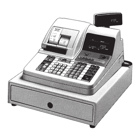
- Page 1 SERVICE MANUAL (without price) ELECTRONIC CASH REGISTER CE-3700 (EX-278) CE-3750 (EX-279) DEC, 1994 INDEX...
-
Page 2: Table Of Contents
7. CIRCUIT EXPLANATIONS ................8 8. DISASSEMBLY / ASSEMBLY METHOD ..........12 9. DIAGNOSTIC OPERATION ............... 13 10. PROGRAMMING THE CE-3700 SERIES CASH REGISTERS ....17 11. OPERATION ....................19 12. ERROR CODES ..................20 13. IC DATA ..................... 21 14. -
Page 3: Specification
Product introduction This machine CE-3700(EX-278) is a succession machine for CE-3400(EX-253). The simultaneous boot model is EX-279. EX-278: The drawer not separation type. EX-279: The drawer separation type. The Rom/Ram is the internal organs. 1. SPECIFICATION 1-1. Product 0 °C 40 °C... - Page 4 1-5. The durability specifications Switch Key board switch: 5,000,000 times Control lock: 20,000 times Operation key 100,000 times Feed switch 5,000,000 times Receipt on/off switch 10,000 times Reset switch 100,000 times Drawer: 1,000,000 times Printer MCBF: 2,000,000 line Ink roll 400,000 line Stamp Ink:...
-
Page 5: Option Specifications
2. OPTION SPECIFICATIONS 2-1. Ink roll: IR-92 2-2. Waterproofing cover: WT-70 2-3. Roll paper: P-4575 (45×12×75D) 2-4. Electric power supply for an emergency: B-6 The parts for adding B-6 are not equipped. They should be ordered separately from service department. The following parts are necessary to add B-6. -
Page 6: Initialize
4. INITIALIZE By Initialize code Init. A: The format is done of EEPROM, and, without it is read, and Init. Code is written in. Init. B: The data is read from EEPROM. 4-1. To hang initial start-up of CPU and peripheral device, and All Clear makes memory. When there is Data backed up by EEPROM, by Initialize code, to develop it on Memory top. -
Page 7: Auto/Reset Switch Initialize
4-2. Auto or Reset switch initialize Operation Display Printing 0000000000 To push Reset SW. Power on In Low batt. D1D2D3D4D5 D1 ~ D5 XXXX: Rom Control No. -- XXXX -- D1D2D3D4D5 --------------- Input value D1 ~ D5 YYMMDD 1: MMDDYY 2: DDMMYY General (Add2, DDMMYY) -
Page 8: Major Component
5. MAJOR COMPONENT UPD78044AGF080-3B9 LC36256PLL 256K bit SRam Printer Model CR812A-009-15-001A MCBF 2,000,000 lines Drawer DL-2416 D-15TC-A55SP-1* Canada DL-2351 D-15TC-A54SP-1* DL-2751 D-15TC-A84SP-1* Other Countries DL-2350 D-15TC-A54P-1* DL-2750 D-15TC-A84P-1* Germany DL-2752 D-15BC-A84S-1* CPU Pin Description Port Name Description Port Name Description FIP6 Display Digit Signal (Dg7) Receipt Common Signal... -
Page 9: Block Diagram
6. BLOCK DIAGRAM Standard Option Printer (CR812A) Main Display (10 columns) Pop-uo Display (10 columns) (32K byte) EEPROM (512 byte) Key board Drawer Multi Drawer Compulsory Drawer (USA, Canada,Germany, UK) Buzzer Power Supply Back-up battery Battery operation (Vanadium Lithium) (B-6) —... -
Page 10: Circuit Explanations
7. CIRCUIT EXPLANATIONS 7-1. Power supply circuit 1) Diodes rectification bridge By diodes rectification bridge, alternating voltage is converted into DC voltage, and the electrical voltage is done filtering of by Capacitor C4. 2) Power supply circuit for B-6 The electrical voltage which puts in resistor 3 when line voltage includes anomaly changes, and transistor Q1 becomes on status, and CS signal is done outgoing of by this, and VP... - Page 11 7-4. Reset circuit The voltage fluctuation of VDD is controlled of IC10 (S-80727AN). CPU is done Reset by pushing Reset Switch or drifting VDD. S-80727AN Reset SW Reset 7-5. Data communication between CPU and EEPROM IC11(BR93LC46A). EEPROM is Rom that write / erase is possible electrically. BR93LC46A is a non- volatile register, and serial data of 16 bit can be memorized with 64 register.
- Page 12 [ Data reading procedure ] When the CPU read the data of EEPROM, CPU send the CS signal and SK signal to EEPROM. Then CPU send the address to EEPROM, and then EEPROM return the data to CPU. Address Data Output data here [ Data writing procedure ] When the CPU save the data to EEPROM, CPU sends the CS and SK signal to EEPROM.
- Page 13 7-6. Time chart 1) RAM writing timing 16.4 us 13.6us 3.95us 1.4us 15.0us 2) RAM reading timing 18.3us 7.45us 3) EEP-ROM Writing and reading timing 29us — 11 —...
-
Page 14: Disassembly / Assembly Method
8. DISASSEMBLY / ASSEMBLY METHOD Remove the Printer cover. Upper case can remove it from by 4 places screws of printer four corners. (Lower chart 1 reference) It comes off while sliding of Upper case backward by raising it. Key board can remove it from by 4 places screws. (Lower chart 2 reference) —... -
Page 15: Diagnostic Operation
9. DIAGNOSTIC OPERATION 9-1. Start-up method By the next operation, EX-278 enters Test mode. 1) Mode switch off. 2) To continued pushing J-feed button. 3) To set the Mode switch to Program. 4) To release from the J-feed button. 5) To input 9 9 9 9 9 0 0 0 0 0 #2 Printing out 00-00-00 00:00... - Page 16 9-4. Various switch status display 0: Fixed For Taiwan 1: Journal mark sensor 0: Except it For Taiwan 1: Receipt mark sensor 0: Except it 1: Fixed Non taxable pad For Japan 0: Taxable (pat short) 1: Non-taxable (pat open) Drawer sensor 0: Open 1: Close...
-
Page 17: Print/Display/Drawer/Ram Testing
9-5. Print, Display, Drawer and Ram testing to do a various test by value number key. The following code print by all means then. 1 #2: All testing 3 #2: E PRom r/w testing 4 #2: E PRom reading testing 5 #2: Ram reading testing 96 # 96 #2:E... - Page 18 This does R/W test of testing area of E PRom during single word, and, at the time of normal, does normal termination print. Abnormal end: To do the following printing then breaking - - - - - - - 8 Receipt printing Beeping one shot buzzer on This does read only test of testing area of EEPRom during single word.
-
Page 19: Programming The Ce-3700 Series Cash Registers
10. PROGRAMMING THE CE-3700 SERIES CASH REGISTERS The Casio CE-3700 series is capable of a versatile range of features and function that give it the capability to readily adapt to almost any retail environment. The cash register is programmed at the factory with the most standard operating features and functions. - Page 20 1 Use Program 4 to read the assignment of functions to programmable keys and then make changes. 2 Use Program 3 to read the definition of machine features and key functions and then make changes. 3 Use Program 1 to read programming of time, date and unit price, amounts, rates, etc. and then make changes.
-
Page 21: Operation
These and other features and functions of the CE-3700 series electronic cash register make it a welcome addition to any retail environment. • Performing daily cash register operations The actual operations that you perform with your cash register will depend in the nature of your own business. -
Page 22: Error Codes
12. ERROR CODES Error codes appear on the display whenever you make a mistake during operation. The following table shows the actual error codes, their meanings, and the actions to take to correct the situation. Error Code Meaning Action Return the MODE switch to its original Position of MODE switch changed before E 01 setting and finalize the operation before... -
Page 23: Ic Data
13. IC DATA 1) TC74HC138 2) TC74HC174 3) TC74HC367 — 21 —... -
Page 24: Pcb Layout
14. PCB LAYOUT B-1 125V 2.5A CS VP DCSI µPC24M05 BA12003 BA12003 74HC367 IC4 BA12003 B-11 B-12 74HC367 BA12003 µPD78044 F-15 F-16 F-17 F-18 B-17 F-19 F-20 F-21 F-22 B-18 C-11 F-23 BA10393 C-15 D-12 D-13 J-14 IC10 D-14 S-80727AN D-15 D-16 C-19... -
Page 25: Circuit Diagram
TEND %– 8 13 %– SUB TOTAL PRICE MD/ST TOTAL — — 7 12 ERR.CORR ERR.CORR • • 0 00 6 11 0 00 TEND TEND CANCEL CANCEL Board No. Drawing No. BLOCK DIAGRAM for CE-3700 E240032 — 23 —... - Page 26 E278-E2-2 POWER OPTION TRANSFORMER 3PIN MODE-KEY 10PIN 12PIN 2PIN E278-E2-1 PRINTER min 1.5S 31PIN 15mS CR812A 32PIN 40mS E241 -E3-2 RECEIPT RESET SW ON/OFF 2PIN NEAR END SENSER 300mS CPU-CLK OPTION 2PIN E278-1 18PIN E278-E4 3PIN 5PIN 3PIN 3PIN KEY CLERK BATTERY DRAWER DRAWER...
- Page 27 IMSA-9604S-18C CN6 IMSA-9604S-32C 18 17 16 15 14 13 12 11 10 9 8 7 6 5 4 3 2 1 32 31 23 24 25 26 27 28 29 30 2 9 8 5 6 3 13 14 15 16 17 18 19 20 21 22 7 12 11 10 4 1 OTP ONLY TFC103 2SC945...
- Page 28 CNB5X101K CNB8X101K CNB8X101K CNB3X101K 74HC367*2 RESET SW JPM1030-0101 HBLB31-S2J BA10393 2 3 4 6 7 2 3 4 5 6 7 8 9 2 3 4 5 6 7 8 9 2 3 4 STAMP JFEED RFEED JCOM JHD1 JHD2 KEY CLERK JHD3 JHD4...
- Page 29 UPC24M05HF CRB25T29EFX1500 1S2471 T-77-T JPM1030-0201 BA12003 CR-25-56KOHM-J-T 1S2471 T-77-T BA12003 CR-25-56KOHM-J-T 1S2471 T-77-T OSH-3040-SPL BA12003 CR-25-56KOHM-J-T 1S2471 T-77-T BA12003 CR-25-56KOHM-J-T 1S2471 T-77-T DCS-278 UPD78P044GF-080 CR-25-56KOHM-J-T 1S2471 T-77-T TC74HC367AP CR-25-100OHM-J-T 1S2471 T-77-T UF-0033 TC74HC367AP CR-25-100OHM-J-T 1S2471 T-77-T 21801.6 BA10393 CR-25-100OHM-J-T 1SR35-100A-T-32-T 23702.5 IC10 S-80727AN-Z...
- Page 30 SH101MA MODE KEY SW.1 KSL-B85FA02-B1J X2/Z2 REG2 1S2471 T-77-T REG1 MODE KEY SW.2 8 7 6 5 3 2 REG1 REG2 X2/Z2 CLCOM SWI0 SWI1 SWI2 SWI3 SWI4 SWI5 MODE KEY SW.2 KSL-84FG01-B1J A,D,B,BU SWI6 PCOM 1 2 10 9 8 7 6 5 4 3 31242528273020191817161514131211262122232932 CN1 IMSA-9604S-32C Board No.
- Page 31 KEY CONTACT POSITION Board No. Board No. KEYBOARD E278-E4 E240037 — 29 —...
- Page 32 US. CANADA (US. CANADA SPEC.) EUROPE (C, L) (B, F, G) 240V 240V 230V 230V 220V 220V 120V 120V 100V 100V L5T18X6X10 L5T18X6X10 L5T18X6X10 L5T18X6X10 TE-278-E2U TE-278-E2U L5T18X6X10 L5T18X6X10 U.K. (LIMITED AREAS SPEC.) S–J2875–05 240V 240V 230V 230V 220V 220V 120V 120V 100V...
- Page 33 SH1019A CN1 IMSA-9604S-10C CN2 IMSA-9604S-12C Board No. Drawing No. 2ND DISPLAY E278-E2-2 E440039 — 31 —...
- Page 34 SWI6 R ON PCOM R OFF Board No. Drawing No. SWITCH PCB E440040 — 32 —...
-
Page 35: Parts List
16. PARTS LIST Main PCB ass'y Button ass'y E278-E2 ass'y, Display ass'y 2nd Display ass'y Upper case Lower case Printer unit Drawer 8-1. DL-2350 (Europe) 8-2. DL-2351 (Canada) 8-3. DL-2416 (U.S.A.) 8-4. DL-2750 (Japan, Germany, Europe) 8-5. DL-2751 (U.K.) 8-6. DL-2752 (Germany) Notes: 1. -
Page 36: Parts List
— 35 —... - Page 37 — 36 —...
- Page 38 — 37 —...
- Page 39 — 38 —...
- Page 40 1-04 1-05 1-07 1-28 1-29 1-10 1-21 1-02 1-03 1-06 1-08 1-09 1-30 1-32 1-01 1-31 1-13...
- Page 41 — 41 —...
- Page 42 — 42 —...
- Page 43 — 43 —...
- Page 44 — 44 —...
- Page 45 2-26 2-05 2-25 2-21 2-07 2-24 2-21 2-92 2-91 2-29 2-23 2-93 2-16 2-04 2-01 2-21 2-07 2-20 1-01 2-12 2-14 2-06 1-25 2-16 2-13 4-01 2-17 2-03 2-10 2-24 1-26 2-08 2-81 2-11 1-24 2-02 1-27 3-15 4-15 2-09 3-06 3-12 3-13...
-
Page 46: Printer Unit
— 47 —... - Page 47 — 48 —...
- Page 48 — 49 —...
- Page 49 — 50 —...
- Page 50 DL-2350 5-01 5-02 5-18 5-15 5-17 5-20 5-19 5-14 5-12 5-16 5-05 5-06 5-07 5-13 5-09 5-04 5-22 5-37 5-08 5-26 5-25 5-36 5-23 5-24 5-40 5-39 5-38 — 51 —...
- Page 51 — 52 —...
- Page 52 DL-2351 6-01 6-02 6-18 6-15 6-17 6-20 6-19 6-14 6-12 6-16 6-05 6-06 6-07 6-13 6-09 6-04 6-22 6-37 6-08 6-26 6-25 6-24 6-36 6-23 6-40 6-39 6-38 — 53 —...
- Page 53 — 54 —...
- Page 54 DL-2416 7-01 7-02 7-18 7-15 7-17 7-20 7-19 7-14 7-16 7-12 7-05 7-06 7-07 7-13 7-09 7-04 7-22 7-37 7-08 7-26 7-25 7-24 7-36 7-23 7-40 7-39 7-38 — 55 —...
- Page 55 — 56 —...
- Page 56 DL-2750 8-01 8-02 8-18 8-15 8-17 8-20 8-19 8-14 8-16 8-12 8-05 8-06 8-07 8-13 8-09 8-04 8-22 8-37 8-08 8-26 8-25 8-24 8-36 8-23 8-40 8-39 8-38 — 57 —...
- Page 57 — 58 —...
- Page 58 DL-2751 9-01 9-02 9-18 9-15 9-17 9-20 9-19 9-14 9-16 9-12 9-05 9-06 9-07 9-13 9-09 9-04 9-22 9-37 9-08 9-26 9-25 9-24 9-36 9-23 9-40 9-39 9-38 — 59 —...
- Page 59 — 60 —...
- Page 60 DL-2752 10-01 10-02 10-18 10-15 10-17 10-20 10-19 10-14 10-16 10-12 10-05 10-06 10-07 10-13 10-09 10-04 10-22 10-37 10-08 10-26 10-25 10-24 10-36 10-23 10-40 10-38 10-39 — 61 —...
- Page 61 8-11-10, Nishi-Shinjuku Shinjuku-ku, Tokyo 160, Japan Telephone: 03-3347-4926...