Table of Contents
Advertisement
Advertisement
Table of Contents

Related Manuals for Casio CE-2350


Summary of Contents for Casio CE-2350
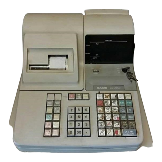
- Page 1 SERVICE MANUAL ELECTRONIC CASH REGISTER CE-2350 (EX-259) JAN. 1995 INDEX...
-
Page 2: Table Of Contents
CONTENTS 1. FEATURES......................2. SPECIFICATION ....................3. MAC (Memory All Clear) OPERATION .............. 4. DIAGNOSTIC OPERATION ................4-1. How to start ....................4-2. Mode switch and PAD status display check ............ 4-3. Hard key code check ..................4-4. Hard check function ..................5. -
Page 3: Features
1. FEATURES The differece between CE-2300 and CE-2350 is as follows; Item C E - 2 3 0 0 C E - 2 3 5 0 19 x 2 Department number (for using DEPT SHFT key) PLU number Clerk number... -
Page 4: Mac (Memory All Clear) Operation
RAM : Name : LC36256PLL Capacity : 32 KB Printer : Name : CR-710-001 Print method : Rubber-type inner-hummer printing system Receipt number : 2 receipt (Receipt & Journal) Print digit : 12 digits (Numeric : 10 digits, Symbol : 2 digits) Printing speed : Approx. -
Page 5: Diagnostic Operation
Date Time Consecutive No. MAC print Note : 1. After initialize operation, the clock counts from 00 : 00 A.M. and also the calendar is started from 00 - 00 - 00. 2. If the memory of RAM is broken, the machine will be initialized after power on. 4. -
Page 6: Mode Switch And Pad Status Display Check
4-2. Mode switch and PAD status display check When the Clear key is pressed or changing the position of mode switch, the machine displays the mode switch position. Drawer status PAD status Receipt SW position Mode SW position Drawer status : 1 : Drawer open Drawer close PAD status :... -
Page 7: Hard Check Function
20 26 32 38 43 Receipt Journal 13 14 19 25 31 37 42 FEED FEED 18 24 30 36 41 17 23 29 35 40 16 22 28 34 39 10 11 15 21 27 33 4-4. Hard check function Enter 1 digit from numeral key and press the sub total button (ST), the following Hard check function will be executed. - Page 8 5) Printing check Print the following character. 0 0 CA CD 6) Receipt issue The following receipt is issued. 7) Test display 4-4-2. RAM read only check Operation :5 + ST Note : Be sure to execute the RAM write and read check (1 + ST) before this check. The machine reads out the data to compare with written data until an error is occurred and brinks "...
- Page 9 4-4-4. All characters print check Operation : 8 + ST 4-4-5. Display the time Operation : 9 + ST The machine display the time. To stop this check, press the Clear key. 1 2 -- 3 4 The time counts up. If you make following operation, the machine resets the time data and starts again.
-
Page 10: Option Circuit
5. OPTION CIRCUIT Power protection battery B-6 Power protection battery B-6 os available fro CE-2350. However, interface circuit is not mounted the machine. When you use the B-6, mount the following parts. Parts list for interface Code No. Parts Name Specification Q’ty... -
Page 11: Circuit Explanation
6. CIRCUIT EXPLANATION 6-1. Power supply circuit Q1 : Transistor for controlling voltage (VP) Q2 : Transistor for voltage detection Q3 : Transistor for controlling power down (PWD) signal ZD2 : Zener diode for controlling base current of Q2 ZD3 : Zener diode for detecting power down (PWD) signal After plug the AC cord into the outlet, the AC voltage (23.8V) appears at CN1 connector. - Page 12 [PWD signal] After plug the AC cord into outlet, VP voltage appears on the base terminal of transistor Q3. When the VP exceeds 16 volts, Q3 is turned on by the differential voltage between base and emitter terminal of transistor Q3. Then the PWD signal goes to GND level and informes “...
-
Page 13: Cpu
6 - 2 . C P U ( u P D 7 5 5 1 6 G F - 3 5 1 - 3 B 9 ) PW-ON Pin No. Signal Descriptions In/Out level 1 AN0 Mode switch signal (RF,OFF,REG,X,Z) signal 2.0V 2 AVREF VCC terminal (+5V) -
Page 14: Motor Error Detection Circuit
PW-ON Pin No. Signal Descriptions In/Out level 51 P02/SO0/SB0 Key input signal (Ki2) High 52 P01/SCK0_ Key input signal (Ki1) High 53 P00/INT4 Key input signal (Ki0) High 54 VSS GND terminal 55 XT1 Sub system clock signal (32.768KHz) Pulse 56 XT2 Sub system clock signal (32.768KHz) Pulse... -
Page 15: Mode Key Switch Status Read
6-3. Motor error detection circuit When the CPU output motor signal, transistor Q8 becomes on and the voltage level at “A” point becomes GND. Then, paper feeding motor rotate. Normally, pin No.1 of IC4 appears low signal. IC4 detects differential voltage between pin No.2 and 3. In case pin No.3 is higher than No.2, output(Pin No.1) signal is hogh. -
Page 16: Ram Address/Head Drive Signal Switching Circuit
6-5. RAM address/head drive signal switching circuit The CPU is used the port for RAM address (A0~A11) and head drive signal (HD1~HD6). To select the RAM address and head drive signal, CPU use “STEP MOTOR COM” signal. When CPU wants to read the RAM chips, CPU stops “STEP MOTOR COM” signal. The CPU controls RAM address (A0~A12) using IC10 because of CPU has 7 ports. -
Page 17: Printer Error Condition Of Cpu
6-7: Printer error condition of CPU 1). When motor error signal comes, CPU knows printer error. 2). When reset pulse does not come within a period of time which is controlled by CPU, CPU knows printer error. Then CPU stops printing. CPU selects printing character by software. -
Page 18: Pcb Layout
8. PCB LAYOUT... -
Page 19: Circuit Diagram
- 17 -... - Page 20 - 18 -...
- Page 21 - 19 -...
- Page 22 - 20 -...
- Page 23 - 21 -...
- Page 24 - 22 -...
- Page 25 - 23 -...
- Page 26 - 24 -...
- Page 27 - 25 -...
- Page 28 - 26 -...
- Page 29 - 27 -...
-
Page 30: Parts List
PARTS LIST MODEL : CE-2350 (EX-259) CO NTE NT S 1. Main PCB ass’y ......................2. Main display block ......................3. Customer display block ....................4. Keyboard block ......................5. Button block ....................... 6. Power supply block ..................... 7. Upper case block ...................... - Page 31 1.Main PCB ass’y FOB Japan N Item Code No. Parts Name Specification Ver. N.R.Yen Unit Price MAIN PCB ASS'Y 6192 6210 Main PCB ass'y (E259-1) E211743*1 10720 A IC11 2006 0717 LSI LC36256PLL10/12/15 630 A N IC5 2006 1039 LSI UPD75516GF-585-3B9 750 A IC13...
- Page 32 FOB Japan N Item Code No. Parts Name Specification Ver. N.R.Yen Unit Price 2801 8932 Ceramic oscillator CST4.19MGW 75 A N C6 2807 2231 Electrolytic capacitor RE2-50V470M-T2 1 20 22 C N C9 2807 2238 Electrolytic capacitor RE2-50V010M-T2 1 20 13 C N C8 2807 2245 Electrolytic capacitor...
- Page 33 2. Main display block FOB Japan N Item Code No. Parts Name Specification Ver. N.R.Yen Unit Price MAIN DISPLAY BLOCK 6191 0091 E240-E2 ass'y E211153*1 3510 C 1 2320 1365 LED HDSP-5621#S02 160 A 2601 6816 Carbon film resistor ERD25TJ121V 8 20 2601 6817 Carbon film resistor ERDS2TJ121V...
- Page 34 3. Customer display block FOB Japan N Item Code No. Parts Name Specification Ver. N.R.Yen Unit Price CUSTOMER DISPLAY BLOCK 6191 0092 E240-E2 ass'y E211153*2 3510 C 7 2320 1365 LED HDSP-5621#S02 160 A 2601 6816 Carbon film resistor ERD25TJ121V 8 20 2601 6817 Carbon film resistor ERDS2TJ121V...
- Page 35 4. Keyboard block FOB Japan N Item Code No. Parts Name Specification Ver. N.R.Yen Unit Price KEYBOARD BLOCK 13 3501 5474 FFC connector 52045-2245 78 A 14 4306 1013 PCB E241-E3-2 E311071A-1 1 10 43 X (without components) 15 4308 1074 PCB E241-E4 E312009-1 380 C (without components)
- Page 36 5. Button block...
- Page 37 FOB Japan N Item C o d e N o . Parts Name Specification V e r . N . R . Y e n Unit Price BUTTON BLOCK 22 6221 0630 Coil spring A E411104-1 23 6221 0648 Coil spring B E411104-2 24 6221 3988 L cap...
- Page 38 6. Power supply block FOB Japan N Item Code No. Parts Name Specification Ver. N.R.Yen Unit Price POWER SUPPLY BLOCK 45 3000 3020 Power transformer TE-233-E4D 910 A 46 3030 4055 Ferrite core L5T18X6X10 45 X 47 3700 4281 Power cord PS204 400 C 48 5530 0526 Cable joiner...
- Page 39 7. Upper case block...
- Page 40 FOB Japan N Item Code No. Parts Name Specification Ver. N.R.Yen Unit Price UPPER CASE BLOCK 5111 2714 Screw with washer 3X20 ZMC-3.. 2 20 5112 0124 Screw with washer 3X8 ZMC-3..5 20 49 6220 2505 Display bush E310377-1 63 X 50 6221 3884 Mode cover B E210953-2...
- Page 41 FOB Japan N Item Code No. Parts Name Specification Ver. N.R.Yen Unit Price PRINTER BLOCK 59 1000 8141 Printer unit CR-710-001MA 7360 A 5150 1637 Screw 4X8 ZMC-3... 1 20 60 6191 0077 FG wire ass'y E411673*1 85 X PRINTER FIXING BLOCK 61 6000 6091 Battery spring G67 A43656-1 1 10...
- Page 42 9. Printer unit...
- Page 43 FOB Japan N Item Code No. Parts Name Specification Ver. N.R.Yen Unit Price 101 1909 1665 Derent pawl ass'y F750003000 100 X 102 1909 1666 Board ass'y A F750004000 530 X 104 1909 1667 Paper guide ass'y F750006000 650 B 105 1909 1668 Paper feed motor F750005020 930 A...
- Page 44 10. Drawer unit 10-1. DL-2417 ( for U.S.A.)
- Page 45 FOB Japan Item Code No. Parts Name Specification N.R. Yen Unit Price DL-2416 (U.S.A.) 6246 5070 Box sub ass'y E311975*1 4,330 X 6192 6330 Drawer ass'y E311955*2 2,890 C 6246 5140 Drawer label DL-2416 E311977-4 6221 4893 Rubber foot ZD01013-A 5150 1645 Screw with washer 3X5 ZMC-3...
- Page 46 10-2. DL-2351 ( for Canada)
- Page 47 FOB Japan Item Code No. Parts Name Specification N.R. Yen Unit Price DL-2351 (Canada) 6246 5070 Box sub ass'y E311975*1 4,330 X 6192 6330 Drawer ass'y E311955*2 2,890 C 6246 5150 Drawer label DL-2351 E311977-5 6221 4893 Rubber foot ZD01013-A 5150 1645 Screw with washer 3 X 5 ZMC-3...