Table of Contents
Troubleshooting

Related Manuals for Panasonic EY6803-X8


Summary of Contents for Panasonic EY6803-X8
-
Page 1: Table Of Contents
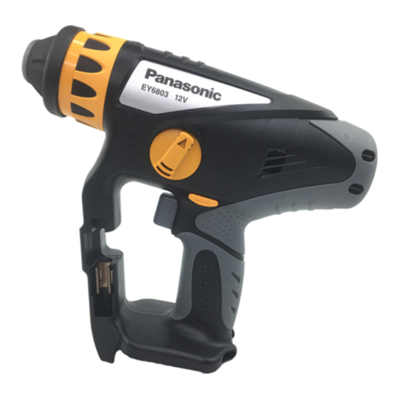
ORDER NO.PTD0606X33CE Cordless Rotary Hammer Drill & Driver EY6803-X8 SPECIFICATIONS CONTENTS Page Page 1 SCHEMATIC DIAGRAM 5 TRIAL OPERATION (after checking TROUBLESHOOTING 2 WIRING CONNECTION DIAGRAM GUIDE.) 3 DISASSEMBLY/ASSEMBLY INSTRUCTIONS 6 EXPLODED VIEW 4 TROUBLESHOOTING GUIDE 7 REPLACEMENT PARTS LIST ©... -
Page 2: Schematic Diagram
EY6803-X8 1 SCHEMATIC DIAGRAM 2 WIRING CONNECTION DIAGRAM... -
Page 3: Disassembly/Assembly Instructions
EY6803-X8 3 DISASSEMBLY/ASSEMBLY INSTRUCTIONS IHOW TO DISASSEMBLE THE MAIN UNIT. Ref. No. 1A Procedure 1A Removal of the chuck handle. 1. Set the hammering/drilling switching lever to the position 2. Pluck the chuck cover depressing the chuck handle. 3. Remove the chuck handle. - Page 4 EY6803-X8 IHOW TO DISASSEMBLE THE MOTOR AND SWITCH. Procedure 1A→ → → → 1B→ → → → 2A Ref. No. 2A Removal of the switch. 1. Take out the switch and the base plate assembly from the housing. 2. Take out the LED cover.
-
Page 5: Piston Applying Power Spring
EY6803-X8 IHOW TO DISASSEMBLE THE DRIVING BLOCK. Ref. No. 2C Procedure 2A → → → → 2B → → → → 2C Removal of the power shaft assembly. 1. Remove the piston applying power spring. 2. Take out the power shaft assembly. -
Page 6: Spindle Assembly
EY6803-X8 Ref. No. 2D Procedure 2A → → → → 2B → → → → 2C→ → → → 2D Attachment of driving block. For assembling 1. Set the jig (bearing cap) into the clutch case and hold it with a vise in order to take out the bearing. -
Page 7: Troubleshooting Guide
EY6803-X8 4 TROUBLESHOOTING GUIDE (Refer to WIRING CONNECTION DIAGRAM) 4.1. CHECK POINTS FOR ELECTRICAL PARTS. - Page 8 EY6803-X8 4.2. CHECK POINTS FOR MECHANISM BLOCK.
- Page 9 EY6803-X8...
-
Page 10: Trial Operation (After Checking Troubleshooting Guide.)
EY6803-X8 5 TRIAL OPERATION (after checking TROUBLESHOOTING GUIDE.) 5.1. HAMMER/DRILL Confirm the action when setting the H/D handle to HAMMER mode. Rotation with hammering when the drill bit touches something like stone, and power. It is OK, if it takes about 4-6 seconds by 20kgf to hole ( 6X30) on the concrete . -
Page 11: Exploded View
EY6803-X8 6 EXPLODED VIEW... -
Page 12: Replacement Parts List
EY6803-X8 7 REPLACEMENT PARTS LIST NOTE: *B=only available as set *C=available individually Ref.No. Part No. Part Name & Description Remarks Per Unit WEY6803K3079 HOUSING AB SET for EUROPE WEY6803K3070 HOUSING AB SET for OCEANIA WEY6813H3116 CHUCK COVER WEY6803K3127 CHUCK HANDLE...