Table of Contents
Advertisement
Advertisement
Table of Contents

Related Manuals for Fujitsu PRIMERGY RX300 S6


Summary of Contents for Fujitsu PRIMERGY RX300 S6
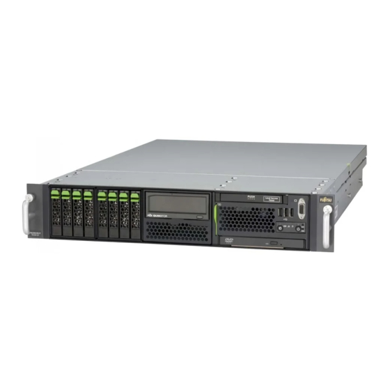
- Page 1 Operating manual - English PRIMERGY RX300 S6 Operating manual Edition March 2011...
-
Page 2: Copyright And Trademarks
– The contents of this manual may be revised without prior notice. – Fujitsu assumes no liability for damages to third party copyrights or other rights arising from the use of any information in this manual. – No part of this manual may be reproduced in any without the prior written permission of Fujitsu. - Page 3 Before reading this manual For your safety This manual contains important information for safely and correctly using this product. Carefully read the manual before using this product. Pay particular attention to the accompanying manual "Safety Notes and Regulations" and ensure these safety notes are understood before using the product.
- Page 4 (hereafter, "high safety use"). Customers should not use this product for high safety use unless measures are in place for ensuring the level of safety demanded of such use. Please consult the sales staff of Fujitsu if intending to use this product for high safety use.
- Page 5 Only for the Japanese market: Although described in this manual, some sections do not apply to the Japanese market. Operating manual RX300 S6...
- Page 6 Operating manual 300 S6...
-
Page 7: Table Of Contents
Contents Preface ......11 Concept and target groups for this manual ..11 Documentation overview . - Page 8 4.4.1 RX300 S6 to the mains ..... . 63 4.4.1.1 Connecting the power cord ....63 4.4.1.2 Using cable ties .
- Page 9 Incorrect date and time ....92 System will not boot ..... . 92 Drives reported as "dead"...
- Page 10 Appendix: server specification ....121 Index ........125 Operating manual 300 S6...
-
Page 11: Preface
The system was developed specifically for configurations with multiple servers (clusters), front-end solutions, e-commerce applications and ERP solutions. The PRIMERGY RX300 S6 is ideal for applications and operational areas that require maximum scalability, performance and availability in a space-saving rack cabinet. -
Page 12: Documentation Overview
Documentation overview Documentation overview More information on your PRIMERGY RX300 S6 can be found in the following documents: – "Quick Start Hardware - PRIMERGY RX300 S6" leaflet " はじめにお読みください -PRIMERGY RX300 S6" for the Japanese market (only included as a printed copy) –... - Page 13 Internet. The overview page showing the online documentation available on the Internet can be found using the URL (f o r EMEA market): http://manuals.ts.fujitsu.com. The PRIMERGY server documentation can be accessed using the Industry standard servers navigation option.
-
Page 14: Features
Concept - LSC" manual on the ServerView Suite DVD 2). In addition, CSS errors are displayed in the ServerView Operations Manager - the server management software from Fujitsu Technology Solutions. In the event of errors, the ServerView Operations Manager refers you directly to the affected component and its order information in the Illustrated Spares catalog of the server in question. - Page 15 Features System board The features of the system board (D2619-N) are described in the technical manual for the system board in relation to the hardware and in the BIOS setup manual. USB Flash Module (UFM) (option) The system board is equipped with a UFM slot by the manufacturer. The "internal USB stick"...
- Page 16 Features Fujitsu Technology Solutions offers a unique patented solution to deliver the highest possible bandwidth with four PCIe Gen2 x8 slots: two of the four PCIe Gen2 x4 slots can each be used as PCIe Gen2 x8 slots if the neighboring slot is free.
- Page 17 Features Hard disk drives The server is available in the following drive configurations: 6*3.5-inch SAS/SATA hard disk drives: up to si x (2x3) HDD modules, each with a 3.5- i nch SAS/SATA hard disk drive with a maximum height of 1 inch. Slot for an optional 3.5-inch DAT or RDX drive.
- Page 18 Features The module is connected to the SAS/SATA backplane without cables. This allows HDD modul e s to be simply plugged in or pul l ed out (for further details see section "Hot-plug disk drives" on page 100). The hard disk subsystem is designed for SAS/SATA, each with one channel for each hard disk drive.
- Page 19 Features Further information on other SAS/SATA RAID controllers (e.g. for operating external SAS/SATA hard disk drives or tape drives) is available on ServerView Suite DVD 2 under Industry Standard Servers - Expansion Cards - Storage Adapters - LSI RAID / SCSI Controllers. Accessible drives/components A number of mounting locations are available: –...
- Page 20 Features Power supply In its basic configuration, the server has a hot-pluggable power supply unit that adjusts automatically to any power voltage in the range from 100 V to 240 V. As an option, the power supply can be expanded with an extra power supply unit to create a redundant power supply.
- Page 21 "hides" the defective system components. The PDA (Prefailure Detection and Analysing) technology from Fujitsu analyzes and monitors all components that are critical for system reliability. The RAID functionality of the SAS RAID controller supports RAID levels 0, 1, 10, 1E, 5, 50, 6 und 60 and increases the availability of the system.
- Page 22 Features iRMC S2 with integrated management LAN connector The features of the iRMC S2 Advanced Video Redirection and Remote Storage are available as an option. The iRMC S2 (integrated Remote Management Controller) is a BMC with integrated management LAN connector and expanded functionality that was previously only available with additional plug-in cards.
- Page 23 Server management i s implemented using the ServerView Operations Manager supplied and the PDA (Prefailure Detection and Analysis) technology from Fujitsu. PDA reports the threat of a system error or overload at an early stage, allowing preventive measures to be taken.
- Page 24 BIOS update. With the iRMC S2 (integrated Remote Management Controller) on the system board, the PRIMERGY RX300 S6 server can also be maintained and serviced remotely. This enables remote diagnosis for system analysis, remote configuration and remote restart should the operating system or hardware fail.
-
Page 25: Notational Conventions
ServerView Remote Management ServerView Remote Management is the remote management solution from Fujitsu for PRIMERGY servers. ServerView Remote Management and the relevant hardware components integrated on the system board allow remote monitoring and maintenance as well as fast restoration of operation in the event of errors. -
Page 26: Technical Data
Technical data Technical data Electrical data (hot-plug power supply unit) Rated voltage range 100 V - 240 V Frequency 50 Hz - 60 Hz Rated current with basic configuration 4.2 A - 1.4 A / 100 V - 240 V Max. - Page 27 Technical data Compliance with regulations and standards Product safety IEC 60950-1/2, EN 60950-1/2, UL/CSA 60950-1/2, CNS 14336 / GB 4943 / EN 50371 Ergonomics IK1 ITB2000:2009 Electromagnetic FCC class A compatibility CNS 13438 class A, VCCI class A AS/NZS CISPR 22 class A / GB 9254 class A GB 17625, KN22 interference EN 55022 class A, EN 300386, KN29...
- Page 28 Technical data Mechanical values Width 482.4 mm Depth 770 mm Height 85.9 mm or 2HU Installation depth in rack 735 mm Cable depth in rack 100 mm (1000 mm rack recommended) Weight Approx. 25 kg (depending on configuration). Ventilation clearance At least 200 mm on the front and rear.
-
Page 29: Installation Steps, Overview
Installation steps, overview This chapter contains an overview of the steps necessary to install your server. Links take you to sections where you can find more detailed information about the respective steps: Ê First of all , carefully read the safety instructions in "Important information"... - Page 30 Ê Configure the server and install the desired operating system and applications. The following options are available: – Remote installation with the ServerView Installation Manager: With the ServerView Suite DVD 1 provided, you can configure the server and install the operating system in a convenient manner. Details on how to operate the ServerView Installation Manager, as well as some additional information, are included in the "ServerView Suite Installation Manager"...
-
Page 31: Important Information
Important information In this chapter you will find essential information regarding safety when working on your server. Safety instructions The following safety instructions are also provided in the manual "Safety Notes and Regulations" or " 安全上のご注意 ". This device meets the relevant safety regulations for IT equipment. If you have any questions about whether you can install the server in the intended environment, please contact your sales outlet or our customer service team. - Page 32 Safety instructions Before starting up CAUTION! During installation and before operating the device, observe the instructions on environmental conditions for your device. If the device is brought in from a cold environment, condensation may form both inside and on the outside of the device. Wait until the device has acclimatized to room temperature and is absolutely dry before starting it up.
- Page 33 Safety instructions CAUTION! Ensure that the power sockets on the device and the properly grounded power outlets are freely accessible. The On/Off button or the main power switch (if present) does not isolate the device from the mains power supply. To disconnect it completely from the mains power supply, unplug all network power plugs from the properly grounded power outlets.
- Page 34 Safety instructions CAUTION! Proper operation of the system (in accordance with IEC 60950-1/2 resp. EN 60950-1/2) is only ensured if the casing is completely assembled and the rear covers for the installation slots have been fitted (electric shock, cooling, fire protection, interference suppression).
- Page 35 Safety instructions CAUTION! Install the screw removed during installation/detaching Internal Options in former device/position. To use a screw of the different kind causes a breakdown of equipment. The installation indicated on this note is sometimes changed to the kind of possible options without notice. Batteries CAUTION! Incorrect replacement of batteries may lead to arisk of explosion.
- Page 36 Safety instructions Working with CDs/DVDs/BDs and optical drives When working with devices with optical drives, these instructions must be followed. CAUTION! Only use CDs/DVDs/BDs that are in perfect condition, in order to prevent data loss, equipment damage and injury. Check each CD/DVD/BD for damage, cracks, breakages etc. before inserting it in the drive.
- Page 37 Safety instructions Do not contaminate the CD/DVD/BD surface with fingerprints, oil, dust, etc. If dirty, clean with a soft, dry cloth, wiping from the center to the edge. Do not use benzene, thinners, water, record sprays, antistatic agents, or silicone-impregnated cloth. Be careful not to damage the CD/DVD/BD surface.
- Page 38 Safety instructions Modules with Electrostatic-Sensitive Devices Modules with electrostatic-sensitive devices are identified by the following sticker: Figure 5: ESD label When you handle components fitted with ESDs, you must always observe the following points: Switch off the system and remove the power plugs from the power outlets before installing or removing components with ESDs.
-
Page 39: Energy Star
ENERGY STAR Other important information: When cleaning the device, please observe the relevant notes in section "Cleaning the server" on page Keep this operating manual and the other documentation (such as the Technical Manual, DVD) close to the device. All documentation must be included if the equipment is passed on to a third party. -
Page 40: Fcc Class A Compliance Statement
Consult the dealer or an experienced radio/TV technician for help. Fujitsu is not responsible for any radio or television interference caused by unauthorized modifications of this equipment or the substitution or attachment of connecting cables and equipment other than those specified by Fujitsu. The correction of interferences caused by such unauthorized modification, substitution or attachment will be the responsibility of the user. -
Page 41: Transporting The Server
Transporting the server Transporting the server CAUTION! Only transport the server in its original packaging or in packaging that protects it from impacts and jolts. Do not unpack the server until it is at its installation location. If you need to lift or transport the server, ask other people to help you. Never lift or carry the device by the handles on the front panel. -
Page 42: Notes On Installing The Server In The Rack
Notes on installing the server in the rack Notes on installing the server in the rack CAUTION! For safety reasons, at least two people are required to install the server in the rack because of its weight and size. (For the Japanese market, please refer to " 安全上の注意およびその 他の重要情報... -
Page 43: Environmental Protection
Environmental protection Environmental protection Environmentally-friendly product design and development This product has been designed in accordance with the Fujitsu standard for "environmentally friendly product design and development". This means that key factors such as durability, selection and labeling of materials, emissions, packaging, ease of dismantling and recycling have been taken into account. - Page 44 Details regarding the return and recycling of devices and consumables within Europe can also be f o und in the "Retur ning used devices" manual, via your local Fujitsu branch or from our recycling center in Paderborn: Fujitsu Technology Solutions...
-
Page 45: Hardware Installation
Hardware installation CAUTION! Follow the safety instructions in the chapter "Important information" on page Do not expose the server to extreme environmental conditions (see "Technical data" on page 26). Protect the server from dust, humidity and heat. Make sure that the server is acclimatized for the time indicated in this table before putting it into operation. -
Page 46: Unpacking The Server
Unpacking the server Unpacking the server CAUTION! Follow the safety instructions in "Important information" on page The server must always be lifted or carried by at least two people. (For the Japanese market, please refer to " 安全上の注意 ".) Do not unpack the server until it is at its installation location. Ê... -
Page 47: Installing/Removing The Server In/From The Rack
4.2.1 Rack system requirements The rack systems from Fujitsu PRIMECENTER Rack, DataCenter Rack and 19-inch standard rack (for the Japanese market) support the installation of PRIMERGY servers. Installation in most current rack systems from other manufacturers (3rd party racks) is also supported. - Page 48 Installing/removing the server in/from the rack For PRIMECENTER Racks and DataCenter Racks: The mounting of the rails in the different racks is described in the next sections. Installation of the cable management is described in detail in the Technical Manual for the respective rack. For 19-inch standard rack (for the Japanese market): For information on mounting of the rails in the 19-inch standard rack (for the Japanese market) please refer to the "Rack mount guide".
- Page 49 Installing/removing the server in/from the rack +/- 1,6mm Figure 6: Mechanical requirements Operating manual RX300 S6...
-
Page 50: Installation In Primecenter/Datacenter Rack
Installing/removing the server in/from the rack – You must ensure that the safety mechanisms on the server, e.g. stoppers or retaining systems, are functioning correctly. – The shape of the rack support uprights must ensure that the support systems can be bolted to the front. The support systems have a li n ear alignment feature to ensure that they can be adjusted to different rack depths. - Page 51 Installing/removing the server in/from the rack Fitting the support bracket When mounting the left support system in the corresponding rack, the supplied support bracket must first be mounted flush with the underside of the device on the rear left support upright. Figure 7: Fitting the support bracket Ê...
- Page 52 Installing/removing the server in/from the rack Removing the outer telescopic rail Figure 8: Removing the outer telescopic rail Ê Extend the telescopic rail fully (1). Ê Unlock the outer telescopic rail and remove it. With fully-extendable rails (a): Press the locking lever to release the server rail.
- Page 53 Installing/removing the server in/from the rack Installing the support systems Figure 9: Fit the left support system in the PRIMECENTER/DataCenter rack Ê Position the left support system in the support bracket (insert retaining bolts) - see (1). Ê Clamp the left-hand support system (2) between the front left support upright and the support bracket by pressing the support system together, positioning it on the front support upright and releasing it again.
- Page 54 Installing/removing the server in/from the rack Ê Insert (3) the safety lock into the easy lock (snap fit). CAUTION! Ensure that the safety lock has been inserted before the server is inserted! Ê Repeat the above steps for the right-hand support system (with the front and rear right support uprights).
- Page 55 Installing/removing the server in/from the rack Preparing the server For the Japanese market: Refer to the "Rack Mounting Guide" for more detailed explanation and for other support systems. Figure 11: Preparing the server Ê Place the outer telescopic rails on the sides of the server (see arrow 1 in figure 11).
- Page 56 Installing/removing the server in/from the rack Inserting the server For the Japanese market: Refer to the " Rack Mounting Guide" for more detailed explanation and for other support systems. Figure 12: Inserting the server CAUTION! Ensure that the safety lock has been inserted before the server is inserted (see figure 9 on page 53).
-
Page 57: Installation In 3Rd Party Racks
4.2.3 Installation in 3rd party racks The support systems from Fujitsu are suitable for use in any 3rd party racks for standard servers (installation depth 714 - 785 mm) without restrictions. Ê Refer to the manual from the rack manufacturer for details of the mechanical installation and the climatic conditions. - Page 58 Installing/removing the server in/from the rack Racks with installation depth of 735 mm The lengths of the telescopic rails do not need to be adjusted with respect to each other for the installation in rack systems with 735 mm installation depth. Ê...
-
Page 59: Installation In A Telecommunication Rack With 48 Vdc Power
4.2.4 Installation in a telecommunication rack with 48 V DC power The support systems from Fujitsu are suitable for use in any 3rd party racks for standard servers (installation depth 714 - 785 mm) without restrictions. Ê Refer to the manual from the rack manufacturer for details of the mechanical installation and the climatic conditions. -
Page 60: Connecting Devices To The Server
Connecting devices to the server Connecting devices to the server The connectors for external devices are on the front and rear of the server. The additional connectors available on your server depend on the expansion cards installed. For further information refer to the "Options Guide". RX300 S6 Figure 13: Connection panel on the rear Serial connector COM2 (turquoise) 5... - Page 61 Connecting devices to the server RX300 S6 CG Figure 14: Connection panel on the rear CG variant Serial connector COM2 (turquoise) 5 Service LAN connector Serial connector COM1* (turquoise) 6 System LAN connector (LAN 2) Video connector (blue) Shared LAN connector (LAN 1) USB connectors (black) The serial interface COM1 can be used as the standard interface or for communication with iRMC S2.
- Page 62 Connecting devices to the server Three additional USB connectors (1) are located on the front of the server (figure 15): 1 1 1 Figure 15: Front side: additional USB connectors If components with large power requirements (e.g. external USB hard disk drives) are connected simultaneously, these USB connectors may be switched off.
-
Page 63: Connecting The Server To The Power Source
Connecting the server to the power source Connecting the server to the power source In its basic configuration level the server has a hot-plug power supply unit. A second hot-plug power supply unit can be added to ensure a redundant power supply. -
Page 64: Using Cable Ties
Connecting the server to the power source A phase redundancy in the power supply of the server can be set up if two hot-plug power supply units are installed. In this case, each of the power supply units is either connected to two different phases or to two separate circuits of the internal power supply network. -
Page 65: Rx300 S6 Cg To The Direct Current
Connecting the server to the power source 4.4.2 RX300 S6 CG to the direct current 4.4.2.1 Connecting the power cord Figure 18: Connecting the server to the dc voltage Ê Connect the power cable with connector to the power supply unit of the server (1). -
Page 66: Notes On Connecting/Disconnecting Cables
Notes on connecting/disconnecting cables Notes on connecting/disconnecting cables CAUTION! Always read the documentation supplied with the device you wish to connect. Never connect, or disconnect cables during a thunderstorm. Never pull on a cable when disconnecting it. Always take hold of the cable by the plug. -
Page 67: Starting Up And Operation
Starting up and operation CAUTION! Please note the safety instructions in chapter "Important information" on page 31 Controls and indicators 5.1.1 Front of server Figure 19: Front side: indicators and controls 1 3 x USB connectors Global Error indicator 2 Video connector (VGA) (option) CSS indicator 3 Reset button ID indicator / ID button... -
Page 68: Control Elements
Controls and indicators 5.1.1.1 Control elements On/Off button When the system is switched off, it can be switched on again by pressing the On/Off button. When the system is operating, pressing the On/Off button will switch off the system. The On/Off button does not disconnect the server from the mains voltage. -
Page 69: Indicators On The Control Panel
Controls and indicators 5.1.1.2 Indicators on the control panel Power-on indicator (two colors) Lights up green when the server is switched ON. Lights up orange when the server is switched OFF, but mains voltage is present (standby mode). Hard disk activity indicator (green) Lights up green when an internal drive (HDD or backup drive) is being accessed. - Page 70 Controls and indicators CSS indicator (yellow) – Lights up yellow if a prefailure event was detected for a CSS component that you can fix yourself (for reasons of precaution) with the CSS concept. – Flashes yellow if an error was detected that you can fix yourself with the CSS concept.
-
Page 71: Indicators On The Drives
Controls and indicators 5.1.1.3 Indicators on the drives DVD drive activity indicator Lights up green when the storage medium is being accessed. Hard disk drive indicators Figure 20: Indicators on the 3.5 inch and 2.5 inch HDD modules 1 LED HDD BUSY green –... - Page 72 Controls and indicators Solid state disk indicators Figure 21: Indicators on the SSD modules 1 LED BUSY green – Lights up: SSD in active phase – Does not light: SSD inactive (drive inactive) 2 LED FAULT (orange) orange (in conjunction with a RAID controller) –...
-
Page 73: Rear Of Server
Controls and indicators 5.1.2 Rear of server CSS, Global Error and ID indicators Figure 22: Indicators on the connection panel: Global Error/CSS/ID indicator Global Error/CSS/ID indicator (orange, yellow and blue) Global Error indicator (orange) – Lights up orange if a prefailure event has been detected that requires (precautionary) service intervention. - Page 74 Controls and indicators CSS indicator (yellow) – Lights up yellow if a prefailure event was detected for a CSS component that you can fix yourself (for reasons of precaution) with the CSS concept. – Flashes yellow if an error was detected that you can fix yourself with the CSS concept.
- Page 75 Controls and indicators LAN indicators 1 2 3 4 Figure 23: Indicators on the connection panel: LAN indicators Steady green signal when a LAN connection exists. link/transfer Remains dark when no LAN connection exists. (service LAN) Flashes green when LAN transfer takes place. LAN speed Steady green signal in the event of a LAN transfer rate (service LAN)
- Page 76 Controls and indicators Indicators on the hot-plug power supply unit 100 V - 240 V Figure 24: Indicator on hot-plug power supply unit Indicator on hot-plug power supply unit (two colors) Flashes green when the server is switched off, but mains voltage is present (standby mode).
- Page 77 Controls and indicators Indicators on the hot-plug power supply unit 40.5 V - 57 V Figure 25: Indicator on hot-plug power supply unit Indicator on hot-plug power supply unit (two colors) Flashes green when the server is switched off, but primary DC voltage is present (standby mode).
-
Page 78: Indicators Of The Hot-Plug Fans
Controls and indicators 5.1.3 Indicators of the hot-plug fans A status indicator (LED on the system board) is assigned to each fan. The status indicators are not visible unless the housing is open. The respective LED is set with commands in Server Management. LED (orange) Meaning does not light up... -
Page 79: Switching The Server On And Off
"Safety Precautions". When operating the device outside of this operating environment, the server may operate improperly, damage data etc. Furthermore, Fujitsu cannot be held responsible for any related damage, malfunction, or loss of data, etc. Be sure to wait for 10 seconds or more after shutdown before turning the server on. - Page 80 Switching the server on and off – System already installed: Ê Press the On/Off button (item 7 in figure 19 on page 67). The server is switched on, performs a system test and boots the operating system. In the case of configurations with a large memory size, the boot process may be prolonged and the screen may remain dark for about 20 seconds.
- Page 81 Switching the server on and off – Power button override The system can be switched off (hard power off) by holding down the On/Off button (approximately 4 - 5 seconds). CAUTION! There is a risk that data may be lost. –...
-
Page 82: Configuring The Server
Configuring the server Configuring the server This section contains information about configuring the server and installing the operating system. 5.3.1 Configuring the SAS/SATA RAID controller The server has a SAS/SATA RAID controller with "Integrated Mirroring Enhanced" functionality or "MegaRAID functionality". You can configure the SAS/SATA RAID controller either before or during installation with the ServerView Installation Manager. -
Page 83: Configuring The Server And Installing The Operating System With The Serverview Installation Manager
Configuring the server 5.3.2 Configuring the server and installing the operating system with the ServerView Installation Manager Using the ServerView Installation Manager on the ServerView Suite DVD 1 provided, you can conveniently configure the server and install the operating system. This includes configuring the server-specific settings using the ServerView Configuration Manager and configuring the RAID controller using the ServerView RAID Manager. -
Page 84: Configuring The Server And Installing The Operating System Without The Serverview Installation Manager
Configuring the server 5.3.3 Configuring the server and installing the operating system without the ServerView Installation Manager Configuring SAS/SATA RAID controller with "Integrated Mirroring Enhanced" Configure the controller as described in section "Configuring the SAS/SATA RAID controller" on page Configuring SAS/SATA RAID controller with "MegaRAID functionality" Configure the controller as described in section "Configuring the SAS/SATA RAID controller"... -
Page 85: Cleaning The Server
Cleaning the server Cleaning the server CAUTION! Switch the server off and disconnect the power plugs from the properly grounded power outlets. Do not clean any interior parts yourself; leave this job to a service technician. Do not use any cleaning agents that contain abrasives or may corrode plastic. - Page 86 Cleaning the server Operating manual 300 S6...
-
Page 87: Property And Data Protection
Property and data protection The rack model is protected against unauthorized access by a lockable rack door. To protect your system and data internally against unauthorized access, you can use the BIOS Setup security functions. BIOS Setup security functions The Security menu in BIOS Setup offers various options for protecting your data from unauthorized access. - Page 88 BIOS Setup security functions Operating manual 300 S6...
-
Page 89: Troubleshooting And Tips
Troubleshooting and tips CAUTION! Follow the safety instructions in the "Safety notes and regulations" manual or " 安全上のご注意 " and in chapter "Important information" on page If a fault occurs, attempt to resolve it using the measures described: – in this chapter, –... -
Page 90: Server Switches Itself Off
Server switches itself off Server switches itself off Server Management has detected an error Ê Check the error list of System Event Log i n ServerView Operations Manager or in the iRMC S2 web interface, and attempt to eliminate the error. Screen remains blank Monitor is switched off Ê... -
Page 91: Flickering Stripes On Monitor Screen
Flickering stripes on monitor screen Flickering stripes on monitor screen CAUTION! Switch off the server immediately. Risk of damaging the server. Monitor does not support the set horizontal frequency Ê Find out which horizontal frequency your monitor screen supports. You will find the horizontal frequency (also known as line frequency or horizontal deflection frequency) in the documentation for your monitor. -
Page 92: Incorrect Date And Time
Incorrect date and time Incorrect date and time Ê Set the date and time in the operating system or in the BIOS Setup under the Main menu, using System Date and System Time respectively. Note that the operating system may affect the system time. For example, the operating system time may deviate from the system time under Linux, and would overwrite the system time in the default setting on shutdown. -
Page 93: Added Drive Reported As Defective
Added drive reported as defective Added drive reported as defective RAID controller is not configured for this drive The drive was probably installed when the system was switched off. Ê Reconfigure the RAID controller for the drive using the corresponding utility. Information is provided in the documentation for the RAID controller. -
Page 94: No Effect Of Keyboard Or Mouse
No effect of keyboard or mouse The above log is output or the above notification is issued by ServerView when the ambient temperatureis within 30 to 35°C, which is near theupper limit of the temperature boundaries (10 to 35°C). This is to notify the administrator before the ambient temperature actually exceeds the range of the temperature boundaries. -
Page 95: Css Components
Suite Local Service Concept - LSC" manual on the ServerView Suite DVD 2. For the latest information on optional products provided for the RX300 S6 see the configurator of the server: http://ts.fujitsu.com/products/standard_servers/index.htm (for the EMEA market) http://primeserver.fujitsu.com/primergy/system.html (for the Japanese market) CAUTION! Do not disassemble the power supply unit. -
Page 96: Hot-Plug Components
Hot-plug components In the PRIMERGY RX300 S6 server, the following components are considered to be CSS components: – Hot-plug components – Hot-plug power supply units – Hot-plug hard disk drives – Hot-plug fan modules You can expand or replace the hot-plug components during operation. -
Page 97: Removing Dummy Module
Hot-plug components CAUTION! Areas around the power supply unit may remain extremely hot after shutdown. Wait for a while after shutdown before removing the power supply unit. When installing the power supply unit, be sure to confirm that the connector of the PSU is not damaged or bent. Do not insert your hands in the power supply unit slot when removing the power supply unit. -
Page 98: Replacing The Hot-Plug Power Supply Unit
Hot-plug components 8.1.1.3 Replacing the hot-plug power supply unit CAUTION! Before replacing a non defective power supply unit in a non-redundant configuration (only one power supply unit present) the server must be switched OFF. Ê Remove the cable from the installed power supply unit. 100 - 240 AC power supply Figure 26: Unlocking and removing the power supply unit Operating manual... - Page 99 Hot-plug components 40.5 - 57 DC power supply Figure 27: Unlocking and removing the power supply unit Ê Push the green catch in the direction of the arrow (1) while pulling the power supply unit out of its mounting location (2) by the handle. Grip the handle while pulling the power supply.
-
Page 100: Hot-Plug Disk Drives
8.1.2 Hot-plug disk drives The disk drives which can be ordered for the PRIMERGY RX300 S6 are supplied already mounted in an installation frame so that defective disk drives can be replaced and new hard disk drives can be added during operation. The disk drive and installation frame together make up the disk drive module. -
Page 101: Inch Hdd Module And Dummy Module
Hot-plug components Do not use the unit in e xtremely hot or cold locations, or locations with extreme temperature changes. Never attempt to disassemble a hard disk unit. 8.1.2.1 3.5-inch HDD module and dummy module Figure 28: 3.5-inch HDD module and dummy module Dummy module Tabs for unlocking the dummy module HDD module (installation frame with hard disk drive installed) -
Page 102: Inch Hdd Module And Dummy Module
Hot-plug components 8.1.2.2 2.5-inch HDD module and dummy module Figure 29: 2.5-inch HDD module and dummy module Dummy module Tabs for unlocking the dummy module HDD module (installation frame with hard disk drive installed) Indicators HDD Busy (LED green) HDD Fault (LED orange) For description see section "Hard disk drive indicators"... -
Page 103: Inch Ssd Module
Hot-plug components 8.1.2.3 2.5-inch SSD module Figure 30: SSD module Indicators Busy (LED green) Fault (LED orange) For description see section "Hard disk drive indicators" on page Handle for locking and unlocking the HDD module Button for locking and unlocking the handle Recess for applying a sticker with the current drive name and drive size SSD module (installation frame with SSD installed) Operating manual... -
Page 104: Handling Drives And Hdd/Ssd Modules
Hot-plug components 8.1.2.4 Handling drives and HDD/SSD modules Drives incorporated in the HDD/SSD modules are highly sensitive electromagnetic devices and must be handled with great care. Incorrect handling can cause partial or total failure of the drives. These failures can result in data errors and to a loss of data or to total corruption of the drive. -
Page 105: Removing/Installing The Dummy Module
Hot-plug components 8.1.2.5 Removing/installing the dummy module Free slots are provided with dummy modules. Remove the dummy module before installing an additional HDD module. Figure 31: Removing/installing the dummy module (example: 3.5-inch dummy module) Ê Press both tabs on the dummy module together until the locking mechanism disengages (1). -
Page 106: Installing The Disk Drive Module
Hot-plug components 8.1.2.6 Installing the disk drive module Unlocking the disk drive module Figure 32: Unlocking the 3.5-inch HDD and 2.5-inch HDD/SSD modules Ê Release the locking mechanism by pressing the locking button (1). Ê Push the handle of the disk drive module fully in the direction of the arrow (2). - Page 107 Hot-plug components Installing the disk drive module Figure 33: Installing the 2.5-inch and 3.5-inch HDD/SSD modules Ê Unlock the disk drive module as described in section "Unlocking the disk drive module" on page 106. Ê Carefully push the disk drive module into the empty slot (1) until it stops. Ê...
-
Page 108: Removing The Disk Drive Module
Hot-plug components 8.1.2.7 Removing the disk drive module CAUTION! Only remove a disk drive module during operation if the drive is not currently being accessed. Observe the control LEDs for the corresponding disk drive modules (see "Hard disk drive indicators" on page 71). -
Page 109: Replacing The Hot-Plug Fan Modules
The housing cover must not remain open for longer than 5 minutes. The PRIMERGY RX300 S6 server with a 48 V DC power supply is equipped with 10 fans. Do not remove one fan without replacing it. -
Page 110: Replacing The Fan Modules
Hot-plug components 8.1.3.1 Replacing the fan modules Ê Remove the housing cover (see section "Opening/closing the housing" on page 119). Figure 34: Arrangement of fans and the corresponding indicators Ê Use the indicator (lights up orange) to identify the defective fan. The position of the indicators is shown by arrows in figure Operating manual... - Page 111 Hot-plug components Figure 35: Removing the fans (example: fan 1) Ê Pull the green lever on the fan handle in the direction of the arrow (1) to release the locking mechanism, and pull out the handle (2). Ê Pull the fan out of its mounting location by its handle. Ê...
-
Page 112: Non-Hot-Plug Components
Non-hot-plug components The new fans are measured with explicit commands in Server Management. Depending on the result, the corresponding LED (see figure 34 on page 110) is set to dark (fan is in order) or orange flashing (failure) or orange lighting (prefailure). Ê... - Page 113 Non-hot-plug components If the memory module has not been correctly inserted, it may cause a fire. Insert the memory module with attention to its direction. If a memory module is installed and you pull the lever strongly outwards, the memory module pops up. Doing so may cause a device failure.
-
Page 114: Replacing A Memory Module
Non-hot-plug components 8.2.1 Replacing a memory module Ê Remove the housing cover (see section "Opening/closing the housing" on page 119). The slots for the memory modules can be found under the air duct. 8.2.1.1 Removing the air duct Figure 36: Removing the air duct If you have installed an SAS/SATA RAID controller with a BBU: pay attention to the BBU cable when lifting off the air duct! If you want to remove the air duct from the server completely, first disconnect the BBU... -
Page 115: Removing A Defective Memory Module
Non-hot-plug components 8.2.1.2 Removing a defective memory module Figure 37: Removing a memory module Ê Press the holders on either side of the mounting location concerned outward (1). Ê Pull the memory module out of the slot (2). 8.2.1.3 Installing a new memory module CAUTION! Please note the equipping rules in the technical manual for the system board D2619-N. -
Page 116: Replacing The Air Duct And Closing The Server
Non-hot-plug components 8.2.1.4 Replacing the air duct and closing the server Ê Insert the air duct in the server. If an SAS/SATA RAID controller is installed and you disconnected the BBU cable when you removed the air duct: Ê Connect the BBU cable that you disconnected previously. Ê... -
Page 117: Replacing An Expansion Card
Ê Loosen the screw on the rear cover (see circle). Ê Remove the defective expansion card from the server (see arrows). For the installing order see the configurator provided for the RX300 S6: http://ts.fujitsu.com/products/standard_servers/index.htm (for the EMEA market) for the Japanese market http://primeserver.fujitsu.com/primergy/system.html... - Page 118 Non-hot-plug components Figure 40: Installing an expansion card Ê Carefully press the new expansion card into the correct slot on the system board (arrows) until it clicks into place. Ê Secure the expansion card with the screw (circle). Ê If necessary, reconnect the cables to the expansion card and other components.
-
Page 119: Opening/Closing The Housing
Opening/closing the housing Opening/closing the housing CAUTION! The safety instructions in chapter "Important information" on page 31 must be obeyed without fail. CAUTION! The housing cover must be replaced as soon as possible for purposes of cooling, to comply with EMC regulations (regulations regarding electromagnetic compatibility) and to prevent fires. - Page 120 Opening/closing the housing Operating manual 300 S6...
- Page 121 Appendix: server specification This section explains the specifications for the server. The specifications for this server are liable to be updated without any notice. Please be forewarned. System Board System board type D2619-N Chipset Intel 5520 Processor Processor quantity and 1or 2 Intel Xeon processors type Memory Modules Configuration...
- Page 122 Serial 2 (9-pin) 1 x serial RS-232-C LAN / Ethernet (RJ-45) 2 x Gbit/s Ethernet Service LAN (RJ45) 1 x dedicated service LAN connector for iRMC S2 (10/100 Mbit/s) Service LAN traffic can be switched to shared onboard Gbit LAN port Onboard or integrated controllers RAID Controller Modular RAID 0/1 controller with "Integrated...
- Page 123 Slot notes slot 5 and 7 are notched at the right side and thus also usable for x16 cards (operating x8, slot 5 only if neighbor slot is empty) Drive bays Hard disk bay 6x 3.5-inch, for SAS / SATA or configuration 8x 2.5-inch, 12x 2.5-inch for SAS/SATA/SSD optional Accessible drive bays...
- Page 124 Weight Weight up to 25 kg Weight notes Weight may vary depending on actual configuration Rack mounting kit Rack mounting kit as option Dimensions (Base unit specific) Rack (W x D x H) 482.4 x 770 (with handles) x 85.9 mm Mounting Depth Rack 735 mm Environmental...
- Page 125 Index connectors 3rd party rack COM1 60, installing in service LAN connector 60, requirements shared LAN connector 60, system LAN connector 60, USB connector 60, accessible drives video connector 60, consumables DVD writer control panel magnetic tape drive controls acclimatization time 45, cooling Advanced Video Redirection fans...
- Page 126 screen shows flickering electrical data stripes electromagnetic compatibility 27, system does not boot electrostatic-sensitive devices FCC statement (ESD) features EMC directive flash EPROM EMC regulations 105, ENERGY STAR Global Error indicator 67, 69, environment class graphics card environmental conditions environmental protection error hard disk activity indicator 67, drifting display on monitor...
- Page 127 DVD drive activity 67, Global Error 67, 69, NMI button 67, hard disk activity 67, noise level ID 67, 70, notational conventions on power supply unit 76, on the server On/Off button 67, operation online replacement system error 69, opening information, additional housing installing...
- Page 128 correcting faults rack data protection requirements dimensions RAID controller is not configured for electrical data this drive environmental conditions recycling devices fitting in rack redundancy hot-plug power supply unit fans indicators power supply installing 47, regulations and standards LAN connector 60, Remote Storage NMI button removing...
- Page 129 startup server support bracket switch off time, defining switch on time, defining switching off, server switching on, server system fans system board PRIMERGY Diagnostic LED system does not boot system fans redundant target group technical data time, incorrect tips touch point service transport damage 29, transporting the server...
- Page 130 Operating manual 300 S6...