Honda P/N 08E51-S01-101F Installation Instructions Manual
2000 civic 2/3/4-door (dx/cx models only)
Hide thumbs
Also See for P/N 08E51-S01-101F:
- Installation instructions manual (8 pages) ,
- Installation instructions manual (8 pages)
Advertisement
Quick Links
INSTALLATION
INSTRUCTIONS
PARTS LIST
Security System (sold separately):
P/N 08E51-S01-101F
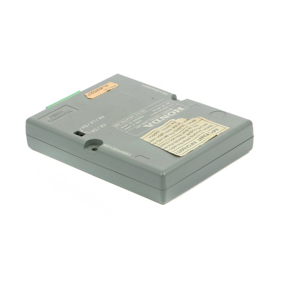
Control unit
Owner's Manual
(discard)
2 Washer-screws
(not used)
Relay 4-pin
Relay 5-pin
2 Fuses (3A)
(not used)
2 Long wire ties
(not used)
Card
(not used)
2 Decals
Fuse box cover
(not used)
© 1999 American Honda Motor Co., Inc - All Rights Reserved.
Accessory
SECURITY SYSTEM
Security Harness (sold separately):
P/N 08E55-S01-101
Security harness
5 Wire ties
Cushion tape
Fuse label
AII 20447 (9908)
Y0540-B
Application
2000 CIVIC
2/3/4-DOOR
(DX/CX MODELS ONLY)
Publications No.
AII 20447
Issue Date
AUG 1999
1 of 10
08E55-S01-1010-91
Advertisement

Related Manuals for Honda P/N 08E51-S01-101F


Summary of Contents for Honda P/N 08E51-S01-101F
-
Page 1: Installation Instructions
2 Fuses (3A) (not used) 2 Long wire ties (not used) Card (not used) 2 Decals Fuse box cover (not used) 1 of 10 © 1999 American Honda Motor Co., Inc - All Rights Reserved. AII 20447 (9908) Y0540-B 08E55-S01-1010-91... -
Page 2: Tools And Supplies Required
7 mm, 10 mm, 12 mm and 17 mm Combination wrenches Owner’s Manual Diagonal cutters Utility knife Electrical tape Cushion tape 2 Collars 2 of 10 AII 20447 (9908) © 1999 American Honda Motor Co., Inc - All Rights Reserved. -
Page 3: Installation
Remove the knee bolster (two bolts). The knob is set in this position at the factory. Tear off this label. BOLTS KNEE BOLSTER 3 of 10 © 1999 American Honda Motor Co., Inc - All Rights Reserved. AII 20447 (9908) - Page 4 LED with the push nut. Install the push nut securely. UPPER STEERING COLUMN COVER SELF-TAPPING PUSH NUT SCREWS 4 of 10 AII 20447 (9908) © 1999 American Honda Motor Co., Inc - All Rights Reserved.
- Page 5 DISARM SWITCH Insert the tabs into the grooves, slide DASHBOARD the lock toward the front, and press LOWER COVER down on the end. 5 of 10 © 1999 American Honda Motor Co., Inc - All Rights Reserved. AII 20447 (9908)
- Page 6 16 securely. On A/T model vehicles, attach the control unit bracket under the interlock control unit, and reuse the existing bolt. BRACKET CUSHION TAPE 6 of 10 AII 20447 (9908) © 1999 American Honda Motor Co., Inc - All Rights Reserved.
- Page 7 VEHICLE HARNESS SECURITY HARNESS WIRE TIE WIRE TIE SECURITY HARNESS Branch position of security harness 7 of 10 © 1999 American Honda Motor Co., Inc - All Rights Reserved. AII 20447 (9908)
- Page 8 18. 7-PIN CONNECTOR (BROWN) CONTROL UNIT SECURITY HARNESS 22-PIN CONNECTOR SECURITY HARNESS 7- PIN CONNECTOR (MARKED C) 8 of 10 AII 20447 (9908) © 1999 American Honda Motor Co., Inc - All Rights Reserved.
- Page 9 32. Install the lower steering column cover. Do not pinch the LED harness with the cover. 9 of 10 © 1999 American Honda Motor Co., Inc - All Rights Reserved. AII 20447 (9908)
- Page 10 35. Wrap half of a cushion tape around the 3-pin connectors, then secure them to the vehicle harness with one wire tie as shown. 10 of 10 AII 20447 (9908) © 1999 American Honda Motor Co., Inc - All Rights Reserved.