Table of Contents
Advertisement
Available languages
Available languages
Quick Links
200110086 120V APS MV-cabinetEn-Sp 93-2006.qxd
Owner's Manual
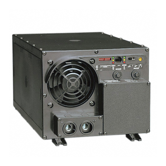
APS PowerVerter
• Voltage- and Frequency-Controlled • Peak Power • High Efficiency
Introduction
Important Safety Instructions
Configuration & Connection
Features
Maintenance and Service
Warranty
Troubleshooting
Specifications
Español
Alternative Power Sources (120V, 60 Hz)
1111 W. 35th Street Chicago, IL 60609 USA
Customer Support: (773) 869-1234 • www.tripplite.com
®
PowerVerter
is a registered trademark of Tripp Lite. All rights reserved.
1/4/02
10:37 AM
Page 1
®
2
4
5
11
14
14
15
16
18
Advertisement
Table of Contents

Related Manuals for Tripp Lite APS POWERVERTER


Summary of Contents for Tripp Lite APS POWERVERTER
-
Page 1: Important Safety Instructions
Important Safety Instructions Configuration & Connection Features Maintenance and Service Warranty Troubleshooting Specifications Español 1111 W. 35th Street Chicago, IL 60609 USA Customer Support: (773) 869-1234 • www.tripplite.com ® PowerVerter is a registered trademark of Tripp Lite. All rights reserved. -
Page 2: Introduction
200110086 120V APS MV-cabinetEn-Sp 93-2006.qxd 1/4/02 10:37 AM Page 2 Introduction Congratulations! You’ve purchased the most advanced, feature-rich integrated inverter/battery charger on the market. Your APS provides your equipment with utility-supplied AC power when it is available, and during blackouts, overvoltages and brownouts, your APS automatically switches over to an external battery source to power connected equipment with voltage and frequency-controlled AC power. - Page 3 200110086 120V APS MV-cabinetEn-Sp 93-2006.qxd 1/4/02 10:37 AM Page 3 Introduction continued 3-Stage Battery Charger Your APS recharges your battery faster than Stage 2 conventional chargers because its three-stage Absorption charger profile (Bulk, Absorption and Float) are optimized, regardless of the type of battery you use (Wet or Gel).* In addition, the advanced Stage 3 charging system protects against over-charge...
-
Page 4: Important Safety Instruction
Serious injury to property or person could result. Equipment Connection Warnings • Do not use Tripp Lite APS Systems in life support applications where a malfunction or failure of a Tripp Lite APS System could cause failure or significantly alter the perform- ance of a life support device. - Page 5 200110086 120V APS MV-cabinetEn-Sp 93-2006.qxd 1/4/02 10:37 AM Page 5 Configuration Configuration Dip Switch Settings DIP SWITCH GROUP A (All models) BATTERY TYPE / VOLTAGE POINT Using a small tool, set the 4 “Battery Type / Voltage Point” Configuration DIP Switches, Group A (located on the front panel of your APS;...
- Page 6 200110086 120V APS MV-cabinetEn-Sp 93-2006.qxd 1/4/02 10:37 AM Page 6 Configuration continued DIP SWITCH GROUP B (Available on Select Models) LOAD SHARING/EQUALIZE BATTERY CHARGE The “Load Sharing” Configuration DIP Switches, #1 and #2 of Group B (located on the front panel of your APS;...
-
Page 7: Setting Procedure
200110086 120V APS MV-cabinetEn-Sp 93-2006.qxd 1/4/02 10:38 AM Page 7 Configuration continued • Equalize Battery Charge (DIP Switch #3, Group B) This DIP Switch is momentarily engaged to begin the process of equalizing the internal resistance of your battery's cells. This can extend the useful life of certain types of batteries; consult with your battery's manufacturer to determine if your batteries could benefit from this process. -
Page 8: Battery Selection
Horizontal mounting should be used for all vehicular applications. Due to their size and weight, all APS PowerVerter systems in vehicles should be mounted on a rigid horizontal (not vertical) surface, mounting plate or bracket before battery connection. User must supply all fasteners and brackets and verify their suitability for use with the intended mounting surface. -
Page 9: Battery Connection
200110086 120V APS MV-cabinetEn-Sp 93-2006.qxd 1/4/02 10:38 AM Page 9 Battery Connection Standard 1. Connect your APS’s positive DC Terminal directly to a fuse. UL recommends that you install a recognized UL component fuse block and fuse within 18 inches of the battery. The fuse’s rating must equal or exceed the Minimum DC Fuse Rating listed in your APS model’s specifications on pages 16 or 17. - Page 10 200110086 120V APS MV-cabinetEn-Sp 93-2006.qxd 1/4/02 10:38 AM Page 10 AC Connection Before AC connection, match the power requirements of your equipment with the power output of your APS to avoid overload. When figuring the power requirements of your equipment, do not confuse “continuous” power ratings with “peak”...
-
Page 11: Features
200110086 120V APS MV-cabinetEn-Sp 93-2006.qxd 1/4/02 10:38 AM Page 11 AC Connection continued Set Operating Mode Switch • Switch to “AUTO/REMOTE” when you are using connected equipment. ADVANTAGE: Uninterruptible power supply. Provides battery backup power during blackouts or brownouts. Note: When the switch is in the “AUTO/REMOTE” position, you can operate a user-supplied switch to transfer between battery-backup and charge-only modes. -
Page 12: Indicator Lights
200110086 120V APS MV-cabinetEn-Sp 93-2006.qxd 1/4/02 10:38 AM Page 12 Switches, Indicator Lights & Other Features continued Indicator Lights 4. “LINE” (All models): This green light will turn continuously ON whenever connected equipment is receiving utility-supplied AC power and your APS is set to “AUTO/REMOTE”, meaning that it will provide battery backup if utility power fails. -
Page 13: Other Features
200110086 120V APS MV-cabinetEn-Sp 93-2006.qxd 1/4/02 10:38 AM Page 13 Switches, Indicator Lights & Other Features continued Other Features 9. DC Input Terminals (All models): The terminals’ lug screws secure the wires leading from your external battery or battery system. Your battery or battery system must provide your APS with proper DC voltage and your equipment with an adequate amp hour capacity. -
Page 14: Maintenance And Service
Limited Warranty Tripp Lite warrants its products to be free from defects in materials and workmanship for a period of one year (domestic) or 120 days (export) from the date of initial purchase. Tripp Lite’s obligation under this warranty is limited to repairing or replacing (at its sole option) any such defective products. -
Page 15: Troubleshooting
200110086 120V APS MV-cabinetEn-Sp 93-2006.qxd 1/4/02 10:38 AM Page 15 Troubleshooting Try these remedies for common APS problems before calling for help. Call Tripp Lite Customer Service at (773) 869-1234 before returning your APS for service. SYMPTOM PROBLEMS CORRECTIONS APS does not provide APS not properly connected to Connect APS to utility power. -
Page 16: Specifications
200110086 120V APS MV-cabinetEn-Sp 93-2006.qxd 1/4/02 10:38 AM Page 16 Specifications (Corded Models) CORDED MODELS: APS 1012 Weight: 26.4 lbs. INVERTER Continuous power (@ 20° C): 1000 W Surge power (5 seconds): 2000 W Efficiency (Full Load): Minimum DC Fuse Rating: 225A DC Input Current @ Nominal V DC Full Load... - Page 17 200110086 120V APS MV-cabinetEn-Sp 93-2006.qxd 1/4/02 10:38 AM Page 17 Specifications (Hardwired Models) HARDWIRED MODELS: APS 1524 APS 2012 Weight: 26.4 lbs. 38.0 lbs. INVERTER Continuous power (@ 20° C): 1500 W 2000 W Surge power (5 seconds): 3000 W 4000 W Efficiency (Full Load): Minimum DC Fuse Rating:...
-
Page 18: Manual De Operación
Configuración y Conexión Características Mantenimiento y Servicio Garantía Resolución de Problemas Especificaciones 1111 W. 35th Street Chicago, IL 60609 USA Servicios a Clientes: (773) 869-1234 • www.tripplite.com Copyright © 2001 Tripp Lite. Propiedad Literaria de Tripp Lite 2001. Reservados todos los derechos. - Page 19 200110086 120V APS MV-cabinetEn-Sp 93-2006.qxd 1/4/02 10:38 AM Page 19 Introducción Introducción ¡Felicitaciones! Usted ha adquirido el inversor / cargador de batería integrado más avanzado y con más características en el mercado. Este modelo APS suministrará a sus equipos energía de CA mientras ésta esté...
- Page 20 200110086 120V APS MV-cabinetEn-Sp 93-2006.qxd 1/4/02 10:38 AM Page 20 Introducción continua Cargador Avanzado de 3 Etapas para Baterías Este sistema APS recargará sus baterías más Stage 2 Absorption rápido que otros cargadores convencionales debido a que su perfil de recarga de 3 etapas (Alimentación Masa, Absorción...
-
Page 21: Precauciones De Operación
Precauciones Sobre la Conexión de Equipos • No utilice los Sistemas APS de Tripp Lite en aplicaciones para el soporte de la vida humana donde una falla del APS pueda causar anomalías o alterar significativamente el rendimiento del dispositivo de soporte de vida. - Page 22 200110086 120V APS MV-cabinetEn-Sp 93-2006.qxd 1/4/02 10:38 AM Page 22 Configuración Regulación de los Interruptores DIP de Configuración GRUPO A DE INTERRUPTORES DIP (Todos los modelos) TIPO DE BATERÍAS / PUNTOS DE VOLTAJA Usando una herramienta pequeña, ajuste los 4 Interruptores DIP de Configuración, Grupo A: “Battery Type / Voltage Point”...
- Page 23 200110086 120V APS MV-cabinetEn-Sp 93-2006.qxd 1/4/02 10:38 AM Page 23 Configuración continua GRUPO B DE INTERRUPTORES DIP (Modelos Selectos) COMPARTICION DE CARGA / IGUALAR CARGA DE BATERIAS Usando una herramienta pequeña, ajuste los Interruptores DIP de Configuración “Load Sharing” (compartición de carga) del Grupo B (ubicados en el panel frontal del sistema APS; vea el Diagrama 1, página 36).
- Page 24 200110086 120V APS MV-cabinetEn-Sp 93-2006.qxd 1/4/02 10:38 AM Page 24 Configuración continua • Igualar la Carga de Baterías (Interruptores DIP No. 3, Grupo B) Este interruptor DIP se acciona momentáneamente para iniciar el proceso de igualar la resistencia interna de las pilas. Con ello se prolonga la vida útil de algunos tipos de pilas; consulte con el fabricante de sus pilas para conocer si éstas se beneficiarían con dicho proceso.
- Page 25 200110086 120V APS MV-cabinetEn-Sp 93-2006.qxd 1/4/02 10:38 AM Page 25 Selección de Baterías Seleccione el Tipo de Batería(s) Seleccione una batería o sistema de baterías que suministre voltaje apropiado de CD y capacidad adecuada en amperios / hora al sistema APS.* Seleccione baterías de ciclo profundo para obtener el máximo rendimiento de su sistema APS.
- Page 26 200110086 120V APS MV-cabinetEn-Sp 93-2006.qxd 1/4/02 10:38 AM Page 26 Montaje (Opcional*) (Refiérase al diagrama 2, página 36) El usuario debe suministrar todos los sujetadores y piezas de fijación necesarias y verificar que éstas sean adecuadas para la superficie de montaje que desea utilizar. Apague el PowerVerter y todos lo equipos conectados antes de comenzar el proceso de montaje.
- Page 27 200110086 120V APS MV-cabinetEn-Sp 93-2006.qxd 1/4/02 10:38 AM Page 27 Conexión de Baterías continua Los cables de conexión de las baterías deben ser de longitud mínima posible y en ninguna circunstancia deben exceder 10 pies de longitud. Los cables cortos y de calibres espesos limitan la pérdida de voltaje de CD y permite transferencia máxima de corriente.* Debe apretar las terminales o bornes de las baterías a una torsión de aproximadamente 4 Newton-metro para crear una conexión eficiente y prevenir sobrecalentamiento excesivo.
- Page 28 200110086 120V APS MV-cabinetEn-Sp 93-2006.qxd 1/4/02 10:38 AM Page 28 Conexión de CA Antes de la conexión de CA, cerciórese de que la demanda de energía de sus equipos coincida con la capacidad de salida del APS para evitar sobrecargas. Cuando calcule la demanda de energía de sus equipos, no confunda el índice de energía “continua”...
- Page 29 200110086 120V APS MV-cabinetEn-Sp 93-2006.qxd 1/4/02 10:38 AM Page 29 Conexión de CA continua Conexión de la Salida Eléctrica de CA (Todos los modelos con cable) Simplemente conecte sus equipos a los receptáculos de CA de la unidad. Regule el Interruptor “Operating Mode” (Modo de Operación) •...
-
Page 30: Luces Indicadoras
200110086 120V APS MV-cabinetEn-Sp 93-2006.qxd 1/4/02 10:38 AM Page 30 Interruptores, Luces Indicadoras y Otras Características continua Luces Indicadoras 4. “LINE” (Línea – Todos los modelos): Esta luz verde se iluminará continuamente para indicar que los equipos conectados están recibiendo energía de CA suministrada por la compañía local de electricidad y el sistema APS está... -
Page 31: Otras Características
200110086 120V APS MV-cabinetEn-Sp 93-2006.qxd 1/4/02 10:38 AM Page 31 Interruptores, Luces Indicadoras y Otras Características continua Otras Características 9. Terminales de Entrada de CD (Todos los modelos): Las tuercas aseguran los cables provenientes de la batería externa o sistema externo de baterías. Sus baterías o sistema de baterías deben proporcionar voltaje adecuado de CD al sistema APS y a sus equipos, y también capacidad adecuada en amperios/hora. -
Page 32: Mantenimiento Y Servicio
Garantía Limitada Tripp Lite garantiza que sus productos estarán libres de defectos en materiales y mano de obra por un período de un año (unidades utilizadas en EE.UU.) ó 120 días (unidades utilizadas fuera de EE.UU) a partir de la fecha inicial de compra. -
Page 33: Resolucion De Problemas
10:38 AM Page 33 Resolucion de Problemas Si experimenta problemas comunes refiérase a esta guía antes de llamar al centro de servicios. Llame al Servicios a Clientes de Tripp Lite antes de enviar el sistema APS. SIMTOMA PROBLEMAS SOLUCION El sistema APS no suministra... -
Page 34: Especificaciones
200110086 120V APS MV-cabinetEn-Sp 93-2006.qxd 1/4/02 10:38 AM Page 34 Especificaciones (Modelos con cable) MODELOS CON CABLE: APS1012 Peso: 11.9 Kg 11.9 Kg INVERSOR Energía continua a 20º C 1000 Vatios Energía de sobretensiones transitorias (5 segundos): 2000 Vatios Eficiencia (Carga Completa): Indice Mínimo de Capacidad del Fusible: 225A Corriente de Entrada de CD a Niveles Nominales... - Page 35 200110086 120V APS MV-cabinetEn-Sp 93-2006.qxd 1/4/02 10:38 AM Page 35 Especificaciones (Modelos con toma directa al circuito) MODELOS CON TOMA DIRECTA AL CIRCUITO: APS1524 APS2012 Peso: 12.0 Kg 17.1 Kg INVERSOR Energía continua a 20º C 1500 Vatios 2000 Vatios Energía de sobretensiones transitorias (5 segundos): 3000 Vatios 4000 Vatios...
- Page 36 200110086 120V APS MV-cabinetEn-Sp 93-2006.qxd 1/4/02 10:38 AM Page 36 Diagrams/Esquemas See “Configuration”, pg. 5. 1.1 is DIP Switch Group A. 1.2 is DIP Switch Group B. Refiérase a la sección “Configuración”, página 22. 1.1 representa el Grupo A de Interruptores DIP. 1.2 representa el Grupo B de Interruptores DIP OUTPUT/NEUTRA OUTPUT/HOT...
- Page 37 200110086 120V APS MV-cabinetEn-Sp 93-2006.qxd 1/4/02 10:38 AM Page 37 Diagrams/Esquemas X Volts See Battery Connection, Pg. 9. 4.1 is the fuse. X = Your APS’s Inverter's Nominal Input Voltage. (See specs.) Refiérase a la sección “Conexión de Baterías”, página 26. 4.1 representa el fusible. X = El Voltaje Nominal de Entrada del Inversor del APS.
- Page 38 200110086 120V APS MV-cabinetEn-Sp 93-2006.qxd 1/4/02 10:38 AM Page 38 Diagrams/Esquemas Basic 12VDC Vehicular Battery Connection. See Pg. 9. 7.1 is the alternator. 7.2 is the vehicle battery ground. 7.3 is the vehicle battery. 7.4 is the fuse. Conexión Básica de Baterías de 12V de CD en Vehículos. Vea página 27. 7.1 representa el alternador.
- Page 39 200110086 120V APS MV-cabinetEn-Sp 93-2006.qxd 1/4/02 10:38 AM Page 39 Diagrams/Esquemas Corded Model • Modelo con Cable 1. Operating Mode Switch (All models) 1. Interruptor “Operating Mode” (Modo de operación) 2. DIP Switch Group A (All models) 2. Grupo A de Interruptores DIP 3.
- Page 40 200110086 120V APS MV-cabinetEn-Sp 93-2006.qxd 1/4/02 10:38 AM Page 40 Diagrams/Esquemas Hardwired Model • Modelo con Toma Directa al Circuito OUTPUT/NEUTRA OUTPUT/HOT GROUND INPUT/NEUTRA INPUT/HOT “FOR USE WITH COPPER WIRE ONLY” 1. Operating Mode Switch (All models) 1. Interruptor “Operating Mode” (Modo de operación) (Todos los modelos) 2.