Table of Contents
Advertisement
Quick Links
Owner's Manual
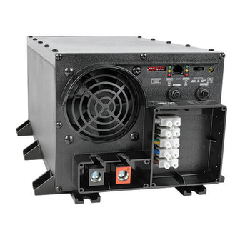
APS PowerVerter
• Voltage- and Frequency-Controlled • Peak Power • High Efficiency
Introduction
Important Safety Instructions
Configuration & Connection
Features
Maintenance and Service
Limited Warranty
Troubleshooting
Specifications
Español
Alternative Power Sources (230V, 50 Hz)
1111 W. 35th Street Chicago, IL 60609 USA
Customer Support: (773) 869-1234 • www.tripplite.com
®
PowerVerter
is a registered trademark of Tripp Lite. All rights reserved.
®
2
4
5
11
14
14
15
16
18
Advertisement
Table of Contents

Related Manuals for Tripp Lite 93-2007 (200106010)


Summary of Contents for Tripp Lite 93-2007 (200106010)
- Page 1 Important Safety Instructions Configuration & Connection Features Maintenance and Service Limited Warranty Troubleshooting Specifications Español 1111 W. 35th Street Chicago, IL 60609 USA Customer Support: (773) 869-1234 • www.tripplite.com PowerVerter ® is a registered trademark of Tripp Lite. All rights reserved. ®...
-
Page 2: Introduction
Introduction Congratulations! You’ve purchased the most advanced, feature-rich integrated inverter and battery charger on the market. Your APS provides your equipment with utility-supplied AC power when it is available, and during blackouts, overvoltages and brownouts, your APS automatically switches over to an external battery source to power connected equipment with voltage and frequency-controlled AC power. - Page 3 Introduction 3-Stage Battery Charger Your APS recharges your battery faster than conventional chargers because its three-stage charger profile (Bulk, Absorption and Float) are optimized, regardless of the type of battery you use (Wet or Gel).* In addition, the advanced charging system protects against over-charge and over-dis- charge to ensure a longer service life from your bat- tery.
-
Page 4: Important Safety Instructions
Serious injury to property or person could result. Equipment Connection Warnings • Do not use Tripp Lite APS Systems in life support applications where a malfunction or failure of a Tripp Lite APS System could cause failure or significantly alter the performance of a life support device. - Page 5 Configuration Configuration Dip Switch Settings DIP SWITCH GROUP A BATTERY TYPE / VOLTAGE POINT Using a small tool, set the 4 “Battery Type / Voltage Point” Configuration DIP Switches, Group A (located on the front panel of your APS; see Diagram 1, p. 36) to select battery type and set the voltage range outside of which your APS will switch to battery power.
- Page 6 Configuration DIP SWITCH GROUP B LOAD SHARING/EQUALIZE BATTERY CHARGE Using a small tool, set the “Load Sharing” Configuration DIP Switches, #1 and #2 of Group B (located on the front panel of your APS; see Diagram 1, p. 36). DIP Switch #3, Group B should be kept in the “UP”...
-
Page 7: Setting Procedure
Configuration • Equalize Battery Charge This DIP Switch is momentarily engaged to begin the process of equalizing the internal resistance of your battery’s cells. This can extend the useful life of certain types of batteries; consult with your battery's manufacturer to determine if your batteries could benefit from this process. The charge equalization process is automatic and once started can only be stopped by removing the input power. -
Page 8: Battery Selection
Battery Selection Selecting Battery Type Select a battery or system of batteries that will provide your APS with proper DC voltage and an adequate amp hour capacity.* Select ‘Deep-Cycle’ batteries to enjoy optimum performance from your APS. Batteries of either Wet-Cell (vented) or Gel-Cell/Absorbed Glass Mat (sealed) construction are ideal. -
Page 9: Battery Connection
Connect your APS’s positive DC Terminal directly to a fuse. Tripp Lite recommends that you install a recognized component fuse block and fuse within 18 inches of the battery. The fuse's rating must equal or exceed the Minimum DC Fuse Rating listed in your APS model’s specifications on pages 16 or 17. - Page 10 (A technician may be able to convert your APS to receive 60 Hz. power. Consult Tripp Lite for details.) Make sure that the circuit you connect your APS to has adequate overload protection, such as a circuit breaker or a fuse.
-
Page 11: Features
AC Connection AC Output Electrical Connection Simply plug your equipment into the unit’s AC receptacles. If adapters must be used, choose adapters that provide a connection to ground. Set Operating Mode Switch • Switch to “AUTO/REMOTE” when you are using connected equipment. ADVANTAGE: Uninterruptible power supply. -
Page 12: Indicator Lights
Switches, Indicator Lights & Other Features Indicator Lights 4. “LINE” (All models): This green light will turn continuously ON whenever connected equipment is receiving utility-supplied AC power and your APS is set to “AUTO/REMOTE”, meaning that it will provide battery backup if utility power fails. It will flash intermittently when connected equipment is receiving utility power and your APS’s Operating Mode Switch is set to “CHARGE ONLY”... -
Page 13: Other Features
Switches, Indicator Lights & Other Features Other Features 9. DC Input Terminals (All models): The terminals’ lug screws secure the wires leading from your external battery or battery system. Your battery or battery system must provide your APS with proper DC voltage and your equipment with an adequate amp hour capacity. See Battery Selection section, pg. -
Page 14: Maintenance And Service
Limited Warranty Tripp Lite warrants its products to be free from defects in materials and workmanship for a period of one year (domestic) or 120 days (export) from the date of initial purchase. Tripp Lite’s obligation under this warranty is limited to repairing or replacing (at its sole option) any such defective products. -
Page 15: Troubleshooting
Troubleshooting Try these remedies for common APS problems before calling for help. Call Tripp Lite Customer Service at (773) 869-1234 before returning your APS for service. SYMPTOM APS does not provide AC output (AC input present) APS does not provide... -
Page 16: Specifications
Automatic Transfer Time: * Load sense can reduce this to 1/30 of the listed current. **Factory default setting. † A technician may be able to convert your UPS to receive 60 Hz ±10%power. Consult Tripp Lite for details. (Corded Models) APSINT1012 11.9 Kg... - Page 17 *Load sense can reduce this to 1/30 of the listed current. **Factory default setting. ***When AVR is boosting incoming current.†A technician may be able to convert your UPS to receive 60 Hz ±10%power. Consult Tripp Lite for details. (Hardwired Models) APSINT1524 12.7 Kg...
- Page 18 Diagrams/Esquemas See “Configuration”, pg. 5. 1.1 is DIP Switch Group A. 1.2 is DIP Switch Group B. Refiérase a la sección “Configuración”, página 22. 1.1 representa el Grupo A de Interruptores DIP. 1.2 representa el Grupo B de Interruptores DIP See Hardwire Electrical Connections, pg.
- Page 19 Diagrams/Esquemas See Battery Connection, Pg. 9. 4.1 is the fuse. X = Your APS’s Inverter's Nominal Input Voltage. (See specs.) Refiérase a la sección “Conexión de Baterías”, página 26. 4.1 representa el fusible. X = El Voltaje Nominal de Entrada del Inversor del APS.
- Page 20 Diagrams/Esquemas Basic 12VDC Vehicular Battery Connection. See Pg. 9. 7.1 is the alternator. 7.2 is the vehicle battery ground. 7.3 is the vehicle battery. 7.4 is the fuse. Conexión Básica de Baterías de 12V de CD en Vehículos. Vea página 27. 7.1 representa el alternador.
- Page 21 Diagrams/Esquemas Corded Model • Modelo con Cable 1. Operating Mode Switch (All models) 2. DIP Switch Group A (All models) 3. DIP Switch Group B (Select models only) 4. “LINE” (All models) 5. “INV” (Inverting—all models) 6. “LOAD” (All models) 8.
- Page 22 Diagrams/Esquemas Hardwired Model • Modelo con Toma Directa al Circuito 1. Operating Mode Switch (All models) 2. DIP Switch Group A (All models) 3. DIP Switch Group B (Select models only) 4. “LINE” (All models) 5. “INV” (Inverting—all models) 6. “LOAD” (All models) 7.