Tripp Lite B092-016 Owner's Manual
Console server management switch console server with poweralert console server
Hide thumbs
Also See for B092-016:
- Owner's manual (242 pages) ,
- Quick start manual (4 pages) ,
- Specification sheet (3 pages)
Table of Contents
Advertisement
Owner's Manual
Console Server Management Switch
Models:
B096-016 / B096-048
Console Server with PowerAlert
Model:
B092-016
Console Server
Models:
B095-004-1E / B095-003-1E-M / B094-008-2E-M-F
Tripp Lite World Headquarters
1111 W. 35th Street, Chicago, IL 60609 USA
www.tripplite.com/support
Copyright © 2012 Tripp Lite. All rights reserved. All trademarks are the property of their respective owners.
1
Advertisement
Table of Contents

Related Manuals for Tripp Lite B092-016


Summary of Contents for Tripp Lite B092-016
- Page 1 Model: B092-016 Console Server Models: B095-004-1E / B095-003-1E-M / B094-008-2E-M-F Tripp Lite World Headquarters 1111 W. 35th Street, Chicago, IL 60609 USA www.tripplite.com/support Copyright © 2012 Tripp Lite. All rights reserved. All trademarks are the property of their respective owners.
- Page 2 The user must use shielded cables and connectors with this equipment. Any changes or modifications to this equipment not expressly approved by Tripp Lite could void the user’s authority to operate this equipment.
-
Page 3: Table Of Contents
Power: Console Server Management Switch 2.2.2 Power: Console Server with PowerAlert 2.2.3 Power: Console Server Network Connection Serial Port Connection USB Port Connection Rackmount Console / KVM Connection (B092-016 only) System Configuration Management Console Connection 3.1.1 Connected computer set up 3.1.2 Browser connection 3.1.3... - Page 4 Table of Contents Serial Port, Host, Device & User Configuration Configuring Serial Ports 4.1.1 Common Settings 4.1.2 Console Server Mode 4.1.3 SDT Mode 4.1.4 Device (RPC, UPS, EMD) Mode 4.1.5 Terminal Server Mode 4.1.6 Serial Bridging Mode 4.1.8 Syslog Add/ Edit Users Authentication Network Hosts Trusted Networks Serial Port Cascading 4.6.1 Automatically generate and upload SSH keys 4.6.2 Manually generate and upload SSH keys 4.6.3...
- Page 5 Table of Contents SSH Tunnels & SDT Connector Configuring for SDT Tunneling to Hosts SDT Connector Configuration 6.2.1 SDT Connector client installation 6.2.2 Configuring a new gateway in the SDT Connector client 6.2.3 Auto-configure SDT Connector client with the user’s access privileges 6.2.4 Make an SDT connection through the gateway to a host 6.2.5 Manually adding hosts to the SDT Connector gateway 6.2.6 Manually adding new services to the new hosts 6.2.7 Adding a client program to be started for the new service 6.2.8 Dial-in configuration SDT Connector to Management Console...
- Page 6 Table of Contents Remote Log Storage Serial Port Logging Network TCP or UDP Port Logging Auto-Response Event logging Power Device Logging Power and Environmental Monitoring Remote Power Control (RPC) 8.1.1 RPC connection 8.1.2 RPC alerts 8.1.3 RPC status 8.1.4 User power management Uninterruptible Power Supply Control (UPS) 8.2.1 Managed UPS connections 8.2.2...
- Page 7 12.5 Dashboard 12.5.1 Configuring the Dashboard 12.5.2 Creating custom widgets for the Dashboard Management 13.1 Device Management 13.2 Port and Host Log Management 13.3 Terminal Connection 13.3.1 Web Terminal 13.3.1.1 Web Terminal to Command Line 13.3.1.2 Web Terminal to Serial Device 13.3.2 SDTConnector access 13.4 Power Management 13.5 Remote Console Access (B092-016 only)
- Page 8 Table of Contents Configuration from the Command Line 14.1 Accessing config from the command line 14.1.1 Serial Port configuration 14.1.2 Adding and removing Users 14.1.3 Adding and removing user Groups 14.1.4 Authentication 14.1.5 Network Hosts 14.1.6 Trusted Networks 14.1.7 Cascaded Ports 14.1.8 UPS Connections 14.1.9 RPC Connections 14.1.10 Environmental 14.1.11 Managed Devices 14.1.12 Port Log 14.1.13 Alerts 14.1.14 SMTP & SMS 14.1.15 SNMP 14.1.16 Administration...
- Page 9 15.9.2 pmpower 15.9.3 Adding new RPC devices 15.10 IPMItool 15.11 Scripts for Managing Slaves 15.12 SMS Server Tools 15.13 Multicast Thin Client (B092-016) 16.1 Local Client Service Connections 16.1.1 Connect: Serial Terminal 16.1.2 Connect: Browser 16.1.3 Connect: VNC 16.1.4 Connect: SSH 16.1.5 Connect: IPMI 16.1.6...
-
Page 10: Introduction
Chapter 1: Introduction This User Manual is provided to help you get the most from your B096-016 / B096-048 Console Server Management Switch, B092-016 Console Server with PowerAlert or B095-004-1E / B095-003-1E-M / B094-008-2E-M-F Console Server product. These products are referred to generically in this manual as Console Servers. Once configured, you will be able to use your Console Server to securely monitor, access and control the computers, networking devices, telecommunications equipment, power supplies and operating environment in your data center, branch office or communications room. This manual guides you in managing this infrastructure locally (at the rack side or across your operations or management LAN or through the local serial console port), and remotely (across the Internet, private network or via dial up). Manual Organization This manual contains the following chapters: 1. Introduction An overview of the features of the Console Server and information on this manual 2. Installation... -
Page 11: Types Of Users
Management Console to access configured devices and review port logs. In this manual, when the term user (lower case) is used, it is referring to both the above classes of users. This document also uses the term remote users to describe users who are not on the same LAN segment as the Console Server. These remote users may be Users, who are on the road connecting to managed devices over the public Internet, or it may be an Administrator in another office connecting to the Console Server itself over the enterprise VPN, or the remote user may be in the same room or the same office but connected on a separate VLAN to the Console Server. Management Console The Console Server Management Console runs in a browser. It provides a view of your Console Server Management Switch (B096-016/048), Console Server with PowerAlert (B092-016) or Console Server (B095-004/003 and B094-008-2E-M-F) product and all the connected equipment. Administrators can use the Management Console, either locally or from a remote location, to configure the Console Server, set up Users, configure the ports and connected hosts, and set up logging and alerts. An authorized User can use the Management Console to access and control configured devices, review port logs, use the in-built Web terminal to access serially attached consoles and control power to connected devices. - Page 12 SSH or Telnet connecting to the Console Server over the LAN; or by connecting to the Console Server through an SSH tunnel using the SDTConnector. The B092-016 Console Server also has PowerAlert software and a selection of thin clients embedded (RDP , Firefox etc). You will be able to use these consoles as well as the standard Management Console for access and control.
- Page 13 Chapter 1: Introduction Publishing history Date Revision Update details January 2009 Initial draft February 2009 0.91 Pre-release January 2010 1.01 Add B095-004/003 Console Server and Firmware 3.0.1 features January 2011 Firmware 3.3.2 features March 2011 2.0.1 Support for additional USB ports and 16GB internal flash in B096-016 / B096-048 February 2012 2.0.02 Add B094-008-2E-M-F and 3.5.2 firmware features...
-
Page 14: Installation
Console Server Model Serial Ports Network Ports Console Port USB Port Modem Power B096-048 Internal Dual AC Universal Input B096-016 Internal Dual AC Universal Input B092-016 1+KVM Single AC Universal Input B095-004-1E External DC Supply B095-003-1E-M Internal External DC Supply B094-008-2E-M-F Internal External DC Supply 2.1.1 Kit components: B096-048 and B096-016 Console Server Management Switch... -
Page 15: Kit Components: B092-016 Console Server With Poweralert
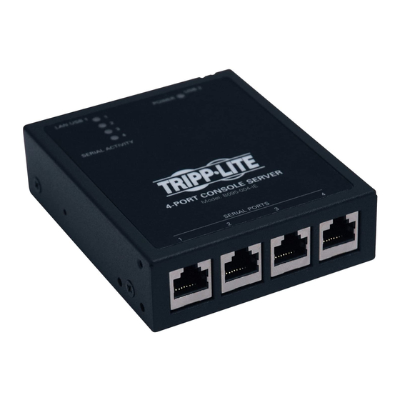
Chapter 2: Installation 2.1.2 Kit components: B092-016 Console Server with PowerAlert B092-016 Console Server with PowerAlert 2 x Cable UTP Cat5 blue Connector DB9F-RJ45S straight and DB9F-RJ45S cross-over AC power cable Quick Start Guide and CD-ROM • Unpack your Console Server and verify you have all the parts shown above, and that they all appear in good working order • If you are installing your Console Server in a rack, you will need to attach the rack mounting brackets supplied with the unit, and install the unit in the rack. Take care to heed the Safety Precautions listed earlier • Proceed to connect your B092-016 to the network, to the serial and USB ports of the controlled devices, to any rack side LCD console or KVM switch, and to power as outlined below 2.1.3 Kit components: B095-004-1E and B095-003-1E-M Console Server B095-004-1E 4-port Console Server with single NIC or B095-003-1E-M 3- port Console... -
Page 16: Kit Components: B094-008-2E-M-F Console Server
Chapter 2: Installation 2.1.4 Kit components: B094-008-2E-M-F Console Server B094-008-2E-M-F 8- port Console Server with dual NIC and modem 2 x Cable UTP Cat5 blue Connectors DB9F-RJ45S straight and cross-over External power supply Quick Start Guide and CD-ROM • Unpack your Console Server kit and verify you have all the parts shown above, and they all appear to be in good working order • If you are installing your Console Server in a rack, you will need to attach the rack mounting brackets supplied with the unit and install the unit in the rack. Follow the Safety Precautions • Proceed to connect your Console Server to the network, to the serial ports of the controlled devices, and to power as outlined below... -
Page 17: Power Connection
Tripp Lite. 2.2.2 Power: Console Server with PowerAlert The standard B092-016 Console Server has a built-in universal auto-switching AC power supply. This power supply accepts AC input voltage between 100 and 240 VAC with a frequency of 50 or 60 Hz and the power consumption is less than 40W. The AC power socket is located at the rear of the B092-016. This power inlet uses a conventional AC power cord. A North American power cord is provided by default. Power cords for other regions are available separately from Tripp Lite. 2.2.3 Power: Console Server The B095-004/003 and B094-008-2E-M-F Console Servers each have an external wall-mount power supply. This power supply accepts AC input voltage between 100 and 240 VAC with a frequency of 50 or 60 Hz and the total power consumption per console server is less than 20W. The DC power socket on the Console Server is located on the side of the metal case marked PWR. -
Page 18: Serial Port Connection
USB ports. Note: The B094-008-2E-M-F Console Server ships with an internal 4GB USB memory which can be used for extended log file storage There are four USB 2.0 ports on the rear panel of the B092-016 Console Server and one USB2.0 port located under the RJ45 10/100 LAN connector on the B095-004/003 Console Server. These ports are used to connect to USB consoles (of managed UPS hardware) and to other external devices (such as a USB memory stick or keyboard). External USB devices (including USB hubs) can be plugged into any Console Server USB port. Rackmount Console / KVM Connection (B092-016 only) B092-016 Console Server with PowerAlert can be connected directly to a rackmount console (such as B021-000-17 or B021-019 by Tripp Lite) to provide direct local management right at the rack. Connect the rackmount console’s PS/2 Keyboard/Mouse and VGA connectors directly to the PS/2 and VGA connectors on the B092-016. The default video resolution is 1024 x 768. The B092-016 Console Server also supports the use of a USB keyboard/mouse. Alternately, the B092-016 Console Server can also be connected locally to a KVM (or KVMoIP) switch at the rack. The B092- 016 Console Server with PowerAlert will enable you then to use this KVM infrastructure to run PowerAlert, to manage your power devices and to run the thin clients to manage other devices. -
Page 19: System Configuration
Chapter 3: Initial System Configuration This chapter provides step-by-step instructions for the initial configuration of your Console Server and connecting it to your management or operational network. This involves the Administrator: • Activating the Management Console • Changing the Administrator password • Setting the IP address for the Console Server’s principal LAN port • Selecting the network services to be supported This chapter also discusses the communications software tools that the Administrator may use to access the Console Server. It also covers the configuration of the additional LAN ports on the B096-016/048 Console Server Management Switch. -
Page 20: Browser Connection
Chapter 3: Initial System Configuration Now add a static entry to the ARP table and ping the Console Server to assign the IP address to the console server. In the example below, a Console Server has a MAC Address 00:13:C6:00:02:0F (designated on the label on the bottom of the unit) and we are setting its IP address to 192.168.100.23. Also the PC/workstation issuing the arp command must be on the same network segment as the Console Server (that is, have an IP address of 192.168.100.xxx) • Type arp -s 192.168.100.23 00-13-C6-00-02-0F (Note for UNIX the syntax is: arp -s 192.168.100.23 00:13:C6:00:02:0F). • Type ping -t 192.18.100.23 to start a continuous ping to the new IP Address. • Turn on the Console Server and wait for it to configure itself with the new IP address. It will start replying to the ping at this point. • Type arp –d to flush the ARP cache again. -
Page 21: Initial B092-016 Connection
Note: If you are not able to connect to the Management Console at 192.168.0.1 or if the default Username / Password were not accepted then reset your Console Server (refer Chapter 10) 3.1.3 Initial B092-016 connection You can configure the B092-016 Console Server using a connected computer and browser connection as described in the two sections above, or you can configure it directly. To do this you will need to connect a console (keyboard, mouse and display) or a KVM switch directly to its mouse, keyboard and VGA ports. When you initially power on the B092-016, you will be prompted on your directly connected video console to log in • Enter the default administration username and password (Username: root Password: default). The B092-016 control panel will be displayed • Click the Configure button on the control panel. This will load the Firefox browser and open the B092-016 Management Console • At the Management Console menu select System: Administration... -
Page 22: Administrator Password
Chapter 3: Initial System Configuration Administrator Password For security reasons, only the administration user named root can initially log into your Console Server. Only those people who know the root password can access and reconfigure the Console Server itself. However, anyone who correctly guesses the root password (and the default root password which is default) could gain access. It is therefore essential that you enter and confirm a new root password before giving the Console Server any access to, or control of, your computers and network appliances. • Select System: Administration • Enter a new System Password then re-enter it in Confirm System Password. This is the new password for root, the main administrative user account, so it is important that you choose a complex password, and keep it safe • You may now wish to enter a System Name and System Description for the Console Server to give it a unique ID and make it simple to identify Note: The System Name can contain from 1 to 64 alphanumeric characters (however you can also use the special characters "-"... -
Page 23: Network Ip Address
Chapter 3: Initial System Configuration Network IP Address It is time to enter an IP address for the principal 10/100 LAN port on the Console Server; or enable its DHCP client so that it automatically obtains an IP address from a DHCP server on the network to which it is to be connected. • On the System: IP menu select the Network Interface page then check DHCP or Static for the Configuration Method • If you select Static you must manually enter the new IP Address, Subnet Mask, Gateway and DNS server details. This selection automatically disables the DHCP client • If you selected DHCP the Console Server will look for configuration details from a DHCP server on your management LAN. -
Page 24: Ipv6 Configuration
Chapter 3: Initial System Configuration 3.3.1 IPv6 configuration By default, the Console Server Ethernet interfaces support IPv. However, they can also be configured for IPv6 operation: • On the System: IP menu select General Settings page and check Enable IPv6 • You will then need to configure the IPv6 parameters on each network interface page... -
Page 25: Dynamic Dns (Ddns) Configuration
Chapter 3: Initial System Configuration 3.3.2 Dynamic DNS (DDNS) configuration Dynamic DNS (DDNS) enables a Console Server with a dynamically assigned IP address (that may change from time to time) to be located using a fixed host or domain name. • The first step in enabling DDNS is to create an account with the supported DDNS service provider of your choice. Supported DDNS providers include: DyNS www.dyns.cx dyndns.org www.dyndns.org GNUDip gnudip.cheapnet.net ODS www.ods.org TZO www.tzo.com 3322.org (Chinese provider) www.3322.org Upon registering with the DDNS service provider, you will select a username and password, as well as a hostname that you will use as the DNS name (to allow external access to your machine using a URL). The Dynamic DNS service providers allow the user to choose a hostname URL and set an initial IP address to correspond to that hostname URL. Many Dynamic DNS providers offer a selection of URL hostnames available for free use with their service. However, with a paid plan, any URL hostname (including your own registered domain name) can... -
Page 26: System Service Access
Chapter 3: Initial System Configuration System Service Access Service Access specifies which access protocols/services can be used to access the Console Server (and connected serial ports). The Administrator can access and configure the Console Server (and connected devices) using a range of access protocols/ services – and for each such access, the particular service must be running with access through the firewall enabled. By default HTTP , HTTPS, Telnet and SSH services are running, and these services are enabled on all network interfaces. However, again by default, only HTTPS and SSH access to the Console Server is enabled, while HTTP and Telnet access is disabled. For other services, such as SNMP/Nagios NRPE/NUT, the service must first be started on the relevant network interface using Port Rules (refer Chapter 5.7). Then the Services Access can be set to allow or block access. To change the access settings: • Select the Service Access tab on the System: Firewall page. This will displays the services currently enabled for the Console Server’s network interfaces. Depending on the particular Console Server model the interfaces displayed may include : o Network interface (for the principal Ethernet connection) o Dial out (V90 and cellular modem) - Page 27 Chapter 3: Initial System Configuration The Services Access settings specify which services the Administrator can use over which network interface to access the console server. It also nominates the enabled services that the Administrator and the User can use to connect through the Console Server to attached serial and network connected devices. • The following general service access options can be specified: HTTPS This ensures the Administrator has secure browser access to all the Management Console menus on the Console Server. It also allows appropriately configured Users secure browser access to selected Manage menus.
- Page 28 Chapter 3: Initial System Configuration • The B092-016 Console Server with PowerAlert also presents some additional service and configuration options: The B092-016 Console Server has an internal VNC server. When enabled, it allows remote users to connect to the Console Server and run the PowerAlert software and any other embedded thin client programs as if they were plugged in locally to the KVM connectors on the B092-016 (refer to Chapter 16 for more details). Users connect using port 5900 and need to run a VNC client applet Secure This enables a secure encrypted remote connection using VNC over SSL on port 5800 to the B092-016 Console Server (refer to Chapter 16) PowerAlert This configuration option will automatically start the PowerAlert application on the B092-016 and display the console as soon as you log into the local display or VNC session (refer to Chapter 16). The complete PowerAlert manual can be downloaded at www.tripplite.com/EN/support/PowerAlert/Downloads.cfm...
-
Page 29: Communications Software
Chapter 3: Initial System Configuration Communications Software You need to configure the access protocols that the communications software on the Administrator and User Computer will use when connecting to the Console Server (and when connecting to serial devices and network hosts which are attached to the Console Server). This section provides an overview of the communications software tools that can be used on the remote computer. Tripp Lite recommends the SDT Connector software tool that is provided with the Console Server; however, generic tools such as PuTTY and SSHTerm may also be used. 3.5.1 SDT Connector We recommend using the SDT Connector communications software for all communications with Console Servers. -
Page 30: Sshterm
Chapter 3: Initial System Confi guration 3.5.3 SSHTerm Another common communications package that may be useful is SSHTerm. This is an open source package that can be downloaded from http://sourceforge.net/projects/sshtools • To use SSHTerm for an SSH terminal session from a Windows Client, simply Select the ‘File’ option and click on ‘New Connection’. • A new dialog box will appear for your ‘Connection Profi le’. Type in the host name or IP address (for the Console Server unit) and the TCP port that the SSH session will use (port 22). Then type in your username and choose password authentication and click Connect. • A message may appear about the host key fi ngerprint. You will need to select ‘Yes’ or ‘Always’ to continue. -
Page 31: Management Network Configuration
Chapter 3: Initial System Configuration Management Network Configuration The B096-048/016 Console Server Management Switches and B094-008-2E-M-F Console Server each have an additional network port that can be configured as a Management LAN port or as a failover/ OOB access port. 3.6.1 Enable the Management LAN The B096-048/016 Console Server Management Switches and B094-008-2E-M-F Console Server have dual Ethernet ports which can be configured to provide a management LAN gateway. With this configuration, the B096-048/016 and B094-008- 2E-M-F provide firewall, router and DHCP server features and you can connect managed hosts to this management LAN. These features are all disabled by default. To configure the Management LAN gateway: • Select the Management LAN Interface page on the System: IP menu and uncheck Disable • Configure the IP Address and Subnet Mask for the Management LAN (but leave the DNS fields blank) • Click Apply Note: With the B094-008-2E-M-F, B096-048 and B096-016 the second Ethernet port can be configured as either a gateway port or it can be configured as an OOB/Failover port - but not both. -
Page 32: Configure The Dhcp Server
Chapter 3: Initial System Configuration 3.6.2 Configure the DHCP server The Console Servers also host a DHCP server which by default is disabled. The DHCP server enables the automatic distribution of IP addresses to devices on the Network Interface or the Management LAN. To enable the DHCP server: • On the System: IP menu select the Management LAN Interface page and click the Disabled label in the DHCP Server field (or go to the System: DHCP Server menu and check Enable DHCP Server) • Enter the Gateway address that is to be issued to the DHCP clients. If this field is left blank, the Console Server’s IP address will be used • Enter the Primary DNS and Secondary DNS address to issue the DHCP clients. Again if this field is left blank, Console... -
Page 33: Select Failover Or Broadband Oob
Chapter 3: Initial System Configuration The DHCP server also supports pre-assigning IP addresses to be allocated only to specific MAC addresses and reserving IP addresses to be used by connected hosts with fixed IP addresses. To reserve an IP addresses for a particular host: • Click Add in the Reserved Addresses field • Enter the Hostname, the Hardware Address (MAC) and the Statically Reserved IP address for the DHCP client and click Apply When DHCP has initially allocated hosts addresses it is recommended to copy these into the pre-assigned list so the same IP address will be reallocated in the event of a reboot. -
Page 34: Bridging The Network Ports
Chapter 3: Initial System Configuration 3.6.4 Bridging the network ports By default the B096-048/016 Console Server's Management LAN network port can only be accessed using SSH tunneling / port forwarding or by establishing an IPsec VPN tunnel to the Console Server. However the network ports on the Console Servers can be bridged. • Select Enable Bridging on the System: IP General Settings menu With bridging enabled: • the Ethernet ports are transparently interconnected at the data link layer (layer 2) • the Ethernet ports are configured collectively using the Network Interface menu • network traffic is forwarded between all Ethernet ports with no firewall restrictions • the Management LAN Interface and Out-of-Band/Failover Interface functions are removed and the DHCP Server is disabled... -
Page 35: Static Routes
Chapter 3: Initial System Configuration The Console Server enables access and control of serially-attached devices and network-attached devices (hosts). The Administrator must configure access privileges for each of these devices, and specify the services that can be used to control the devices. The Administrator can also set up new users and specify each user’s individual access and control privileges. This chapter covers each of the steps in configuring hosts and serially attached devices: • Configure Serial Ports – setting up the protocols to be used in accessing serially-connected devices • Users & Groups – setting up users and defining the access permissions for each of these users • Authentication –... -
Page 36: Serial Port, Host, Device & User Configuration
Chapter 4: Serial Port, Device and User Configuration Configuring Serial Ports To configure a serial port you must first set the Common Settings (Chapter 4.1.1) that are to be used for the data connection to that port (e.g. baud rate) and the mode the port is to operate in. Each port can be set to support one of five operating modes: Console Server Mode (Chapter 4.1.2) is the default setting and enables general access to the serial console port on serially attached devices Device Mode (Chapter 4.1.3) sets the serial port up to communicate with an intelligent serial controlled PDU, UPS or Environmental Monitor Devices (EMD) iii. SDT Mode (Chapter 4.1.4) enables graphical console access (with RDP , VNC, HTTPS etc) to hosts that are serially connected iv. -
Page 37: Common Settings
Chapter 4: Serial Port, Device and User Configuration 4.1.1 Common Settings There are a number of common settings available for each serial port. These are independent of the mode in which the port is being used. These serial port parameters must be set so they match the serial port parameters on the device which is attached to that port. -
Page 38: Console Server Mode
Chapter 4: Serial Port, Device and User Configuration 4.1.2 Console Server Mode Select Console Server Mode to enable remote management access to the serial console that is attached to the serial port: Logging Level This specifies the level of information to be logged and monitored (refer to Chapter 7 - Alerts and Logging) Telnet Check to enable Telnet access to the serial port. When enabled, a Telnet client on a User or Administrator’s computer can connect to a serial device attached to this serial port on the Console Server. - Page 39 Chapter 4: Serial Port, Device and User Configuration Note: In Console Server mode, Users and Administrators can use SDT Connector to set up secure Telnet connections that are SSH tunneled from their client computers to the serial port on the Console Server with a simple point-and-click. To use SDT Connector to access consoles on the Console Server serial ports, configure the SDT Connector with the Console Server as a gateway, then as a host.
- Page 40 Chapter 4: Serial Port, Device and User Configuration SSH It is recommended that the User or Administrator uses SSH as the protocol for connecting to serial consoles attached to the Console Server when communicating over the Internet or any other public network. This will provide an authenticated, encrypted connection between the SSH client program on the remote user’s computer and the Console Server. The user’s communication with the serial device attached to the Console Server is therefore secure. It is recommended for Users and Administrators to use SDT Connector when making an SSH connection to the consoles on devices attached to the Console Server’s serial ports. Configure the SDT Connector with the Console Server as a gateway, then as a host, and enable SSH service on Port (3000 + serial port #) i.e. 3001-3048 (refer to Chapter 6). You can also use common communications packages, like PuTTY or SSHTerm to SSH connect directly to port address IP Address _ Port (3000 + serial port #) i.e. 3001–3048.
-
Page 41: Sdt Mode
Chapter 4: Serial Port, Device and User Configuration Unauthenticated Telnet Selecting Unauthenticated Telnet enables Telnet access to the serial port without requiring the user to provide credentials. When a user accesses the Console Server to Telnet to a serial port they are normally given a login prompt. However, with unauthenticated Telnet, they connect directly through to port with any Console Server login at all. -
Page 42: Device (Rpc, Ups, Emd) Mode
4.1.4 Device (RPC, UPS, EMD) Mode This mode configures the selected serial port to communicate with a serial controlled Uninterruptible Power Supply (UPS), serial Remote Power Controller/ Power Distribution Unit (RPC) or Environmental Monitoring Device (EMD) • Select the desired Device Type (UPS, RPC or EMD) • Proceed to the appropriate device configuration page (Serial & Network: UPS Connections, RPC Connection or Environmental) as detailed in Chapter 8 - Power & Environmental Management. The B092-016 Console Server also allows you to configure ports as UPS devices that PowerAlert will manage. PowerAlert will discover the attached UPS device and auto-configure. See www.tripplite.com/EN/support/PowerAlert/Downloads.cfm for a complete PowerAlert manual. 4.1.5 Terminal Server Mode • Select Terminal Server Mode and the Terminal Type (vt220, vt102, vt100, Linux or ANSI) to enable a getty on the selected serial port The getty will then configure the port and wait for a connection to be made. -
Page 43: Serial Bridging Mode
Chapter 4: Serial Port, Device and User Configuration 4.1.6 Serial Bridging Mode With serial bridging, the serial data on a nominated serial port on one Console Server is encapsulated into network packets and then transported over a network to a second Console Server where is then represented as serial data. So the two Console Servers effectively act as a virtual serial cable over an IP network. One Console Server is configured to be the Server. The Server serial port to be bridged is set in Console Server mode with either RFC2217 or RAW enabled (as described in Chapter 4.1.2 –... -
Page 44: Add/ Edit Users
Chapter 4: Serial Port, Device and User Configuration Add/ Edit Users The Administrator uses this menu selection to set up, edit and delete users and to define the access permissions for each of these users. Users can be authorized to access specified Console Server serial ports and specified network-attached hosts. These users can also be given full Administrator status (with full configuration and management and access privileges). To simplify user set up, they can be configured as members of Groups. There are two Groups set up by default (admin and user) 1. Membership of the admin group provides the user with full Administrator privileges. The admin user (Administrator) can access the Console Server using any of the services which have been enabled in System: Services e.g. if only HTTPS has been enabled then the Administrator can only access the Console Server using HTTPS. - Page 45 Groups). A user does not have to be a member of any Groups (but if the User is not even a member of the default user group then they will not be able to use the Management Console to manage ports). However while there are no specific limits the time to re-configure does increase as the number and complexity increases so we recommend the aggregate number if users and groups be kept under 250 (1000 for B092-016 ) The Administrator can also edit the access settings for any existing users: • Select Serial & Network: Users & Groups and click Edit for the User to be modified Note: For more information on enabling the SDT Connector so each user has secure tunneled remote RPD/VNC/Telnet/HHTP/ HTTPS/SoL access to the network connected hosts refer Chapter 6.
-
Page 46: Authentication
Chapter 4: Serial Port, Device and User Configuration Authentication Refer to Chapter 9.1 - Remote Authentication Configuration for authentication configuration details Network Hosts To access a locally networked computer or device (referred to as a Host) you must identify the Host and specify the TCP or UDP ports/services that will be used to control that Host: • Selecting Serial & Network: Network Hosts presents all the network connected Hosts that have been enabled for access, and the related access TCP ports/services • Click Add Host to enable access to a new Host (or select Edit to update the settings for existing Host) • Enter the IP Address or DNS Name and a Host Name (up to 254 alphanumeric characters) for the new network... -
Page 47: Trusted Networks
Chapter 4: Serial Port, Device and User Configuration Trusted Networks The Trusted Networks facility gives you an option to nominate specific IP addresses that users (Administrators and Users) must be located at, to have access to Console Server serial ports: • Select Serial & Network: Trusted Networks • To add a new trusted network, select Add Rule • Select the Accessible Port(s) that the new rule is to be applied to • Then enter the Network Address of the subnet to be permitted access • Then specify the range of addresses that are to be permitted by entering a Network Mask for that permitted IP range e.g. -
Page 48: Serial Port Cascading
Chapter 4: Serial Port, Device and User Configuration Serial Port Cascading Cascaded Ports enables you to cluster distributed Console Servers so that a large number of serial ports (up to 1000) can be configured and accessed through one IP address and managed through the one Management Console. One Console Server, the Master, controls other Console Servers as Slave units and all the serial ports on the Slave units appear as if they are part of the Master. Each Slave connects to the Master with an SSH connection using public key authentication. So the Master accesses each Slave using an SSH key pair, rather than using passwords, ensuring secure authenticated communications. So the Slave Console Server units can be distributed locally on a LAN or remotely over public networks around the world. 4.6.1 Automatically generate and upload SSH keys To set up public key authentication you must first generate an RSA or DSA key pair and upload them into the Master and Slave Console Servers. -
Page 49: Manually Generate And Upload Ssh Keys
Chapter 4: Serial Port, Device and User Configuration 4.6.2 Manually generate and upload SSH keys Alternately if you have a RSA or DSA key pair you can manually upload them to the Master and Slave Console Servers. Note: If you do not already have RSA or DSA key pair and you do not wish to use you will need to create a key pair using ssh- keygen, PuTTYgen or a similar tool as detailed in Chapter 15.6 To manually upload the key public and private key pair to the Master Console Server: • Select System: Administration on Master’s Management Console... -
Page 50: Configure The Slaves And Their Serial Ports
Chapter 4: Serial Port, Device and User Configuration 4.6.3 Configure the slaves and their serial ports You can now begin setting up the Slaves and configuring Slave serial ports from the Master Console Server: • Select Serial & Network: Cascaded Ports on the Master’s Management Console: • To add clustering support select Add Slave Note: You will be prevented from adding any Slaves until you have automatically or manually generated SSH keys To define and configure a Slave:... -
Page 51: Serial Port Redirection
Console Server. VirtualPort is supplied with each B096-016 / B096-048 Console Server Management Switch or B092-016 Console Server with PowerAlert or B095-003-1E-M / B095-004-1E Console Server. You are licensed to install VirtualPort on one or more computers for accessing any serial device connected to any Tripp Lite Console Server port. 4.7.1 Install VirtualPort client VirtualPort is fully compatible with 32-bit and 64-bit versions of Windows NT 4.x, Windows XP , Windows 2000, Windows 2003,... -
Page 52: Configure The Virtualport Client
Chapter 4: Serial Port, Device and User Configuration 4.7.2 Configure the VirtualPort client Creating the VirtualPort client connection will initiate a virtual serial port data redirection to the remote Console Server using TCP/IP protocol • Click on Add Ports • Specify a name to identify this connection in the "Server Description " tab • Enter the Console Server's IP address (or network name) • Enter the Server TCP Port number that matches the port you have configured for the serial device on the remote Console Server. - Page 53 Chapter 4: Serial Port, Device and User Configuration • To configure a COM port you have created simply click on the desired COMx label in the left hand menu tree • In the Properties window you can edit the IP Address or TCP Port to be used to connect to that COM port • You can then configure the COM port in the Connection and Advanced windows: • Connect at system startup—When enabled VirtualPort will try to connect to the Console Server when the VirtualPort service starts (as opposed to waiting for the application to open the serial port before initiating the connection to the Console Server) • The Time between connection retries specifies the number of seconds between TCP connection retries after a client- initiated connection failure. Valid values are 1-255 (The default is 1 second and VirtualPort will continue attempting to reconnect forever to the Console Server at this interval) • The Send keep alive packets option tests if the TCP connection is still up when no data has been sent for a while by...
-
Page 54: To Remove A Configured Port
Chapter 4: Serial Port, Device and User Configuration • Check Receive DSR/DCD/CTS changes if the flow control signal status from the physical serial port on Console Server is to be reflected back to the Windows COM port driver (as some serial communications applications prefer to run without any hardware flow control i.e. in “two wire” mode) • The Propagate local port changes allows complete serial device control by the Windows application so it operates exactly like a directly connected serial COM port. It provides a complete COM port interface between the attached serial device and the network, providing hardware and software flow control. So the baud rate etc of the remote serial port is controlled by the settings for that COM port on Windows computer. If not selected then the port serial configuration parameters are set on the Console Server. • With the Emulate Baud Rate selected VirtualPort will only send data out at the baud rate configured by the local Application using the COM port 4.7.3... -
Page 55: Managed Devices
Chapter 4: Serial Port, Device and User Configuration Managed Devices Managed Devices presents a consolidated view of all the connections to a device that can be accessed and monitored through the Console Server. To view the connections to the devices: • Select Serial&Network: Managed Devices This will display all the Managed Device with their Description/Notes and lists of all the configured Connections: • Serial Port # (if serially connected) or • USB (if USB connected) • IP Address (if network connected) • Power PDU/outlet details (if applicable) and any UPS connections Devices such as servers will commonly have more than one power connections (e.g. dual power supplied) and more than one network connection (e.g. for BMC/service processor). -
Page 56: Ipsec Vpn
Chapter 4: Serial Port, Device and User Configuration To add a new serially connected Managed Device: • Configure the serial port using the Serial&Network: Serial Port menu (refer Section 4.1 -Configure Serial Port) • Select Serial&Network: Managed Devices and click Add Device • Enter a Device Name and Description for the Managed Device • Click Add Connection and select Serial and the Port that connects to the Managed Device • To add a UPS/RPC power connection or network connection or another serial connection click Add Connection • Click Apply Note: To set up a new serially connected RPC UPS or EMD device, you configure the serial port, designate it as a Device... - Page 57 Chapter 4: Serial Port, Device and User Configuration • Select the Authentication Method to be used, either RSA digital signatures or a Shared secret (PSK) If you select RSA you will asked to click here to generate keys. This will generate an RSA public key for the console server (the Left Public Key). You will need to find out the key to be used on the remote gateway, then cut and paste it into the Right Public Key If you select Shared secret you will need to enter a Pre-shared secret (PSK). The PSK must match the PSK...
-
Page 58: Openvpn
Chapter 4: Serial Port, Device and User Configuration • In Right Address enter the public IP or DNS address of the remote end of the tunnel (only if the remote end has a static or dyndns address). Otherwise leave this blank • If the VPN gateway is serving as a VPN gateway to a local subnet (e.g. the Console Server has a Management LAN configured) enter the private subnet details in Left Subnet. Use the CIDR notation (where the IP address number is followed by a slash and the number of ‘one’ bits in the binary notation of the netmask). For example 192.168.0.0/24 indicates an IP address where the first 24 bits are used as the network address. This is the same as 255.255.255.0. If the VPN access is only to the console server itself and to its attached serial console devices then leave Left Subnet blank • If there is a VPN gateway at the remote end, enter the private subnet details in Right Subnet. Again use the CIDR notation and leave blank if there is only a remote host • Select Initiate Tunnel if the tunnel connection is to be initiated from the Left console server end. This can only be initiated from the VPN gateway (Left) if the remote end was configured with a static (or dyndns) IP address • Click Apply to save changes Note: It is essential the configuration details set up on the Console Server (referred to as the Left or Local host) exactly... -
Page 59: Enable The Openvpn
Chapter 4: Serial Port, Device and User Configuration 4.10.1 Enable the OpenVPN • Select OpenVPN on the Serial & Networks menu • Click Add and complete the Add OpenVPN Tunnel screen • Enter any descriptive name you wish to identify the OpenVPN Tunnel you are adding, for example NorthStOutlet-VPN • Select the Device Driver to be used, either Tun-IP or Tap-Ethernet. The TUN (network tunnel) and TAP (network tap) drivers are virtual network drivers that support IP tunneling and Ethernet tunneling, respectively. TUN and TAP are part of the Linux kernel. • Select either UDP or TCP as the Protocol. UDP is the default and preferred protocol for OpenVPN. -
Page 60: Configure As Server Or Client
Chapter 4: Serial Port, Device and User Configuration 4.10.2 Configure as Server or Client • Complete the Client Details or Server Details depending on the Tunnel Mode selected. If Client has been selected, the Primary Server Address will be the address of the OpenVPN Server. If Server has been selected, enter the IP Pool Network address and the IP Pool Network mask for the IP Pool. The network defined by the IP Pool Network address/mask is used to provide the addresses for connecting clients. • Click Apply to save changes • To enter authentication certificates and files Edit the OpenVPN tunnel. - Page 61 Chapter 4: Serial Port, Device and User Configuration • To enable OpenVPN, Edit the OpenVPN tunnel • Check the Enabled button. • Apply to save changes Note: Please make sure that the console server system time is correct when working with OpenVPN. Otherwise authentication issues may arise • Select Statistics on the Status menu to verify that the tunnel is operational.
-
Page 62: Windows Openvpn Client And Server Set Up
Chapter 4: Serial Port, Device and User Configuration 4.10.3 Windows OpenVPN Client and Server set up Windows does not come with an OpenVPN server or client. This section outlines the installation and configuration of a Windows OpenVPN client or a Windows OpenVPN server and setting up a VPN connection to a console server. The OpenVPN GUI for Windows software (which includes the standard OpenVPN package plus a Windows GUI) can be downloaded from http://openvpn.se/download.html. • Once installed on the Windows machine, an OpenVPN icon will have been created in the Notification Area located in the right side of the taskbar. Right click on this icon to start (and stop) VPN connections, and to edit configurations and view logs When the OpenVPN software is started, the C:\Program Files\OpenVPN\config folder will be scanned for “.opvn” files. This folder will be rechecked for new configuration files whenever the OpenVPN GUI icon is right-clicked. So once OpenVPN is installed, a configuration file will need to be created: • Using a text editor, create an xxxx.ovpn file and save in C:\Program Files\OpenVPN\config. For example, C:\Program Files\ OpenVPN\config\client.ovpn An example of an OpenVPN Windows client configuration An example of an OpenVPN Windows Server configuration file file is shown below: is shown below: # description: BL_client... - Page 63 Chapter 4: Serial Port, Device and User Configuration The Windows client/server configuration file options are: Options Description #description: This is a comment describing the configuration. Comment lines start with a ‘#’ and are ignored by OpenVPN. Client Specify whether this will be a client or server configuration file. In the server configuration file, server define the IP address pool and netmask. For example, server 10.100.10.0 255.255.255.0 proto udp Set the protocol to UDP or TCP . The client and server must use the same settings. proto tcp mssfix <max. size> Mssfix sets the maximum size of the packet. This is only useful for UDP if problems occur. verb <level> Set log file verbosity level. Log verbosity level can be set from 0 (minimum) to 15 (maximum). For example, 0 = silent except for fatal errors 3 = medium output, good for general usage...
- Page 64 Chapter 4: Serial Port, Device and User Configuration To initiate the OpenVPN tunnel following the creation of the client/server configuration files: • Right click on the OpenVPN icon in the Notification Area • Select the newly created client or server configuration. For example, BL_client • Click ‘Connect’ as shown below • The log file will be displayed as the connection is established • Once established, the OpenVPN icon will display a message notifying of the successful connection and assigned IP . This information, as well as the time the connection was established, is available anytime by scrolling over the OpenVPN icon. Note: An alternate OpenVPN Windows client can be downloaded from http://www.openvpn.net/index.php/openvpn-client/ downloads.html. Refer to http://www.openvpn.net/index.php/openvpn-client/howto-openvpn-client.html for help...
-
Page 65: Pptp Vpn
Chapter 4: Serial Port, Device and User Configuration 4.11 PPTP VPN Console Servers with Firmware V3.5.2 and later, include a PPTP (Point-to-Point Tunneling Protocol) server. PPTP is typically used for communications over a physical or virtual serial link. The PPP endpoints define a virtual IP address to themselves. Routes to networks can then be defined with these IP addresses as the gateway, which results in traffic being sent across the tunnel. PPTP establishes a tunnel between the physical PPP endpoints and securely transports data across the tunnel. The strength of PPTP is its ease of configuration and integration into existing Microsoft infrastructure. -
Page 66: Enable The Pptp Vpn Server
Chapter 4: Serial Port, Device and User Configuration 4.11.1 Enable the PPTP VPN server • Select PPTP VPN on the Serial & Networks menu • Select the Enable check box to enable the PPTP Server • Select the Minimum Authentication Required. Access is denied to remote users attempting to connect using an authentication scheme weaker than the selected scheme. The schemes are described below, from strongest to weakest. -
Page 67: Add A Pptp User
Chapter 4: Serial Port, Device and User Configuration 4.11.2 Add a PPTP user • Select Users & Groups on the Serial & Networks menu and complete the fields as covered in section 4.2. • Ensure the pptpd Group has been checked, to allow access to the PPTP VPN server. Note - users in this group will have their password stored in clear text. • Keep note of the username and password for when you need to connect to the VPN connection • Click Apply... -
Page 68: Set Up A Remote Pptp Client
Chapter 4: Serial Port, Device and User Configuration 4.11.3 Set up a remote PPTP client Ensure the remote VPN client PC has Internet connectivity. To create a VPN connection across the Internet, you must set up two networking connections. One connection is for the ISP , and the other connection is for the VPN tunnel to the appliance. Note: This procedure sets up a PPTP client in the Windows 7 Professional operating system. The steps may vary slightly depending on your network access or if you are using an alternate version of Windows. More detailed instructions are available from the Microsoft web site. -
Page 69: Firewall, Failover & Oob
Note: The B094-008-2E-M-F, B096-048/016 and BO095-003-M Console Servers have an internal modem for dial-up OoB access. The B092-016 Console Server needs an external modem to be attached via a serial cable to its DB9 port. With the B095-004 Console Server the four serial ports are by default all configured as RJ serial Console Server ports. However Port 1... -
Page 70: Configure Dial-In Ppp
Chapter 5: Firewall, Failover and Out-of-Band 5.1.1 Configure dial-in PPP To enable dial-in PPP access on the Console Server modem port/ internal modem: • Select the System: Dial menu option and the port to be configured (Serial DB9 Port or Internal Modem Port) Note: The Console Server’s console/modem serial port is set by default to 115200 baud, No parity, 8 data bits and 1 stop bit, with software (Xon-Xoff) flow control enabled. -
Page 71: Using Sdt Connector Client For Dial-In
Chapter 5: Firewall, Failover and Out-of-Band None With this selection, no username or password authentication is required for dial-in access. This is not recommended. PAP Password Authentication Protocol (PAP) is the usual method of user authentication used on the internet: sending a username and password to a server where they are compared with a table of authorized users. Whilst most common, PAP is the least secure of the authentication options. CHAP Challenge-Handshake Authentication Protocol (CHAP) is used to verify a user's name and password for PPP Internet connections. It is more secure than PAP , the other main authentication protocol. MSCHAPv2 Microsoft Challenge Handshake Authentication Protocol (MSCHAP) is authentication for PPP connections between a computer using a Microsoft Windows operating system and a network access server. It is more secure than PAP or CHAP , and is the only option that also supports data encryption • Console Servers all support dial-back for additional security. Check the Enable Dial-Back box and enter the phone number to be called to re-establish an OoB link once a dial-in connection has been logged... -
Page 72: Set Up Earlier Windows Clients For Dial-In
Chapter 5: Firewall, Failover and Out-of-Band • Enter the PPP User Name and Password for have set up for the Console Server 5.1.4 Set up earlier Windows clients for dial-in • For Windows 2000, the PPP client set up procedure is the same as above, except you get to the Dial-Up Networking Folder by clicking the Start button and selecting Settings. Then click Network and Dial-up Connections and click Make New Connection • Similarly, for Windows 98, you double-click My Computer on the Desktop, then open Dial-Up Networking and double click Make New Connection and proceed as above... -
Page 73: Oob Broadband Access
Chapter 5: Firewall, Failover and Out-of-Band OoB Broadband Access The B096-048/016 Console Server Management Switch has a second Ethernet network port that can be configured for alternate and OoB (out-of-band) broadband access. With two active broadband access paths to the Console Server, in the event you are unable to access through the primary management network, you may still have access through the alternate broadband path (e.g. a T1 link). • On the System: IP menu, select Management LAN Interface and configure the IP Address, Subnet Mask, Gateway and DNS with the access settings that relate to the alternate link • Ensure that when configuring the principal Network Interface connection, you set the Failover Interface to None Broadband Ethernet Failover The second Ethernet port on the B096-048/016 Console Server Management Switch can also be configured for failover to ensure transparent high availability. -
Page 74: Dial-Out Failover
Chapter 5: Firewall, Failover and Out-of-Band • Specify the Probe Addresses of two sites (the Primary and Secondary) that the B096-048/016 is to ping to determine if Network (eth0) is still operational • Then configure Management LAN Interface (eth1) with the same IP setting that you used for the main Network Interface (eth0) to ensure transparent redundancy In this mode, Network 2 (eth1) is available as the transparent back-up port to Network 1 (eth0) for accessing the management network. Network 2 will automatically and transparently take over the work of Network 1, in the event Network 1 becomes unavailable for any reason. -
Page 75: Dial-Out Failover
Chapter 5: Firewall, Failover and Out-of-Band 5.4.2 Dial-Out Failover The Console Servers can also be configured for dial-out failover— so a dial-out PPP connection is automatically set up in the event of a disruption in the principal management network: • When configuring the principal network connection in System: IP, specify Internal Modem (or the Dial Serial DB9 if using an external modem on the Console port) as the Failover Interface to be used when a fault has been detected with Network1 (eth0) • Specify the Probe Addresses of two sites (the Primary and Secondary) that the Console Server is to ping to determine if Network1 is still operational • Select the System: Dial menu option and the port to be configured (Serial DB9 Port or Internal Modem Port) -
Page 76: Firewall & Forwarding
Chapter 5: Firewall, Failover and Out-of-Band Firewall & Forwarding Console Servers provide basic firewalled routing, NAT (Network Address Translation), packet filtering and port forwarding support on all network interfaces. 5.5.1 Configuring network forwarding and IP masquerading To use a Console Server as an Internet or external network gateway requires establishing an external network connection and then setting up forwarding and masquerading. - Page 77 Chapter 5: Firewall, Failover and Out-of-Band • Find the Source Network to be routed, and then tick the relevant Destination Network to enable Forwarding For example to configure a dual Ethernet device such as a B096-048 or B096-016 Console Server Management Switch: • The Source Network would the Network Interface and the Destination Network would be Management LAN IP Masquerading is generally required if the Console Server will be routing to the Internet, or if the external network being routed to does not have routing information about the internal network behind the Console Server. IP Masquerading performs Source Network Address Translation (SNAT) on outgoing packets, to make them appear like they've come from the Console Server (rather than devices on the internal network). When response packets come back devices on the external network, the Console Server will translate the packet address back to the internal IP , so that it is routed correctly.
-
Page 78: Configuring Client Devices
Chapter 5: Firewall, Failover and Out-of-Band 5.5.2 Configuring client devices Client devices on the local network must be configured with Gateway and DNS settings. This can be done statically on each device, or using DHCP Manual Configuration: Manually set a static gateway address (being the address of the Console Server) and set the DNS server address to be the same as used on the external network i.e. if the Console Server is acting as an internet gateway or a cellular router, then use the ISP provided DNS server address. DHCP Configuration: • Navigate to the System:IP page • Click the tab of the interface connected to the internal network. To use DHCP , a static address must be set; check that the static IP and subnet mask fields are set. -
Page 79: Port Forwarding
Chapter 5: Firewall, Failover and Out-of-Band 5.5.3 Port Forwarding When using IP Masquerading, devices on the external network cannot initiate connections to devices on the internal network. To work around this, Port Forwards can be set up to allow external users to connect to a specific port, or range of ports on the external interface of the Console Server, and have the Console Server redirect the data to a specified internal address and port range. To setup a port forward: • Navigate to the System: Firewall page, and click on the Port Forwarding tab • Click Add New Port Forward • Fill in the following fields: Name: Name for the port forward. This should describe the target and the service that the port forward is used to access Input Interface: This allows the user to only forward the port from a specific interface. In most cases, this should be left as "Any" Source Address/ Address Range: This allows the user to restrict access to a port forward to a specific source IP address or IP address range of the data. This may be left blank. IP address ranges use the format ip/netmask (where netmask is... -
Page 80: Port Rules
Chapter 5: Firewall, Failover and Out-of-Band 5.5.4 Firewall Rules Firewall rules can be used to block or allow traffic through an interface based on port number, direction (ingress or egress) and protocol. This can be used to allow custom on box services, or block traffic based on policy. To setup a firewall rule: • Navigate to the System: Firewall page, and click on the Firewall Rules tab • Click Add New Firewall Rule • Fill in the following fields: Name: Name the firewall rule. This name should describe the policy the port rule is being used to implement (e.g. block ftp) Interface: Select the interface that the firewall rule will be applied to (i.e. Any, Dialout/Cellular, VPN, Network Interface, Dial-in etc) Port Range: Specify the port or range of ports (e.g. 1000 – 1500) that the rule will apply to. This may be left blank for Any Source MAC... - Page 81 Chapter 5: Firewall, Failover and Out-of-Band The firewall rules are processed in a set order- from top to bottom. So rule placement is important. For example with the following rules, all traffic coming in over the Network Interface is blocked except when it comes from two nominated IP addresses (SysAdmin and Tony): To allow all incoming traffic on all To allow all incoming To block all incoming traffic interfaces from the SysAdmin: traffic from Tony: from the Network Interface: Network Interface...
-
Page 82: Ssh Tunnels & Sdt Connector
Chapter 6: Secure SSH Tunneling & SDT Connector Each Console Server has an embedded SSH server and uses SSH tunneling. This enables one Console Server to securely manage all the systems and network devices in the data center, using text-based console tools (such as SSH, Telnet, SoL) or graphical desktop tools (VNC, RDP , HTTPS, HTTP , X11, VMware, DRAC, iLO etc). To set up Secure Tunnel access, the computer being accessed can be located on the same local network as the Console Server, or attached to the Console Server via its serial COM port. The remote User/Administrator then connects to the Console Server through an SSH tunnel (via dial-up, wireless or ISDN modem); a broadband Internet connection; an enterprise VPN network or a local network. To set up the secure SSH tunnel from the Client computer to the Console Server, you must install and launch SSH client software on the User/Administrator’s computer. It is recommended that you use the SDT Connector client software supplied with the Console Server to do this. -
Page 83: Configuring For Sdt Tunneling To Hosts
Chapter 6: Secure SSH Tunneling & SDT Connector Configuring for SDT Tunneling to Hosts To set up the Console Server to SDT access a network attached host, the host and the permitted services that are to be used in accessing that host need to be configured on the gateway, and User access privileges need to be specified: • Add the new host and the permitted services using the Serial & Network: Network Hosts menu as detailed in Network Hosts (Chapter 4.4). Only these permitted services will be forwarded by SDT to the host. All other services (TCP/UDP ports) will be blocked. -
Page 84: Sdt Connector Configuration
Chapter 6: Secure SSH Tunneling & SDT Connector SDT Connector Configuration The SDT Connector client works with all Console Servers. Each of these remote Console Servers has an embedded OpenSSH based server. This server can be configured to port forward connections from the SDT Connector client to hosts on their local network, as detailed in the previous chapter. The SDT Connector can also be pre-configured with the access tools and applications that will be available when access to a particular host has been established. SDT Connector can connect to the Console Server using an alternate OoB access. It can also be configured to access the Console Server itself and to access devices connected to serial ports on the Console Server. -
Page 85: Configuring A New Gateway In The Sdt Connector Client
Chapter 6: Secure SSH Tunneling & SDT Connector 6.2.2 Configuring a new gateway in the SDT Connector client To create a secure SSH tunnel to a new Console Server: • Click the New Gateway icon or select the File: New Gateway menu option • Enter the IP or DNS Address of the Console Server and the SSH port that will be used (typically 22) Note: If SDT Connector is connecting to a remote Console Server through the public Internet or routed network, you will need to: • Determine the public IP address of the Console Server (or of the router/ firewall that connects the Console Server to the... -
Page 86: Auto-Configure Sdt Connector Client With The User's Access Privileges
Chapter 6: Secure SSH Tunneling & SDT Connector 6.2.3 Auto-configure SDT Connector client with the user’s access privileges Each user on the Console Server has an access profile. This has been configured with the specific connected hosts and serial port devices the user has authority to access, and a specific set of the enabled services for each of them. This configuration can be auto-uploaded into the SDT Connector client: • Click on the new gateway icon and select Retrieve Hosts. -
Page 87: Make An Sdt Connection Through The Gateway To A Host
However, there is a limit on the number of SDT Connector SSH tunnels that can be open at one time on a particular Gateway. The B096-016 / B096-048 Console Server Management Switch and B092-016 Console Server with PowerAlert each support at least 50 such concurrent connections. -
Page 88: Manually Adding Hosts To The Sdt Connector Gateway
Chapter 6: Secure SSH Tunneling & SDT Connector 6.2.5 Manually adding hosts to the SDT Connector gateway For each gateway, you can manually specify the network connected hosts that will be accessed through that Console Server; and for each host, specify the services that will used in communicating with the host • Select the newly added gateway and click the Host icon to create a host that will be accessible via this gateway. (Alternatively select File: New Host) • Enter the IP or DNS Host Address of the host (if this is a DNS address, it must be resolvable by the gateway) • Select which Services are to be used when accessing the new host. A range of service options are pre-configured in the default SDT Connector client (RDP , VNC, HTTP , HTTPS, Dell RAC, VMWare etc). However if you wish to add new services to the range then proceed to the next section (Adding a new service) then return here • Optionally, you can enter a Descriptive Name for the host to be displayed instead of the IP or DNS address, as well as... -
Page 89: Manually Adding New Services To The New Hosts
Chapter 6: Secure SSH Tunneling & SDT Connector 6.2.6 Manually adding new services to the new hosts To extend the range of services that can be used when accessing hosts with SDT Connector: • Select Edit: Preferences and click the Services tab. Click Add • Enter a Service Name and click Add • Under the General tab, enter the TCP Port that this service runs on (e.g. 80 for HTTP). Optionally, select the client to be used to access the local endpoint of the redirection... - Page 90 Chapter 6: Secure SSH Tunneling & SDT Connector • On the Add Service screen, you can click Add as many times as needed to add multiple new port redirections and associated clients You may also specify Advanced port redirection options: • Enter the local address to bind to when creating the local endpoint of the redirection. It is not usually necessary to change this from "localhost". • Enter a local TCP port to bind to when creating the local endpoint of the redirection. If this is left blank, a random port will be selected. Note: SDT Connector can also tunnel UDP services. SDT Connector tunnels the UDP traffic through the TCP SSH redirection, so in effect it is a tunnel within a tunnel.
-
Page 91: Adding A Client Program To Be Started For The New Service
Chapter 6: Secure SSH Tunneling & SDT Connector 6.2.7 Adding a client program to be started for the new service Clients are local applications that may be launched when a related service is clicked. To add to the pool of client programs: • Select Edit: Preferences and click the Client tab. -
Page 92: Dial-In Configuration
Chapter 6: Secure SSH Tunneling & SDT Connector Also some clients are launched in a command line or terminal window. The Telnet client is an example of this: • Click OK 6.2.8 Dial-in configuration If the client computer is dialing into Local/Console port on the Console Server, you will need to set up a dial-in PPP link: • Configure the Console Server for dial-in access (following the steps in the Configuring for Dial-In PPP Access section in Chapter 5, Configuring Dial In Access) • Set up the PPP client software at the remote User computer (following the Set up the remote Client section in Chapter 5) Once you have a dial-in PPP connection established, you can then set up the secure SSH tunnel from the remote Client... -
Page 93: Sdt Connector To Management Console
Chapter 6: Secure SSH Tunneling & SDT Connector SDT Connector to Management Console SDT Connector can also be configured for browser access to the gateway’s Management Console – and for Telnet or SSH access to the gateway command line. For these connections to the gateway itself, you must configure SDT Connector to access the gateway (itself) by setting the Console Server up as a host, and then configuring the appropriate services: • Launch SDT Connector on your computer. Assuming you have already set up the Console Server as a Gateway in your SDT Connector client (with username/ password etc), select this newly added Gateway and click the Host icon to create a host. -
Page 94: Sdt Connector - Telnet Or Ssh Serial Device Connection
Chapter 6: Secure SSH Tunneling & SDT Connector SDT Connector - Telnet or SSH Serial Device Connection SDT Connector can also be used to access text consoles on devices that are attached to the Console Server’s serial ports. For these connections, you must configure the SDT Connector client software with a Service that will access the target gateway serial port, and then set the gateway up as a host: • Launch SDT Connector on your computer. Select Edit: Preferences and click the Services tab. Click Add • Enter “Serial Port 2”... -
Page 95: Sdt Connector Oob Connection
Chapter 6: Secure SSH Tunneling & SDT Connector SDT Connector OoB Connection SDT Connector can also be set up to connect to the Console Server via out-of-band (OoB). OoB access uses an alternate path for connecting to the Console Server (i.e. not the one used for regular data traffic). OoB access is useful when the primary link into the gateway is unavailable or unreliable. Typically a Console Server's primary link is a broadband Internet connection or Internet connection via a LAN or VPN, and the secondary out-of-band connectivity is provided by a dial-up or wireless modem directly attached to the gateway. So out-of- band access enables you to access the hosts and serial devices on the network, diagnose any connectivity issues, and restore the gateway's primary link. In SDT Connector, OoB access is configured by providing the secondary IP address of the gateway, and telling SDT Connector how to start and stop the OoB connection. Starting an OoB connection may be achieved by initiating a dial-up connection, or adding an alternate route to the gateway. SDT Connector allows for maximum flexibility by allowing you to provide your own scripts or commands for starting and stopping the OoB connection. -
Page 96: Importing (And Exporting) Preferences
Chapter 6: Secure SSH Tunneling & SDT Connector To make the OoB connection using SDT Connector: • Select the gateway and click Out Of Band. The status bar will change color to indicate this gateway is now being access using the OoB link rather than the primary link When you connect to a service on a host behind the gateway, or to the Console Server gateway itself, SDT Connector will initiate the OoB connection using the provided Start Command. The OoB connection isn't stopped (using the provided Stop Command) until Out Of Band under Gateway Actions is clicked off, at which point the status bar will return to its normal color. Importing (and Exporting) Preferences To enable the distribution of pre-configured client config files, SDT Connector has an Export/Import facility: • To save a configuration .xml file (for backup or for importing into other SDT Connector clients), select File: Export Preferences and select the location to save the configuration file • To import a configuration, select File: Import Preferences and select the .xml configuration file to be installed... -
Page 97: Sdt Connector Public Key Authentication
Chapter 6: Secure SSH Tunneling & SDT Connector SDT Connector Public Key Authentication SDT Connector can authenticate against an SSH gateway using your SSH key pair rather than requiring your to enter your password. This is known as public key authentication. To use public key authentication with SDT Connector, you must first add the public part of your SSH key pair to your SSH gateway: • Ensure the SSH gateway allows public key authentication. This is typically the default behavior • If you do not already have a public/private key pair for your client computer (the one which the SDT Connector is running) generate them now using ssh-keygen, PuTTYgen or a similar tool. You may use RSA or DSA, however it is important that you leave the passphrase field blank: PuTTYgen: http://www.chiark.greenend.org.uk/~sgtatham/putty/download.html o OpenSSH:... -
Page 98: Setting Up Sdt For Remote Desktop Access
Chapter 6: Secure SSH Tunneling & SDT Connector Setting up SDT for Remote Desktop Access Microsoft’s Remote Desktop Protocol (RDP) enables the system manager securely to access and manage remote Windows computers: to reconfigure applications and user profiles, upgrade the server’s operating system, reboot the machine, etc. Secure Tunneling uses SSH tunneling, so this RDP traffic is securely transferred through an authenticated and encrypted tunnel. SDT with RDP also allows remote Users to connect to Windows XP , Vista, Windows 2003 computers and to Windows 2000 Terminal Servers, and to have access to all of the applications, files, and network resources (with full graphical interface just as though they were in front of the computer screen itself). To set up a secure Remote Desktop connection, you must enable Remote Desktop on the target Windows computer that is to be accessed and configure the RPD client software on the client computer. 6.8.1 Enable Remote Desktop on the target Windows computer to be accessed To enable Remote Desktop on the Windows computer being accessed: • Open System in the Control Panel and click the Remote tab • Check Allow users to connect remotely to this computer • Click Select Remote Users... -
Page 99: Configure The Remote Desktop Connection Client
Chapter 6: Secure SSH Tunneling & SDT Connector • To set the user(s) who can remotely access the system with RDP , click Add on the Remote Desktop Users dialog box Note: If you need to set up new users for Remote Desktop access, open User Accounts in the Control Panel and proceed through the steps to nominate the new user’s name, password and account type (Administrator or Limited) Note: With Windows XP Professional and Vista, you have only one Remote Desktop session and it connects directly to the Windows root console. - Page 100 Chapter 6: Secure SSH Tunneling & SDT Connector Chapter 6: Secure SSH Tunneling & SDT Connector • Click Connect Note: The Remote Desktop Connection software is pre-installed on Windows XP . However, for earlier Windows computers, you will need to download the RDP client: • Go to the Microsoft Download Center site http://www.microsoft.com/downloads/details.aspx?familyid=80111F21-D48D- 426E-96C2-08AA2BD23A49&displaylang=en and click the Download button This software package will install the client portion of Remote Desktop on Windows 95, Windows 98 and 98 Second Edition,...
- Page 101 Chapter 6: Secure SSH Tunneling & SDT Connector Chapter 6: Secure SSH Tunneling & SDT Connector Note: The rdesktop client is supplied with Red Hat 9.0: • rpm -ivh rdesktop-1.2.0-1.i386.rpm For Red Hat 8.0 or other distributions of Linux; download source, untar, confi gure, make, make then install. rdesktop currently runs on most UNIX based platforms with the X Window System and can be downloaded from http://www.
-
Page 102: Sdt Shh Tunnel For Vnc
Chapter 6: Secure SSH Tunneling & SDT Connector SDT SHH Tunnel for VNC Alternately, with SDT and Virtual Network Computing (VNC), Users and Administrators can securely access and control Windows 98/NT/2000/XP/2003, Linux, Macintosh, Solaris and UNIX computers. There’s a range of popular VNC software available (UltraVNC, RealVNC, TightVNC) freely and commercially. To set up a secure VNC connection, install and confi gure the VNC Server software on the computer to be accessed. Then install and confi gure the VNC Viewer software on the Viewer computer. 6.9.1 Install and confi gure the VNC Server on the computer to be accessed Virtual Network Computing (VNC) software enables users to remotely access computers running Linux, Macintosh, Solaris, UNIX, all versions of Windows and most other operating systems. A. For Microsoft Windows servers (and clients): Windows does not include VNC software, so you will need to download, install and activate a third party VNC Server software package: RealVNC http://www.realvnc.com is fully cross-platform, so a desktop running on a Linux machine may... -
Page 103: Install, Configure And Connect The Vnc Viewer
Chapter 6: Secure SSH Tunneling & SDT Connector • To set up a persistent VNC server on Red Hat Enterprise Linux 4: Set a password using vncpasswd Edit /etc/sysconfig/vncservers Enable the service with chkconfig vncserver on Start the service with service vncserver start Edit /home/username/.vnc/xstartup if you want a more advanced session than just twm and an xterm C. For Macintosh servers (and clients): OSXvnc http://www.redstonesoftware.com/vnc.html is a robust, full-featured VNC server for Mac OS X that allows any VNC client to remotely view and/or control Mac OS X machine. OSXvnc is supported by Redstone Software D. - Page 104 Chapter 6: Secure SSH Tunneling & SDT Connector • You can then establish the VNC connection by simply activating the VNC Viewer software on the Viewer computer and entering the password Note: For general background reading on Remote Desktop and VNC access, we recommend the following: • The Microsoft Remote Desktop How-To http://www.microsoft.com/windowsxp/using/mobility/getstarted/remoteintro.mspx • The Illustrated Network Remote Desktop help page http://theillustratednetwork.mvps.org/RemoteDesktop/RemoteDesktopSetupandTroubleshooting.html • What is Remote Desktop in Windows XP and Windows Server 2003? by Daniel Petri http://www.petri.co.il/what's_remote_desktop.htm...
-
Page 105: Sdt Ip Connection To Hosts
Chapter 6: Secure SSH Tunneling & SDT Connector 6.10 SDT IP Connection to Hosts Network (IP) protocols like RDP , VNC and HTTP can also be used to connect to host devices that are serially connected through their COM port to the Console Server. To do this you must: • establish a PPP connection (Section 6.7.1) between the host and the gateway, then • set up Secure Tunneling - Ports on the Console Server (Section 6.7.2), then • configure SDT Connector to use the appropriate network protocol to access IP consoles on the host devices that are attached to the Console Server serial ports (Section 6.7.3) 6.10.1 Establish a PPP connection between the host COM port and Console Server (This step is only necessary for serially connected computers) - Page 106 Chapter 6: Secure SSH Tunneling & SDT Connector • Specify which Users will be allowed to use this connection. This should be the same Users who were given Remote Desktop access privileges in the earlier step. Click Next • On the Network Connection screen, select TCP/IP and click Properties • Select Specify TCP/IP addresses on the Incoming TCP/IP Properties screen. Nominate a From: and a To: TCP/IP address and click Next...
- Page 107 Chapter 6: Secure SSH Tunneling & SDT Connector Note: You can choose any TCP/IP addresses as long as they are addresses which are not used anywhere else on your network. The From: address will be assigned to the Windows XP/2003 computer and the To: address will be used by the Console Server.
-
Page 108: Set Up Sdt Serial Ports On Console Server
Chapter 6: Secure SSH Tunneling & SDT Connector 6.10.2 Set up SDT Serial Ports on Console Server To set up RDP (and VNC) forwarding on the Console Server’s Serial Port that is connected to the Windows computer COM port: • Select the Serial & Network: Serial Port menu option and click Edit (for the particular Serial Port that is connected to the Windows computer COM port) • On the SDT Settings menu, select SDT Mode (which will enable port forwarding and SSH tunneling) and enter a Username and User Password. -
Page 109: Ssh Tunneling Using Other Ssh Clients (E.g. Putty)
Chapter 6: Secure SSH Tunneling & SDT Connector 6.11 SSH Tunneling using other SSH clients (e.g. PuTTY) As covered in the previous sections of this chapter we recommend you use the SDT Connector client software that is supplied with the Console Server. However there’s also a wide selection of commercial and free SSH client programs that can also provide the secure SSH connections to the Console Servers and secure tunnels to connected devices: • PuTTY is a complete (though not very user friendly:) freeware implementation of SSH for Win32 and UNIX platforms • SSHTerm is a useful open source SSH communications package • SSH Tectia is leading end-to-end commercial communications security solution for the enterprise... - Page 110 Chapter 6: Secure SSH Tunneling & SDT Connector o If your destination computer is serially connected to the Console Server, set the Destination as <port label>:3389 e.g. if the Label you specified on the serial port on the Console Server is win2k3, then specify the remote host as win2k3:3389 . Alternative you can set the Destination as portXX:3389 where XX is the SDT enabled serial port number e.g. if port 4 is on the Console Server is to carry the RDP traffic then specify port04:3389 Note: http://www.jfitz.com/tips/putty_config.html has useful examples on configuring PuTTY for SSH tunneling • Select Local and click the Add button • Click Open to SSH connect the Client PC to the Console Server. You will now be prompted for the Username/Password for the Console Server user...
- Page 111 Chapter 6: Secure SSH Tunneling & SDT Connector o If you are connecting as a User in the “users” group then you can only SSH tunnel to Hosts and Serial Ports where you have specific access permissions o If you are connecting as an Administrator (in the “admin” group) then you can connect to any configured Host or Serial Ports (which has SDT enabled) To set up the secure SSH tunnel for a HTTP browser connection to the Managed Device specify port 80 (rather than port 3389 as was used for RDP) in the Destination IP address. To set up the secure SSH tunnel from the Client (Viewer) PC to the Console Server for VNC follow the steps above, however when configuring the VNC port redirection specify port 5900 in the Destination IP address. Note: How secure is VNC? VNC access generally allows access to your whole computer, so security is very important. VNC uses a random challenge-response system to provide the basic authentication that allows you to connect to a VNC server. This is reasonably secure and the password is not sent over the network.
-
Page 112: Alerts, Automated Response And Logging
Chapter 7: Alerts, Automated Response and Logging This chapter describes the automated response, alert generation and logging features of the Console Server. The new Auto-Response facility (in firmware V3.5.1 and later) extends on the basic Alert facility available in earlier firmware revisions. With the new facility the Console Server monitors selected serial ports, logins, the power status and environmental monitors and probes for Check Condition triggers. The console server will then initiate a sequence of actions in response to the triggers. To configure, you: • Set general parameters then select and configure the Check Conditions i.e. the conditions that will trigger the response (Section 7.1), then • Specify the Trigger Actions i.e. sequence of actions initiated in the event of the trigger condition, then specify the Resolve Actions i.e. actions performed when trigger conditions have been resolved (Section 7.2) -
Page 113: Email Alerts
Chapter 7: Alerts, Automated Response and Logging • Check Disable Auto-Response at specific times and you will be able to periodically disable Auto-Responses between specified times of day To configure the condition that will trigger the Auto-Response: • Click on the Check Condition type (e.g. Environmental, UPS Status or ICMP ping) to be configured as the trigger for this new Auto-Response in the Auto-Response Settings menu 7.1.1 Environmental Check To configure Humidity or Temperature levels as the trigger event: • Click on the Environmental as the Check Condition • In the Environmental Check menu, select the specific Environmental Sensor to be checked for the trigger • Specify the Trigger value (in °C / °F for Temp and % for Humidity) that the check measurement must exceed or drop below to trigger the AutoResponse • Select Comparison type as being Above Trigger Value or Below Trigger Value to trigger • Specify any Hysteresis factor that is to be applied to environmental measurements (e.g. if an Auto-Response was set up with a trigger event of a temp reading above 49°C with a Hysteresis of 4 then the trigger condition would not be seen as... -
Page 114: Alarms And Digital Inputs
Chapter 7: Alerts, Automated Response and Logging Note: Before configuring Environmental Checks as the trigger in Auto-Response you will need first to configure the Temp and/ or Humidity sensors on your attached EMD 7.1.2 Alarms and Digital Inputs To set the status of any attached Smoke or Water sensors or digital inputs as the trigger event: • Click on Alarms/ Digital Inputs as the Check Condition • In the Alarms/ Digital Inputs Check menu, select the specific Alarm/Digital IO Pin that will trigger the Auto-Response • Select Trigger on Change to trigger when alarm signal changes, or select to trigger when the alarm signal state changes to... -
Page 115: Serial Login/Logout
Chapter 7: Alerts, Automated Response and Logging 7.1.5 Serial Login/Logout To monitor serial ports and check for login/logout or pattern matches for Auto-Response triggers events: • Click on Serial Login/Logout as the Check Condition. Then in the Serial Login/Logout Check menu select Trigger on Login (to trigger when any user logs into the serial port) or Trigger on Logout and specify Serial Port to perform check on, and/or • Click on Serial Signal as the Check Condition. Then in the Serial Signal Check menu select the Signal (CTS, DCD, DSR) to trigger on, the Trigger condition (either on serial signal change, or check level) and specify Serial Port to perform check on, and/or • Click on Serial Pattern as the Check Condition. Then in the Serial Pattern Check menu select the PCRE pattern to trigger on and the serial line (TX or RX) and Serial Port to pattern check on • Check Save Auto-Response Note: Before configuring serial port checks in Auto-Response you first must configure the serial port in Console Server mode. Also, most serial port checks are not resolvable so resolve actions will not be run. -
Page 116: Custom Check
Chapter 7: Alerts, Automated Response and Logging 7.1.8 Custom Check This check allows users to run a nominated custom script with nominated arguments whose return value is used as an Auto-Response trigger event: • Click on Custom Check as the Check Condition • Create an executable trigger check script file e.g. /etc/config/test.sh #!/bin/sh logger “A test script” logger Argument1 = $1 logger Argument2 = $2 logger Argument3 = $3 logger Argument4 = $4 if [ -f /etc/config/customscript.0 ]; then rm /etc/config/customscript.0 exit 7 touch /etc/config/customscript.0... -
Page 117: Trigger And Resolve Actions
Chapter 7: Alerts, Automated Response and Logging Trigger and Resolve Actions To configure the sequence of actions taken in the event of the trigger condition: • For a nominated Auto-Response - with a defined Check Condition - click on Add Trigger Action (e.g. Send Email or Run Custom Script) to select the action type to be taken. Then configure the selected action (as detailed in the following sections) • Each action is configured with a nominated Action Delay Time which specifies how long (in seconds) after the Auto- Response trigger event to wait before performing the action. So you can add follow-on actions to create a sequence of actions that will be taken in the event of the one trigger condition • To edit (or delete) an existing action, click the Modify (or Delete) icon in the Scheduled Trigger Action table Note: A message text can be sent with Email, SMS and Nagios actions. -
Page 118: Run Custom Script On Trigger
Chapter 7: Alerts, Automated Response and Logging 7.2.4 Run Custom Script on Trigger • Click on Run Custom Script as the Add Trigger Action. Enter a unique Action Name and set the Action Delay Time • Create a script file to execute when this action is triggered and enter the Script Executable file name e.g. /etc/config/action.sh • Set the Script Timeout (i.e. the maximum run-time for the script). Leave as 0 for unlimited. • Enter any Arguments that are to be passed to the script and click Save New Action 7.2.5 Send SNMP Trap on Trigger • Click on Send SNMP Trap as the Add Trigger Action. Enter a unique Action Name and set the Action Delay Time Note: The SNMP Trap actions are valid for Serial, Environmental, UPS and Cellular data triggers only 7.2.6 Send Nagios Event on Trigger • Click on Send Nagios Event as the Add Trigger Action. Enter a unique Action Name and set the Action Delay Time... -
Page 119: Send Email Alerts On Resolution
Chapter 7: Alerts, Automated Response and Logging 7.2.8 Send Email alerts on Resolution The console server uses SMTP (Simple Mail Transfer Protocol) for sending the email alert notifications. To use SMTP , the Administrator must configure a valid SMTP server for sending the email: • Select Alerts & Logging: SMTP & SMS • In the SMTP Server field enter the IP address of the outgoing mail Server • If this mail server uses a Secure Connection, specify its type. You may also specify the IP port to use for SMTP . The default SMTP Port is 25. • You may enter a Sender email address which will appear as the “from” address in all email notifications sent from this console server. Many SMTP servers check the sender’s email address with the host domain name to verify the address as authentic. So it may be useful to assign an email address for the console server such as consoleserver2@mydomian.com • You may also enter a Username and Password if the SMTP server requires authentication • You can also specify the specific Subject Line that will be sent with the email • Click Apply to activate SMTP... -
Page 120: Send Snmp Trap Alerts On Resolution
Chapter 7: Alerts, Automated Response and Logging 7.2.10 Send SNMP Trap alerts on Resolution The Administrator can configure the Simple Network Management Protocol (SNMP) agent that resides on the console server to send SNMP trap alerts to an NMS management application: • Select Alerts & Logging: SNMP • Select Primary SNMP Manager tab. The Primary and Secondary SNMP Manager tabs are used to configure where and how outgoing SNMP alerts and notifications are sent. If you require your console server to send alerts via SNMP then, at a minimum, a Primary SNMP Manager must be configured. Optionally, a second SNMP Network Manager with its own SNMP settings can be specified on the Secondary SNMP Manager tab Note: Console Servers can be configured to provide status information on demand using snmpd. This SNMP agent is configured using the SNMP Service Detail on Alerts &... -
Page 121: Remote Log Storage
Chapter 7: Alerts, Automated Response and Logging Remote Log Storage Before activating Serial or Network Port Logging on any port or UPS logging, you must specify where those logs are to be saved: • Select the Alerts & Logging: Port Log menu option and specify the Server Type to be used, and the details to enable log server access Serial Port Logging In Console Server mode, activity logs can be maintained of all serial port activity. These records are stored on an off-server, or in the Console Server flash memory. To specify which serial ports are to have activities recorded and to what level data is to be logged: • Select Serial & Network: Serial Port and Edit the port to be logged • Specify the Logging Level of for each port as: Level 0 Turns off logging for the selected port... -
Page 122: Network Tcp Or Udp Port Logging
Chapter 7: Alerts, Automated Response and Logging Network TCP or UDP Port Logging The Console Servers can also log any access to and communications with network attached Hosts. • For each Host, when you set up the Permitted Services which are authorized to be used, you also must set up the level of logging that is to be maintained for each service • Specify the logging level that is to be maintained for that particular TDC/UDP port/service on that particular Host: Level 0 Turns off logging for the selected TDC/UDP port to the selected Host Level 1... -
Page 123: Power And Environmental Monitoring
Chapter 8: Power and Environment The B094-008-2E-M-F, B095-004/003 and B092-016 Console Servers and B096-048/016 Console Server Management Switch products embed software that can be used to manage connected Power Distribution Systems (PDU’s), IPMI devices and Uninterruptible Power Supplies (UPS’s) supplied by a number of vendors, and some the environmental monitoring devices. B092-016 Console Server with PowerAlert also embeds Tripp Lite’s PowerAlert software. Remote Power Control (RPC) The Console Server Management Console monitors and controls Remote Power Control (RPC) devices using the embedded PowerMan and NUT open source management tool. RPC’s include power distribution units (PDU’s) and IPMI power devices. 8.1.1 RPC connection Serial and network connected RPC’s must first be connected to, and configured to communicate with, the Console Server: • For serial RPC’s, connect the PDU to the selected serial port on the Console Server. From the Serial and Network: Serial Port menu, configure the Common Settings of that port with the RS232 properties required by the PDU (refer to Chapter 4.1.1 Common Settings). Then select RPC as the Device Type • Similarly for each network connected RPC, go to Serial & Network: Network Hosts menu and configure the RPC as a connected Host • Select the Serial &... - Page 124 Chapter 8: Power and Environment Now you have set up a new serially or network connected RPC device, this will automatically create a corresponding new Managed Device with the same Name /Description as the RPC The outlet names on the RPC/PDU Managed Device will by default be “Outlet 1” “Outlet 2”. You can now establish a “connection” between particular Managed Device that draws power from the particular RPC/PDU outlet (using Serial & Network: Managed Devices - refer Chapter 4). The outlet will then take up the name of the powered Managed Device. Note: The Management Console has support for a number of network and serial PDU’s. If your PDU is not on the default list, it is simple to add support for more devices. This is covered in Chapter 14: Advanced Configurations IPMI service processors and BMCs can be configured so all authorized users can use the Management Console to remotely cycle power and reboot computers, even when their operating system is unresponsive.
-
Page 125: Rpc Alerts
Chapter 8: Power and Environment 8.1.2 RPC alerts You can now set PDU and IPMI alerts using Alerts & Logging: Alerts (refer to Chapter 7) 8.1.3 RPC status You can monitor the current status of your network and serially connected PDU’s and IPMI RPC’s • Select the Status: RPC Status menu. A table with the summary status of all connected RPC hardware will be displayed • Click on View Log or select the RPC Logs menu. You will be presented with a table of the history and detailed graphical information on the select RPC • Click Manage to query or control the individual power outlet. -
Page 126: User Power Management
Chapter 8: Power and Environment 8.1.4 User power management The Power Manager enables both Users and Administrators to access and control the configured serial and network attached PDU power strips, and servers with embedded IPMI service processors or BMC’s: • Select the Manage: Power and the particular Target power device to be controlled (or click Manage on the Status: RPC Status menu) • The outlet status is displayed. You can initiate the desired Action to be taken by selecting the appropriate icon: Power ON Power OFF Power Cycle... -
Page 127: Uninterruptible Power Supply Control (Ups)
Chapter 8: Power and Environment Uninterruptible Power Supply Control (UPS) The Console Servers manage UPS hardware using Network UPS Tools (refer Section 8.2.6 for an overview of embedded open source Network UPS Tools - NUT software) 8.2.1 Managed UPS connections A Managed UPS is a UPS that is connected by serial or USB cable or by the network to the Console Server. The Console Server becomes the Master of this UPS, and runs a upsd server to allow other computers that are drawing power through the UPS (Slaves) to monitor its status and take appropriate action (such as shutdown in event of low battery). The Console Server may or may not be drawing power through the Managed UPS (see the Configure UPS powering the Console Server section below). When the UPS's battery power reaches critical, the Console Server signals and waits for Slaves to shutdown, then powers off the UPS. Serial and network connected UPS’s must first be configured on the Console Server with the relevant serial control ports reserved for UPS usage, or with the UPS allocated as a connected Host: • Select UPS as the Device Type in the Serial & Network: Serial Port menu for each port which has Master control over a UPS and in the Serial &... - Page 128 Chapter 8: Power and Environment • Select the Serial & Network: UPS Connections menu. The Managed UPSes section will display all the UPS connections that have already been configured. • Click Add UPS • Enter a UPS Name and Description (optional) and identify if the UPS will be Connected Via USB or over pre-configured serial port or via HTTP/HTTPS over the preconfigured network Host connection • Enter the UPS login details. This Username and Password is used by Slaves of this UPS (i.e. other computers that are drawing power through this UPS) to connect to the Console Server for monitoring of the UPS status and shutdown when battery power is low.
-
Page 129: Configure Ups Powering The Console Server
Chapter 8: Power and Environment • Select the Driver that will be used to communicate with the UPS. The drop-down menu presents a full selection of drivers from the latest Network UPS Tools (NUT version 2.2.0) and additional information on compatible UPS hardware can be found at http://www.networkupstools.org/compat/stable.html • Click New Options in Driver Options if you need to set driver-specific options for your selected NUT driver and hardware combination (more details at http://www.networkupstools.org/doc • Check Log Status and specify the Log Rate (i.e. minutes between samples) if you wish the status from this UPS to be logged. These logs can be views from the Status: UPS Status screen • Check Enable Nagios to enable this UPS to be monitored using Nagios central management • Click Apply You can also customize the upsmon, upsd and upsc settings for this UPS hardware directly from the command line... -
Page 130: Configuring Powered Computers To Monitor A Managed Ups
Chapter 8: Power and Environment 8.2.3 Configuring powered computers to monitor a Managed UPS Once you have added a Managed UPS, each server that is drawing power through the UPS should be setup to monitor the UPS status as a Slave. This is done by installing the NUT package on each server, and setting up upsmon to connect to the Console Server. Refer to the NUT documentation for details on how this is done, specifically sections 13.5 to 13.10. http://eu1.networkupstools.org/doc/2.2.0/INSTALL.html An example upsmon.conf entry might look like: • MONITOR managedups@192.168.0.1 1 username password Slave • managedups is the UPS Name of the Managed UPS • 192.168.0.1 is the IP address of the Console Server • 1 indicates the server has a single power supply attached to this UPS • username is the Username of the Managed UPS • password is the Password of the Manager UPS... -
Page 131: Ups Alerts
Chapter 8: Power and Environment 8.2.4 UPS alerts You can now set UPS alerts using Alerts & Logging: Alerts (refer to Chapter 7) 8.2.5 UPS status You can monitor the current status of all your Managed or Monitored UPS’s, whether they are on the network or connected serially or via USB: • Select the Status: UPS Status menu and a table with the summary status of all connected UPS hardware will be displayed • Click on any particular UPS System name in the table and you will be presented with a more detailed graphical information on the select UPS System • Click on any particular All Data for any UPS System in the table for more status and configuration information on the select UPS System... -
Page 132: Overview Of Network Ups Tools (Nut)
Chapter 8: Power and Environment 8.2.6 Overview of Network UPS Tools (NUT) Network UPS Tools (NUT) is a group of open source programs that provide a common interface for monitoring and administering UPS hardware; and ensuring safe shutdowns of the systems which are connected. NUT can be configured using the Management Console as described above, or you can configure the tools and manage the UPS’s directly from the command line. This section provides an overview of NUT. You can find full documentation at http://www. networkupstools.org/doc. NUT is built on a networked model with a layered scheme of drivers, server and clients. 1. The driver programs talk directly to the UPS equipment and run on the same host as the NUT network server upsd. Drivers are provided for a wide assortment of equipment from most of the popular UPS vendors and they understand the specific language of each UPS and map it back to a compatibility layer. This means both an expensive "smart" protocol UPS and a simple "power strip" model can be handled transparently. 2. The NUT network server program upsd is responsible for passing status data from the drivers to the client programs via the network. -
Page 133: Environmental Monitoring
Chapter 8: Power and Environment Environmental Monitoring The Environmental Monitoring Device (EMD), model B090-EMD, can be connected to any Console Server serial port and each Console Server can support multiple EMD’s. Each EMD has one temperature and one humidity sensor and one general purpose status sensor which can be connected to a smoke detector, water detector, vibration or open-door sensor. The B095-004/003 Console Server models also each has an internal temperature sensor. Using the Management Console, Administrators can view the ambient temperature and humidity and set the EMD to automatically send alarms progressively from warning levels to critical alerts. -
Page 134: Connecting The Emd
Chapter 8: Power and Environment 8.3.1 Connecting the EMD The Environmental Monitoring Sensor (EMD) connects to any serial port on the Console Server via a special EMD Adapter and standard CAT5 cable. The EMD is powered over this serial connection and communicates using a custom handshake protocol. It is not an RS232 device and should not be connected without the adapter: • Plug the RJ plug on the EMD Adapter (model B090-EMD-ADP) into RJ45 Port on the EMD (model B090-EMD). Then connect the Console Server serial port to the RJ45 port of the EMD Adapter using the provided UTP cable. If the 6 foot (2 meter) UTP cable provided with the EMD is not long enough it can be replaced with a standard Cat5 UTP cable up to 33 feet (10meters) in length (Tripp Lite N002 series cables) • Screw the bare wires on any smoke detector, water detector, vibration sensor, open-door sensor or general purpose open/close status sensors into the terminals on the EMD: o B090-WLS Console Server Water Leak Sensor o B090-DCS Console Server Door Contact Sensor o B090-VS Console Server Vibration Sensor o B090-SD-110 Console Server Smoke Detector - 110V... -
Page 135: Environmental Alerts
Chapter 8: Power and Environment • Enter a Name and Description for the EMD and select pre-configured serial port that the EMD will be Connected Via • Provide Labels for each of the two alarms • Check Log Status and specify the Log Rate (minutes between samples) if you wish the status from this EMD to be logged. These logs can be views from the Status: Environmental Status screen • Click Apply 8.3.2 Environmental alerts... -
Page 136: Authentication
Chapter 9: Authentication The Tripp Lite Console Server is a dedicated Linux computer, and it embodies popular and proven Linux software modules for secure network access (OpenSSH) and communications (OpenSSL) and sophisticated user authentication (PAM, RADIUS, TACACS+, Kerberos and LDAP). • This chapter details how the Administrator can use the Management Console to establish remote AAA authentication for all connections to the Console Server and attached serial and network host devices • This chapter also covers establishing a secure link to the Management Console using HTTPS and using OpenSSL and OpenSSH to establish a secure Administration connection to the Console Server Authentication Configuration Authentication can be performed locally, or remotely using an LDAP , Radius or TACACS+ authentication server. The default authentication method for the Console Server is Local. Any authentication method that is configured will be used for authentication of any user attempting to log in through Telnet, SSH or the Web Manager to the Console Server and any connected serial port or network host devices. The Console Server can be configured to the default (Local) or an alternate authentication method (TACACS, RADIUS Kerberos or LDAP) with the option of a selected order in which local and remote authentication is to be used: Local TACACS /RADIUS/LDAP/Kerberos: Tries local authentication first, falling back to remote if local fails... -
Page 137: Tacacs Authentication
Chapter 9: Authentication 9.1.2 TACACS authentication Perform the following procedure to configure the TACACS+ authentication method to be used whenever the Console Server or any of its serial ports or hosts is accessed: • Select Serial and Network: Authentication and check TACAS or LocalTACACS or TACACSLocal or TACACSDownLocal • Enter the Server Address (IP or host name) of the remote Authentication/Authorization server. Multiple remote servers may be specified in a comma-separated list. Each server is tried in succession. -
Page 138: Radius Authentication
Chapter 9: Authentication 9.1.3 RADIUS authentication Perform the following procedure to configure the RADIUS authentication method to be used whenever the Console Server or any of its serial ports or hosts is accessed: • Select Serial and Network: Authentication and check RADIUS or LocalRADIUS or RADIUSLocal or RADIUSDownLocal • Enter the Server Address (IP or host name) of the remote Authentication/ Authorization server. Multiple remote servers may be specified in a comma-separated list. Each server is tried in succession • In addition to multiple remote servers, you can also enter for separate lists of Authentication/Authorization servers and Accounting servers. If no Accounting servers are specified, the Authentication/Authorization servers are used instead • Enter the Server Password • Click Apply. RADIUS remote authentication will now be used for all user access to Console Server and serially or network attached devices RADIUS... -
Page 139: Ldap Authentication
Chapter 9: Authentication 9.1.4 LDAP authentication Perform the following procedure to configure the LDAP authentication method to be used whenever the Console Server or any of its serial ports or hosts is accessed: • Select Serial and Network: Authentication and check LDAP or LocalLDAP or LDAPLocal or LDAPDownLocal • Enter the Server Address (IP or host name) of the remote Authentication server. Multiple remote servers may be specified in a comma-separated list. Each server is tried in succession. • Enter the Server Password Note: To interact with LDAP requires that the user account exist on our Console Server to work with the remote server, i.e., you can't just create the user on your LDAP server and not tell the Console Server about it. -
Page 140: Group Support With Remote Authentication
Chapter 9: Authentication Example 3: User C is defined on a RADIUS server only. He has access to all serial ports and network hosts. Example 4: User D is locally defined on an appliance using RADIUS for AAA. Even if the user is also defined on the RADIUS server, he will only have access to those serial ports and network hosts he has been authorized to use on the appliance. If a “no local AAA” option is selected, then root will still be authenticated locally. Remote users may be added to the admin group via either RADIUS or TACACS. Users may have a set of authorizations set on the remote TACACS server. Users automatically added by RADIUS will have authorization for all resources, whereas those added locally will still need their authorizations specified. LDAP has not been modified, and will still need locally defined users. 9.1.6 Group support with remote authentication All Console Servers allow remote authentication via RADIUS, LDAP and TACACS+. With Firmware V3.2 and later, RADIUS... -
Page 141: Remote Groups With Ldap Authentication
Chapter 9: Authentication FredWhite Cleartext-Password := ”WhiFre62” Framed-Filter-Id=”:group_name=testgroup1,users:” JanetLong Cleartext-Password := ”LonJan57” Framed-Filter-Id=”:group_name=admin:” • Additional local groups such as testgroup1 can be added via Users & Groups: Serial & Network 9.1.8 Remote groups with LDAP authentication Unlike RADIUS, LDAP has built in support for group provisioning, which makes setting up remote groups easier. The console server will retrieve a list of all the remote groups that the user is a direct member of, and compare their names with local groups on the Console Server. Note: Any spaces in the group name will be converted to underscores. For example, in an existing Active Directory setup, a group of users may be part of the “UPS Admin” and “Router Admin”... - Page 142 Chapter 9: Authentication A user must be a member of the LDAP Console Server Group DN group in order to gain access to the console and user interface. For example, the user must be a member of ‘MyGroup’ on the Active Server to gain access to the Console Server. Additionally, a user must be a member of the LDAP Administration Group DN in order to gain administrator access to the Console Server. For example, the user must be a member of ‘AdminGroup’ on the Active Server to receive administration privileges on the Console Server. • Click Apply. • Ensure the LDAP service is operational and group names are correct within the Active Directory...
-
Page 143: Idle Timeout
Chapter 9: Authentication 9.1.9 Idle timeout You can specify amount of time in minutes the console server waits before it terminates an idle ssh, pmshell or web connection. • Select Serial and Network: Authentication • Web Management Session Timeout specifies the browser console session idle timeout in minutes. The default setting is 20 minutes • CLI Management Session Timeout specifies the ssh console session idle timeout in minutes. The default setting is to never expire • Console Server Session Timeout specifies the pmshell serial console server session idle timeout in minutes. The default setting is to never expire 9.1.10 Kerberos authentication The Kerberos authentication can be used with UNIX and Windows (Active Directory) Kerberos servers. This form of authentication does not provide group information, so a local user with the same username must be created, and permissions set. Note: Kerberos is very sensitive to time differences between the Key Distribution Center (KDC) authentication server and the client device. -
Page 144: Pam (Pluggable Authentication Modules)
Chapter 9: Authentication PAM (Pluggable Authentication Modules) The Console Server supports RADIUS, TACACS+ and LDAP for two-factor authentication via PAM (Pluggable Authentication Modules). PAM is a flexible mechanism for authenticating Users. Nowadays, a number of new ways of authenticating users have become popular. The challenge is that each time a new authentication scheme is developed, it requires all the necessary programs (login, ftpd, etc.) to be rewritten to support it. PAM provides a way to develop programs that are independent of authentication schemes. These programs need "authentication modules" to be attached to them at run-time in order to work. Which authentication module is to be attached is dependent upon the local system setup and is at the discretion of the local Administrator. The Console Server family supports PAM to which we have added the following modules for remote authentication: RADIUS - pam_radius_auth... -
Page 145: Secure Management Console Access
Chapter 9: Authentication The list of groups may include any number of entries separated by a comma. If the admin group is included, the user will be made an Administrator. If there is already a Framed-Filter-Id, simply add the list of group_names after the existing entries, including the separating colon ":". Secure Management Console Access Selecting HTTPS Server in System: Services enables the Administrator to establish a secure browser connection Management Console: • Activate your preferred browser and enter https:// IP address. For example, if the Console Server has been set up with an IP address of 200.122.0.12, you need to type https:// 200.122.0.12 in your address bar • Your browser may respond with a message that verifies the security certificate is valid but notes that it is not necessarily verified by a certifying authority. To proceed you need to click yes if you are using Internet Explorer or select accept this certificate permanently (or temporarily) if you are using Mozilla Firefox. -
Page 146: Ssl Certificate
Chapter 9: Authentication SSL Certificate The Console Server uses the Secure Socket Layer (SSL) protocol for encrypted network traffic between itself and a connected user. During the connection establishment the Console Server has to expose its identity to the user’s browser using a cryptographic certificate. The default certificate that comes with the Console Server device upon delivery is for testing purpose only and should not be relied on for secured global access. The System Administrator should not rely on the default certificate as the secured global access mechanism for use through Internet It is recommended you generate and install a new base64 X.509 certificate that is unique for a particular Console Server. - Page 147 Chapter 9: Authentication Common name This is the network name of the Console Server once it is installed in the network (usually the fully qualified domain name). It is identical to the name that is used to access the Console Server with a web browser (without the “http://” prefix). In case the name given here and the actual network name differ, the browser will pop up a security warning when the Console Server is accessed using HTTPS Organizational Unit This field is used for specifying to which department within an organization the Console Server belongs Organization The name of the organization to which the Console Server belongs Locality/City The city where the organization is located State/Province...
-
Page 148: Nagios Integration
Chapter 10: Nagios Integration Nagios is a powerful, highly extensible open source tool for monitoring network hosts and services. The core Nagios software package will typically be installed on a server or virtual server, the central Nagios server. Tripp Lite Console Servers can operate in conjunction with a central/upstream Nagios server to provide distributing monitoring of attached network hosts and serial devices. The Console Servers can embed the NSCA (Nagios Service Checks Acceptor) and NRPE (Nagios Remote Plug-in Executor) add-ons. This allows them to communicate with the central Nagios server, eliminating the need for a dedicated Slave Nagios server at remote sites. The Console Servers embed a basic set of distributed monitoring add-ons and can be uploaded with additional customizable distributed monitoring. Note: If you have an existing Nagios deployment, you may wish to use the Console Server in a distributed monitoring server capacity only. In this case and if you are already familiar with Nagios, skip ahead to section 10.3. 10.1 Nagios Overview Nagios provides central monitoring of the hosts and services in your distributed network. Nagios is freely downloadable, open source software. This section offers a quick background of Nagios and its capabilities. A complete overview, FAQ and... -
Page 149: Central Management And Setting Up Sdt For Nagios
Chapter 10: Nagios Integration 10.2 Central management and setting up SDT for Nagios The Nagios solution has three parts: the Central Nagios server, Distributed Console Servers and the SDT for Nagios software. Central Nagios server • A vanilla Nagios 2.x or 3.x installation (typically on a Linux server) • Generally running on a blade, PC, virtual machine, etc. at a central location • Runs a web server that displays the Nagios GUI • Imports configuration from distributed Console Servers Distributed Console Servers • B096-016 / B096-048 or B092-016 Console Servers • Serial and network hosts are attached to each Console Server • Each runs Nagios plug-ins, NRPE and NSCA add-ons, but not a full Nagios server Clients • Typically a client PC, laptop, etc. running Windows, Linux or Mac OS X • Runs Tripp Lite SDT Connector client software 1.5.0 or later • Connect to the central Nagios server web UI to view status of monitored hosts and serial devices • Then use SDT Connector to connect through the distributed Console Servers, to manage monitored hosts and serial devices 10.2.1 Set up central Nagios server... -
Page 150: Set Up Distributed Console Servers
Chapter 10: Nagios Integration 10.2.2 Set up distributed Console Servers This section provides a brief walk-through on configuring a single Console Server to monitor the status of one attached network host (a Windows IIS server running HTTP and HTTPS services) and one serially attached device (the console port of a network router), and to send alerts back to the Nagios server when an administrator connects to the router or IIS server. While this walk-through provides an example, details of the configuration options are described in the next section. This walk- through also assumes the network host and serial devices are already physically connected to the Console Server. First step is to set up the Nagios features on the Console Server: • Browse the Console Server and select System: Nagios on the Console Server Management Console. Check Nagios service Enabled • Enter the Host Name and the Nagios Host Address (i.e. IP address) that the central Nagios server will use to contact the distributed Console Server • Enter the IP address that the distributed Console Server will use to contact the central Nagios server in Nagios Server... - Page 151 Chapter 10: Nagios Integration • Scroll down to Nagios Settings and check Enable Nagios • Click New Check and select Check Ping. Click check-host-alive • Click New Check and select Check Permitted TCP. Select Port 3389 • Click New Check and select Check TCP. Select Port 80 • Click New Check and select Check TCP.
-
Page 152: Configuring Nagios Distributed Monitoring
Chapter 10: Nagios Integration 10.3 Configuring Nagios distributed monitoring To activate the Console Server’s Nagios distributed monitoring: • Nagios integration must be enabled and a path established to the central/upstream Nagios server • If the Console Server is to periodically report on Nagios-monitored services, then the NSCA client embedded in the Console Server must be configured: the NSCA program enables scheduled check-ins with the remote Nagios server and is used to send passive check results across the network to the remote server • If the Nagios server is to actively request status updates from the Console Server, then the NRPE server embedded in the Console Server must be configured – the NRPE server is the Nagios daemon for executing plug-ins on remote hosts • Each of the Serial Ports and each of the Hosts connected to the Console Server which are to be monitored must have Nagios enabled and any specific Nagios checks configured • Lastly the central/upstream Nagios monitoring host must be configured... -
Page 153: Enable Nagios On The Console Server
Chapter 10: Nagios Integration 10.3.1 Enable Nagios on the Console Server • Select System: Nagios on the Console Server Management Console and tick the Nagios service Enabled • Enter the Nagios Host Name that the Console Server will be referred to in the Nagios central server – this will be generated from local System Name (entered in System: Administration) if unspecified • In Nagios Host Address, enter the IP address or DNS name that the upstream Nagios server will use to reach the Console Server – if unspecified this will default to the first network port’s IP as entered in System: IP) • In Nagios Server Address, enter the IP address or DNS name that the Console Server will use to reach the upstream Nagios monitoring server • Check the Disable SDT Nagios Extensions option if you wish to disable the SDT Connector integration with your Nagios server at the head end – this would only be checked if you want to run a vanilla Nagios monitoring • If not, enter the IP address or DNS name the SDT Nagios clients will use to reach the Console Server in SDT Gateway Address • When NRPE and NSCA are both enabled, NSCA is preferred method for communicating with the upstream Nagios server –... -
Page 154: Enable Nsca Monitoring
Chapter 10: Nagios Integration • Select System: Nagios and check NRPE Enabled • Enter the details for the user connection to the upstream Nagios monitoring server. Again, refer to the sample Nagios configuration example below for details of configuring specific NRPE checks By default, the Console Server will accept a connection between the upstream Nagios monitoring server and the NRPE server with SSL encryption, without SSL, or tunneled through SSH. The security for the connection is configured at the Nagios server. 10.3.3 Enable NSCA monitoring NSCA is the mechanism that allows you to send passive check results from the remote Console Server to the Nagios daemon running on the monitoring server. To enable NSCA: • Select System: Nagios and check NSCA Enabled • Select the Encryption to be used from the drop-down menu, then enter a Secret password and specify a check Interval • Refer the sample Nagios configuration section below for some examples of configuring specific NSCA checks... -
Page 155: Configure Selected Serial Ports For Nagios Monitoring
Chapter 10: Nagios Integration 10.3.4 Configure selected Serial Ports for Nagios monitoring The individual Serial Ports connected to the Console Server to be monitored must be configured for Nagios checks. Refer to Chapter 4.4: Network Host Configuration for details on enabling Nagios monitoring for Hosts that are network connected to the Console Server. To enable Nagios to monitor a device connected to the Console Server serial port: • Select Serial & Network: Serial Port and click Edit on the serial Port # to be monitored • Select Enable Nagios, specify the name of the device on the upstream server and determine the check to be run on this port. -
Page 156: Configure Selected Network Hosts For Nagios Monitoring
Chapter 10: Nagios Integration 10.3.5 Configure selected Network Hosts for Nagios monitoring The individual Network Hosts connected to the Console Server that is to be monitored must also be configured for Nagios checks: • Select Serial & Network: Network Port and click Edit on the Network Host to be monitored • Select Enable Nagios, specify the name of the device as it will appear on the upstream Nagios server • Click New Check to add a specific check which will be run on this host • Select Check Permitted TCP/UDP to monitor a service that you have previously added as a Permitted Service • Select Check TCP/UDP to specify a service port that you wish to monitor, but do not wish to allow external (SDT Connector) access... -
Page 157: Configure The Upstream Nagios Monitoring Host
Chapter 10: Nagios Integration 10.3.6 Configure the upstream Nagios monitoring host Refer to the Nagios documentation (http://www.nagios.org/docs/) for configuring the upstream server: • The section entitled Distributed Monitoring steps through what is needed to configure NSCA on the upstream server (under Central Server Configuration) • NRPE Documentation, which has been recently added, steps through configuring NRPE on the upstream server http:// nagios.sourceforge.net/docs/nrpe/NRPE.pdf At this stage, Nagios at the upstream monitoring server is configured, and individual serial port and network host connections on the Console Server are configured for Nagios monitoring. If NSCA is enabled, each selected check will be executed once over the period of the check interval. If NRPE is enabled, then the upstream server will be able to request status updates under its own scheduling. -
Page 158: Advanced Distributed Monitoring Configuration
Chapter 10: Nagios Integration 10.4 Advanced Distributed Monitoring Configuration 10.4.1 Sample Nagios configuration An example configuration for Nagios is listed below. It shows how to set up a remote Console Server to monitor a single host, with both network and serial connections. Each check has two configurations, one for NRPE and one for NSCA. In practice, these would be combined into a single check which uses NSCA as a primary method and falling back to NRPE if a check were late. For details, see the Nagios documentation (http://www.nagios.org/docs/) on Service and Host Freshness Checks. ; Host definitions ; Console Server define host{ generic-host host_name tripplite alias Console Server address 192.168.254.147 ; Managed Host define host{ generic-host host_name... - Page 159 Chapter 10: Nagios Integration define service { service_description serial-signals-server host_name server generic-service check_command check_serial_status active_checks_enabled 0 passive_checks_enabled 1 define servicedependency{ name tripplite_nrpe_daemon_dep host_name tripplite dependent_host_name server dependent_service_description Serial Status service_description NRPE Daemon execution_failure_criteria w,u,c ; Port Log define command{ command_name check_port_log command_line $USER1$/check_nrpe -H 192.168.254.147 -p 5666 -c port_log_$HOSTNAME$...
- Page 160 Chapter 10: Nagios Integration define service { service_description Host Ping host_name server generic-service check_command check_ping_via_tripplite define service { service_description host-ping-server host_name server generic-service check_command check_ping_via_tripplite active_checks_enabled 0 passive_checks_enabled 1 define servicedependency{ name tripplite_nrpe_daemon_dep host_name tripplite dependent_host_name server dependent_service_description Host Ping service_description NRPE Daemon execution_failure_criteria w,u,c...
-
Page 161: Basic Nagios Plug-Ins
Chapter 10: Nagios Integration 10.4.2 Basic Nagios plug-ins Plug-ins are compiled executables or scripts that can be scheduled to be run on the Console Server to check the status of a connected host or service. This status is then communicated to the upstream Nagios server which uses the results to monitor the current status of the distributed network. Each Console Server is preconfigured with a selection of the checks that are part of the Nagios plug-ins package: check_tcp and check_udp are used to check open ports on network hosts check_ping is used to check network host availability check_nrpe is used to execute arbitrary plug-ins in other devices Each Console Server is also preconfigured with two checks that are specific to the Console Server:... - Page 162 Chapter 10: Nagios Integration There also are bash scripts which can be downloaded and run (primarily check_log.sh). • To configure additional checks, the downloaded plug-in program must be saved in the tftp addins directory on the USB flash and the downloaded text plug-in file saved in /etc/config • To enable these new additional checks, you select Serial&Network: Network Port, then you Edit the Network Host to be monitored, and select New Checks. The additional check option will have been included in the updated Nagios Checks list. You can again customize the arguments...
-
Page 163: System Management
Chapter 11: System Management This chapter describes how the Administrator can perform a range of general system administration and configuration tasks on the Console Server, such as: • Applying Soft and Hard Resets to the gateway • Re-flashing the firmware • Configuring the Date, Time and NTP • Setting up Backup of the configuration files (B095-004/003 only) • Configuring the console server in FIPS mode(B095-004/003 only) • Delayed configuration commits System administration and configuration tasks covered elsewhere include: • Resetting the System Password and entering a new System Name and Description for the Console Server (Chapter 3.2) • Setting the Console Server’s System IP Address (Chapter 3. -
Page 164: Upgrade Firmware
Chapter 11: System Management 11.2 Upgrade Firmware Before upgrading you should ascertain if you are already running the most current firmware in your gateway. Your Console Server will not allow you to upgrade to the same or an earlier version. • The Firmware version is displayed in the header of each page • Or select Status: Support Report and note the Firmware Version • To upgrade, you must first download the latest firmware image from... -
Page 165: Configure Date And Time
Chapter 11: System Management 11.3 Configure Date and Time It is recommended that you set the local Date and Time in the Console Server as soon as it is configured. Features such as Syslog and NFS logging, use the system time for time-stamping log entries, while certificate generation depends on a correct Timestamp to check the validity period of the certificate. • Select the System: Date & Time menu option • Manually set the Year, Month, Day, Hour and Minute using the Date and Time selection boxes, then click Set Time The gateway can synchronize its system time with a remote time server using the Network Time Protocol (NTP). Configuring the NTP time server ensures that the Console Server clock will be accurate soon after the Internet connection is established. Also if NTP is not used, the system clock will be reset randomly every time the Console Server is powered up. To set the system... -
Page 166: Configuration Backup
Chapter 11: System Management 11.4 Configuration Backup It is recommended that you back up the Console Server configuration whenever you make significant changes (such as adding new Users or Managed Devices) or before performing a firmware upgrade. • Select the System: Configuration Backup menu option or click the icon Note: The configuration files can also be backed up from the command line (refer Chapter 14) You can save the backup file remotely on your PC and you can restore configurations from remote locations: • Click Save Backup in the Remote Configuration Backup menu • The config backup file (System Name_date_config.opg) will be downloaded to your PC and saved in the location you nominate... -
Page 167: Delayed Configuration Commit
Chapter 11: System Management After saving a local configuration backup, you may choose to use it as the alternate default configuration. When the Console Server is reset to factory defaults, it will then load your alternate default configuration instead of its factory settings: • To set an alternate default configuration, check Load On Erase and click Apply Note: Before selecting Load On Erase please ensure you have tested your alternate default configuration by clicking Restore If for some reason your alternate default configuration causes the Console Server to become unbootable recover your unit to factory settings using the following steps: • If the configuration is stored on an external USB storage device, unplug the storage device and reset to factory defaults as per section 11.1 of the user manual... -
Page 168: Fips Mode
Chapter 11: System Management • Click Apply to run all the configurators in the queue • Alternately click Cancel and this will discard all the delayd configuration changes Note: All the queued configuration changes will be lost if Cancel is selected To disable the Delayed Configuration Commits mode: • Uncheck the Delayed Config Commits button under System: Administration and click Apply • Click the Commit Config button in top right-hand corner of the screen to display the System: Commit Configuration screen • Click Apply to run the systemsettings configurator... -
Page 169: Status Reports
Chapter 12: Status Reports This chapter describes the dashboard feature and the status reports that are available: • Port Access and Active Users • Statistics • Support Reports • Syslog • Dashboard The UPS, RPC and Environmental Status reports are covered in Chapter 8 12.1 Port Access and Active Users The Administrator can see which Users have access privileges with which serial ports: • Select the Status: Port Access The Administrator can also see the current status as to Users who have active sessions on those ports: • Select the Status: Active Users 12.2 Statistics The Statistics report provides a snapshot of the status, current traffic and other activities and operations of your Console... -
Page 170: Support Reports
Chapter 12: Status Reports 12.3 Support Reports The Support Report provides useful status information that will assist the Tripp Lite technical support team to resolve any issues you may experience with your Console Server. If you do experience an issue and have to contact Support, ensure you include the Support Report with your email support request. The Support Report should be generated when the issue is occurring, and attached in plain text format. • Select Status: Support Report and you will be presented with a status snapshot • Save the file as a text file and attach it to your support email... -
Page 171: Dashboard
Chapter 12: Status Reports To make it easier to find information in the local Syslog file, a pattern matching filter tool is provided. • Specify the Match Pattern that is to be searched for (e.g. the search for mount is shown below) and click Apply. The Syslog will then be represented with only those entries that actually include the specified pattern 12.5 Dashboard The Dashboard provides the Administrator with a summary of the status of the Console Server and its Managed Devices. Custom dashboards can be configured for each user groups. 12.5.1 Configuring the Dashboard Only users who are members of the admin group (and the root user) can configure and access the dashboard. To configure a custom dashboard: • Select System: Configure Dashboard and select the user (or group) you are configuring this custom dashboard layout... - Page 172 Chapter 12: Status Reports The Dashboard displays six widgets. These widgets include each of the Status screens (alerts, devices, ports ups, rpc and environmental status) and a custom script screen. The admin user can configure which of these widgets is to be displayed where: • Go to the Dashboard Layout panel and select which widget is to be displayed in each of the six display locations (widget1 …6) • Click Apply Note: The Alerts widget is a new screen that shows the current alerts status.
-
Page 173: Creating Custom Widgets For The Dashboard
Chapter 12: Status Reports 12.5.2 Creating custom widgets for the Dashboard To run a custom script inside a dashboard widget: Create a file called "widget-<name>.sh" in the folder /etc/config/scripts/ where <name> can be anything. You can have as many custom dashboard files as you want. Inside this file you can put any code you wish. When configuring the dashboard, choose "widget-<name>.sh" in the dropdown list. The dashboard will run the script and display the output of the script commands directly on the screen, inside the specific widget. The best way to format the output would be to send HTML commands back to the browser by adding echo commands in the script: echo '<table>' You can of course run any command and its output will be displayed in the widget window directly. -
Page 174: Management
Chapter 13: Management The Console Server has a small number of Manage reports and tools that are available to both Administrators and Users: • Access and control authorized devices • View serial port logs and host logs for those devices • Use SDT Connector or the Web Terminal to access serially attached consoles • Power control 13.1 Device Management To display all the connected Serial devices, Network Hosts and Power devices: • Select Manage: Devices. By selecting the Serial/ Network/ Power item, the display will be reduced to only those devices The user can take a range of actions on each of these Serial/Network/Power devices by selecting the Action icon or the related Manage menu item. Selecting the Manager Power icon or the Manage: Power menu is covered in Chapter 8. 13.2 Port and Host Log Management Administrators and Users can view logs of data transfers to connected devices. -
Page 175: Web Terminal To Command Line
Chapter 13: Management 13.3.1.1 Web Terminal to Command Line To enable the Web Terminal service for the console server • Select the tab in the System: Firewall menu • Check Enable Web Terminal and click Apply Administrators can now communicate directly with the Console Server command line from their browser: • Select Manage: Terminal to display the Web Terminal from which you can log in to the Console Server command line 13.3.1.2 Web Terminal to Serial Device To enable the Web Terminal service for each serial port you want to access:... -
Page 176: Sdtconnector Access
Chapter 13: Management Note: The Web Terminal feature was introduced in firmware V3.3.2. Earlier releases had an open source jcterm java terminal applet which could be downloaded into your browser to connect to the Console Server and attached serial port devices. However jcterm had some JRE compatibility issues and is no longer supported 13.3.2 SDTConnector access Administrator and Users can communicate directly with the Console Server command line and with devices attached to the... -
Page 177: Remote Console Access (B092-016 Only)
Chapter 13: Management 13.5 Remote Console Access (B092-016 only) Administrator and Users can also connect to the B092-016 Console Server with PowerAlert remotely (as if they were plugged in locally to the KVM connectors on the B092-016). This connection will enable the remote users to run the PowerAlert software and the other thin client programs (refer to Chapter 16) embedded in the Console Server: • Select Manage: KVM Console Server • Click Standard VNC Remote control and a VNC Java applet will be loaded into your browser to connect to the B092- 016 Console Server. Then log in to the VNC applet and the Console Server (refer to Chapter 16.3 for more details) -
Page 178: Configuration From The Command Line
Linux and Busybox commands and applications such as ifconfig, gettyd, stty, powerman, nut etc. However without care these configurations may not withstand a power-cycle-reset or reconfigure. So Tripp Lite provides a number of custom command line utilities and scripts to make it simple to configure the Console Server and ensure the changes are stored in the Console Server's flash memory etc. - Page 179 Chapter 14: Command Line Configuration The config tool Syntax config [ -ahv ] [ -d id ] [ -g id ] [ -p path ] [ -r configurator ] [ -s id=value ] [ -P id ] Description The config tool is designed to perform multiple actions from one command if need be, so if necessary options can be chained together.
-
Page 180: Serial Port Configuration
Chapter 14: Command Line Configuration The registered configurators are: alerts nagios auth power cascade serialconfig console services dhcp slave dialin systemsettings eventlog time hosts ipaccess users ipconfig There are three ways to delete a config element value. The simplest way is use the delete-node script detailed later in Chapter 15. You can also assign the config element to "", or delete the entire config node using -d: # /bin/config -d 'element name' All passwords are saved in plaintext except the user passwords and the system passwords, which are encrypted. - Page 181 Chapter 14: Command Line Configuration The following command will synchronize the live system with the new configuration: # config -r serialconfig Note: Supported serial port baud-rates are ‘50’, ‘75’, ‘110’, ‘134’, ‘150’, ‘200’, ‘300’, ‘600’, ‘1200’, ‘1800’, ‘2400’, ‘4800’, ‘9600’, '19200', '38400', '57600', '115200', and '230400'. Supported parity values are 'None', 'Odd', 'Even', 'Mark' and 'Space'. Supported data-bits values are '8', '7', '6' and '5'. Supported stop-bits values are '1', '1.5' and '2'. Supported flow-control values are 'Hardware', 'Software' and 'None'. Additionally, before any port can function properly, the mode of the port needs to be set. Any port can be set to run in one of the five possible modes (refer Chapter 4 for details): [Console Server mode | Device mode | SDT mode | Terminal server mode | Serial bridge mode]. All these modes are mutually exclusive. Console Server mode The command to set the port in portmanager mode: # config -s config.ports.port5.mode=portmanager To set the following optional config elements for this mode: Data accumulation period...
- Page 182 Chapter 14: Command Line Configuration SDT mode To enable access over SSH to a host connected to serial port 5: # config -s config.ports.port5.mode=sdt # config -s config.ports.port5.sdt.ssh=on To configure a username and password when accessing this port with Username = user1 and Password = secret: # config -s config.ports.port#.sdt.username=user1 # config -s config.ports.port#.sdt.password=secret Terminal server mode Enable a TTY login for a local terminal attached to serial port 5: # config -s config.ports.port5.mode=terminal # config -s config.ports.port5.terminal=[vt220 | vt102 | vt100 | linux | ansi]...
-
Page 183: Adding And Removing Users
Chapter 14: Command Line Configuration 14.1.2 Adding and removing Users Firstly, determine the total number of existing Users (if you have no existing Users you can assume this is 0): # config -g config.users.total This command should display config.users.total 1. Note that if you see config.users.total this means you have 0 Users configured. Your new User will be the existing total plus 1. So if the previous command gave you 0 then you start with user number 1, if you already have 1 user your new user will be number 2 etc. To add a user (with Username=John, Password=secret and Description =mySecondUser) issue the commands: # config -s config.users.total=2 (assuming we already have 1 user configured) # config -s config.users.user2.username=John # config -s config.users.user2.description=mySecondUser # config -P config.users.user2.password... -
Page 184: Adding And Removing User Groups
Chapter 14: Command Line Configuration 14.1.3 Adding and removing User Groups The Console Server is configured with a few default user groups (even though only two of these groups are visible in the Management Console GUI). To find out how many groups are already present: # config -g config.groups.total Assume this value is six. Make sure to number any new groups you create from seven onwards. To add a custom group to the configuration with Group name=Group7, Group description=MyGroup and Port access= 1,5 you’d issue the commands: # config -s config.groups.group7.name=Group7 # config -s config.groups.group7.description=MyGroup # config -s config.groups.total=7 # config -s config.groups.group7.port1=on... -
Page 185: Authentication
Chapter 14: Command Line Configuration 14.1.4 Authentication To change the type of authentication for the Console Server: # config -s config.auth.type='authtype' 'authtype' can be: Local LocalTACACS TACACS TACACSLocal TACACSDownLocal LocalRADIUS RADIUS RADIUSLocal RADIUSDownLocal LocalLDAP LDAP LDAPLocal LDAPDownLocal To configure TACACS authentication: # config -s config.auth.tacacs.auth_server='comma separated list' (list of remote authentiction and authorization servers.) # config -s config.auth.tacacs.acct_server='comma separated list' (list of remote accounting servers. -
Page 186: Network Hosts
Chapter 14: Command Line Configuration 14.1.5 Network Hosts To determine the total number of currently configured hosts: # config -g config.sdt.hosts.total Assume this value is equal to 3. If you add another host, make sure to increment the total number of hosts from 3 to 4: # config -s config.sdt.hosts.total=4 If the output is config.sdt.hosts.total then assume 0 hosts are configured. Add power device host To add a UPS/RPC network host with the following details: IP address/ DNS name 192.168.2.5... -
Page 187: Trusted Networks
Chapter 14: Command Line Configuration Assuming we already have one managed device, our new device will be device 2. Issue the following commands: # config -s config. devices.device2.connections.connection1.name=192.168.3.10 # config -s config. devices.device2.connections.connection1.type=Host # config -s config. devices.device2.name=OfficePC # config -s config. devices.device2.description=MyPC # config -s config.devices.total=2 The following command will synchronize the live system with the new configuration: # config -hosts 14.1.6 Trusted Networks You can further restrict remote access to serial ports based on the source IP address. -
Page 188: Ups Connections
Chapter 14: Command Line Configuration 14.1.8 UPS Connections Managed UPS Systems Before adding a managed UPS, make sure that at least 1 port has been configured to run in 'device mode', and that the device is set to 'ups'. To add a managed UPS with the following values: Connected via Port 1 UPS name My UPS Description UPS in room 5 Username to connect to UPS User2 Password to connect to UPS secret shutdown order 2 (0 shuts down first) Driver genericups Driver option - option option Driver option - argument argument Logging Enabled Log interval 2 minutes Run script when power is critical... -
Page 189: Rpc Connections
Chapter 14: Command Line Configuration Remote UPSes To add a remote UPS with the following details (assuming this is our first remote UPS): UPS name oldUPS Description UPS in room 2 Address 192.168.50.50 Log status Disabled Log rate 240 seconds Run shutdown script Enabled # config -s config.ups.remotes.remote1.name=oldUPS # config -s "config.ups.remotes.remote1.description=UPS in room 2" # config -s config.ups.remotes.remote1.address=192.168.50.50 # config -d config.ups.remotes.remote1.log.enabled # config -s config.ups.remotes.remote1.log.interval=240 # config -s config.ups.remotes.remote1.script.enabled=on # config -s config.ups.remotes.total=1... -
Page 190: Environmental
Chapter 14: Command Line Configuration 14.1.10 Environmental To configure an environmental monitor with the following details: Monitor name Envi4 Monitor Description Monitor in room 5 Temperature offset Humidity offset Enable alarm 1 ? Alarm 1 label door alarm Enable alarm 2 ? Alarm 2 label window alarm Logging enabled ? Log interval... -
Page 191: Port Log
Chapter 14: Command Line Configuration 14.11.12 Port log To configure serial/network port logging: # config -s config.eventlog.server.address='remote server ip address' # config -s config.eventlog.server.logfacility='facility' 'facility' can be: Daemon Local 0-7 Authentication Kernel User Syslog Mail News UUCP # config -s config.eventlog.server.logpriority='priority' 'priority' can be: Info Alert Critical... -
Page 192: Alerts
Chapter 14: Command Line Configuration 14.1.13 Alerts You can add an email, SNMP or NAGIOS alert by following the steps below. The general settings for all alerts Assume this is our second alert, and we want to send alert emails to john@company.com and sms's to peter@compnany. com: # config -s config.alerts.alert2.description=MySecondAlert # config -s config.alerts.alert2.email=john@company.com # config -s config.alerts.alert2.email2=peter@company.com To use NAGIOS to notify of this alert: # config -s config.alerts.alert2.nsca.enabled=on To use SNMP to notify of this alert: # config -s config.alerts.alert2.snmp.enabled=on Increment the total alerts: # config -s config.alerts.total=2 Below are the specific settings depending on the type of alert required: Connection Alert... - Page 193 Chapter 14: Command Line Configuration Environmental and Power Sensor Alert # config -s config.alerts.alert2.enviro.high.critical='critical value' # config -s config.alerts.alert2.enviro.high.warning='warning value' # config -s config.alerts.alert2.enviro.hysteresis='value' # config -s config.alerts.alert2.enviro.low.critical='critical value' # config -s config.alerts.alert2.enviro.low.warning='warning value' # config -s config.alerts.alert2.enviro1='Enviro sensor name' # config -s config.alerts.alert2.outlet#='RPCname'.outlet# 'alert2.outlet#' increments sequentially with each added outlet.
-
Page 194: Smtp & Sms
Chapter 14: Command Line Configuration Alarm Sensor Alert To set an alert for 'doorAlarm' and 'windowAlarm' which are two alarms connected to an environmental sensor called 'SensorInRoom3'. Both alarms are disabled on Mondays from 8:15am to 2:30pm: # config -s config.alerts.alert2.alarm1=SensorInRoom3.alarm1 (doorAlarm) # config -s config.alerts.alert2.alarm1=SensorInRoom3.alarm2 (windowAlarm) # config -s config.alerts.alert2.alarmrange.mon.from.hour=8 # config -s config.alerts.alert2.alarmrange.mon.from.min=15 # config -s config.alerts.alert2.alarmrange.mon.until.hour=14 # config -s config.alerts.alert2.alarmrange.mon.until.min=30... -
Page 195: Snmp
Chapter 14: Command Line Configuration 14.1.15 SNMP To set-up the SNMP agent on the device: # config -s config.system.snmp.protocol=[ UDP | TCP ] # config -s config.system.snmp.trapport='port number' (default is 162) # config -s config.system.snmp.address='NMS IP network address' # config -s config.system.snmp.commnity='community name' (v1 and v2c only) # config -s config.system.snmp.engineid='ID' (v3 only) # config -s config.system.snmp.username='username' (v3 only) # config -s config.system.snmp.password='password' (v3 only) -
Page 196: Date & Time Settings
Chapter 14: Command Line Configuration Note: Not all devices have a management LAN interface. To configure a failover device in case of an outage: # config -s config.interfaces.wan.failover.address1='ip address' # config -s config.interfaces.wan.failover.address2='ip address' # config -s config.interfaces.wan.failover.interface=[ eth1 | console | modem ] The network interfaces can also be configured automatically: # config -s config.interfaces.wan.mode=dhcp # config -s config.interfaces.lan.mode=dhcp The following command will synchronize the live system with the new configuration:... -
Page 197: Dhcp Server
Chapter 14: Command Line Configuration # config -s config.console.flow=Hardware # config -s config.console.initstring=ATQ0V1H0 # config -s config.console.ppp.enabled=on # config -s config.console.ppp.callback.enabled=on # config -s config.console.ppp.callback.phone1=0800223665 # config -s config.console.ppp.username=user1 # config -s config.console.ppp.password=secret To make the dialed connection the default route: # config -s config.console.ppp.defaultroute=on Please note that supported authentication types are 'None', 'PAP', 'CHAP' and 'MSCHAPv2'. -
Page 198: Services
Chapter 14: Command Line Configuration 14.1.21 Services You can manually enable or disable network servers from the command line. For example if you wanted to guarantee the following server configuration: HTTP Server Enabled HTTPS Server Disabled Telnet Server Disabled SSH Server Enabled SNMP Server Disabled Ping Replies (Respond to ICMP echo requests) -
Page 199: General Linux Command Usage
Chapter 14: Command Line Configuration To configure NSCA with the following settings: NSCA encryption BLOWFISH (can be: [ None | XOR | DES | TRPLEDES | CAST-256 | BLOWFISH | TWOFISH | RIJNDAEL-256 | SERPENT | GOST ] NSCA password secret NSCA check-in interval 5 minutes NSCA port 5650 (defaults to 5667) user to run as User1 (defaults to nsca) group to run as Group1 (defaults to nobody) # config -s config.system.nagios.nsca.enabled=on # config -s config.system.nagios.nsca.encryption=BLOWFISH # config -s config.system.nagios.nsca.secret=secret # config -s config.system.nagios.nsca.interval=2 # config -s config.system.nagios.nsca.port=5650 # config -s config.system.nagios.nsca.user=User1 # config -s config.system.nagios.nsca.group=Group1 The following command will synchronize the live system with the new configuration: # config –a... - Page 200 Chapter 14: Command Line Configuration Supported commands that have config files that can be altered include: portmanager inetd init ssh/sshd/scp/sshkeygen ucd-snmpd samba fnord (web server) sslwrap Commands you can run from the command line on the Console Server include:: loopback bash (shell) busybox http://www.busybox.net/downloads/BusyBox.html (has lots of unix shell commands and tools)
-
Page 201: Advanced Configuration
Chapter 15: Advanced Configuration Console Servers run the embedded Linux operating system. So Administrator class users can configure the Console Server and monitor and manage attached serial console and host devices from the command line using Linux commands and the config utility (as described in Chapter 14). -
Page 202: Running Custom Scripts When Alerts Are Triggered
Chapter 15: Advanced Configuration 15.1.2 Running custom scripts when alerts are triggered Whenever an alert gets triggered, specific scripts get called. These scripts all reside in /etc/scripts/. Below is a list of the default scripts that get run for each applicable alert: • For a connection alert (when a user connects or disconnects from a port or network host): /etc/scripts/portmanager-user-alert (for port connections) or /etc/scripts/sdt-user-alert (for host connections) • For a signal alert (when a signal on a port changes state): /etc/scripts/portmanager-signal-alert • For a pattern match alert (when a specific regular expression is found in the serial ports character stream): /etc/scripts/portmanager-pattern-alert • For a UPS status alert (when the UPS power status changes between on line, on battery, and low battery): /etc/scripts/ups-status-alert • For a environmental, power and alarm sensor alerts(temperature, humidity, power load and battery charge alerts): /etc/scripts/environmental-alert... -
Page 203: Example Script - Power Cycling On Pattern Match
Chapter 15: Advanced Configuration 15.1.3 Example script - Power cycling on pattern match If for example we had an RPC (PDU) connected to port 1 on a Console Server and also have some telecommunications device connected to port 2 and which is powered by the RPC outlet 3. Now assume the telecom device transmits a character stream "EMERGENCY" out on its serial console port every time that it encounters some specific error, and the only way to fix this error is to power cycle the telecom device. The first step is to setup a pattern-match alert on port 2 to check for the pattern "EMERGENCY". Next we need to create a custom script to deal with this alert: # cd / # mkdir /etc/config/scripts (if the directory does not already exist) # cp /etc/scripts/portmanager-pattern-alert /etc/config/scripts/portmanager-pattern-alert Note: Make sure to remove the if statement (which checks for a custom script) from the new script, in order to prevent an infinite loop. The pmpower utility is used to send power commands to RPC device in order to power cycle our telecom device: # pmpower -l port01 -o 3 cycle (The RPC is on serial port 1. The telecom device is powered by RPC outlet 3) We can now append this command to our custom script. -
Page 204: Deleting Configuration Values From The Cli
Chapter 15: Advanced Configuration 15.1.5 Deleting configuration values from the CLI The delete-node script is provided to help with deleting nodes from the command line. The "delete-node" script takes one argument, the node name you want to delete (e.g. "config.users.user1" or "config.sdt.hosts.host1"). So delete-node is a general script for deleting any node you desire (users, groups, hosts, UPS's etc) from the command line. The script deletes the specified node and shuffles the remainder of the node values. For example if we have five users configured and we use the script to delete user 3, then user 4 will become user 3, and user 5 will become user 4. This creates an obvious complication as this script does NOT check for any other dependencies that the node being deleted may have had. So you are responsible for making sure that any references and dependencies connected to the deleted node are removed or corrected in the config.xml file. - Page 205 Chapter 15: Advanced Configuration TOTAL=`config -g $TOTALNODE | sed 's/.* //'` NEWTOTAL=$[ $TOTAL -1 ] # Make backup copy of config file cp /etc/config/config.xml /etc/config/config.bak echo "backup of /etc/config/config.xml saved in /etc/config/config.bak" if [ -z $NUMBER ] # test whether a singular node is being \ #deleted e.g.
- Page 206 Chapter 15: Advanced Configuration elif [ $NUMBER -lt $TOTAL ] # more than one item exists then # Modify the users list so user numbers are sequential # by shifting the users into the gap one at a time... echo "Deleting $1" LASTFIELDTEXT=`echo $LASTFIELD | sed 's/[0-9]//g'` CHECKTOTAL=`config -g $ROOTNODE.$LASTFIELDTEXT$TOTAL` if [ -z "$CHECKTOTAL"...
-
Page 207: Power Cycle Any Device Upon A Ping Request Failure
Chapter 15: Advanced Configuration 15.1.6 Power cycle any device upon a ping request failure The ping-detect script is designed to run specified commands when a monitored host stops responding to ping requests. The first parameter taken by the ping-detect script is the hostname/ IP address of the device to ping. Any other parameters are then regarded as a command to run whenever the ping to the host fails. -
Page 208: Running Custom Scripts When A Configurator Is Invoked
Chapter 15: Advanced Configuration if [ "$COUNTER" -eq 5 ] then COUNTER=0 "$@" sleep 2s done 15.1.7 Running custom scripts when a configurator is invoked A configurator is responsible for reading the values in /etc/config/config.xml and making the appropriate changes live. Some changes made by the configurators are part of the Linux configuration itself such as user passwords or ipconfig. -
Page 209: Backing-Up The Configuration Off-Box
Chapter 15: Advanced Configuration To check if the backup was saved correctly: # /etc/scripts/backup-usb list If this command does not display "* config-20May" then there was an error saving the configuration. The set-default command takes an input file as an argument and renames it to "default.opg". This default configuration remains stored on the USB disk. The next time you want to load the default config, it will be sourced from the new default.opg file. To set a config file as the default: # /etc/scripts/backup-usb set-default config-20May To load this default: # /etc/scripts/backup-usb load-default To load any other config file: # /etc/scripts/backup-usb load {filename} The /etc/scripts/backup-usb script can be executed directly with various COMMANDS or called from other custom scripts you may create. -
Page 210: Advanced Portmanager
Chapter 15: Advanced Configuration 15.2 Advanced Portmanager The portmanger program manages the Console Server serial ports. It routes network connection to serial ports, checks permissions, and monitors and logs all the data flowing to/from the ports. 15.2.1 Portmanager commands pmshell The pmshell command acts similar to the standard tip or cu commands, but all serial port access is directed via the portmanager. Example: To connect to port 8 via the portmanager: # pmshell -l port08 pmshell Commands: Once connected, the pmshell command supports a subset of the '~' escape commands that tip/cu support. For SSH you must prefix the escape with an additional ‘~’ command (i.e. use the ‘~~’ escape) Send Break: Typing the character sequence '~b' will generate a BREAK on the serial port (if you're doing this over ssh, you'll need to type "~~b") History: Typing the character sequence '~h' will generate a history on the serial port. -
Page 211: External Scripts And Alerts
Chapter 15: Advanced Configuration portmanager daemon There is normally no need to stop and restart the daemon. To restart the daemon normally, just run the command: # portmanager Supported command line options are: Force portmanager to run in the foreground: --nodaemon Set the level of debug logging: --loglevel={debug,info,warn,error,alert} Change which configuration file it uses: -c /etc/config/portmanager.conf Signals Sending a SIGHUP signal to the portmanager will cause it to re-read its configuration file 15.2.2 External Scripts and Alerts The portmanager has the ability to execute external scripts on certain events. -
Page 212: Raw Access To Serial Ports
Chapter 15: Advanced Configuration • Here is a more complex script which reads from configuration to display the port label if available and denies access to the root user: </etc/config/pmshell-start.sh> #!/bin/sh PORT="$1" USER="$2" LABEL=$(config -g config.ports.port$PORT.label | cut -f2- -d' ') if [ "$USER" == "root" ]; then echo "Permission denied for Super User" exit 1 if [ -z "$LABEL" ]; then echo "Welcome $USER, you are connected to Port $PORT"... -
Page 213: Ip- Filtering
Chapter 15: Advanced Configuration 15.4 IP- Filtering The Console Server uses the iptables utility to provide a stateful firewall of LAN traffic. By default rules are automatically inserted to allow access to enabled services, and serial port access via enabled protocols. The commands which add these rules are contained in configuration files: /etc/config/ipfilter This is an executable shell script which is run whenever the LAN interface is brought up and whenever modifications are made to the iptables configuration as a result of CGI actions or the config command line tool. The basic steps performed are as follows: • The current iptables configuration is erased • If a customized IP-Filter script exists it is executed and no other actions are performed... -
Page 214: Snmp Status Reporting And Traps
Chapter 15: Advanced Configuration 15.5 SNMP Status Reporting and Traps Console Servers can send traps/messages to multiple remote SNMP Network Managers on defined trigger events (as detailed in Chapter 7). Console Servers also contain an SNMP Service (snmpd) which can provide status information on demand. From the snmpd manual page: snmpd is an SNMP agent which binds to a port and awaits requests from SNMP management software. Upon receiving a request, it processes the request(s), collects the requested information and/or performs the requested operation(s) and returns the information to the sender. - Page 215 Chapter 15: Advanced Configuration • The SNMP Service Details tab is shown by default. The SNMP Service Details tab controls aspects of the SNMP Service including Security Level. It manages requests from external agents for status information. • Check the Enable the SNMP Service box to start the SNMP Service. The Service is disabled by default. • Select either UDP or TCP for the TCP/IP Protocol. UDP is the recommended protocol and is selected by default. TCP should only be used in special cases such as when Port Forwarding SNMP requests/responses to or from the Console Server device is required. • Complete the Location and Contact fields. The Location field should describe the physical location of the Console Server and will be used in response to requests for the SNMPv2-MIB::sysLocation.0 of the device. The Contact field refers to the person responsible for the Console Server such as the System Administrator and will be used in response to requests as follows: SNMPv2-MIB::sysContact.0.
- Page 216 Chapter 15: Advanced Configuration noauth No authentication or encryption is required. This is the minimum level of security. auth Authentication will be required but encryption is not enforced. An authentication protocol (SHA or MD5) and password will be required. priv Enforces the use of encryption. This is the highest level of security and requires an encryption protocol (DES or AES) and password in addition to the authentication protocol and password. Complete the Read Only Username. Enter the read only security name. This field is mandatory and must be completed when configuring the Console Server for SNMPv3.
-
Page 217: Etc/Config/Snmpd.conf
Chapter 15: Advanced Configuration noauth snmpwalk -Oa –v3 –l noAuthNoPriv –u readonlyusername -M .:/usr/share/snmp/mibs b095 STATUS-MIB::Status auth snmpwalk -Oa –v3 –l authNoPriv –u readonlyusername –a SHA –A “authpassword” -M .:/usr/share/snmp/mibs b095 STATUS- MIB::ogStatus priv snmpwalk -Oa –v3 –l authNoPriv –u readonlyusername –a SHA –A “authpassword” –x DES –X “privpassword” -M .:/usr/share/ snmp/mibs b095 STATUS-MIB::ogStatus -l Security Level... -
Page 218: Adding Multiple Remote Snmp Managers
Chapter 15: Advanced Configuration 15.5.5 Adding multiple remote SNMP managers You can add multiple SNMP servers for alert traps add the first and second SNMP servers using the Management Console (refer Chapter 7) or the command line config tool. Further SNMP servers must be added manually using config. Log in to the Console Server’s command line shell as root or an admin user. Refer back to the Management Console UI or user documentation for descriptions of each field. To set the SNMP Manager Address field: config –set="config.system.snmp.address3=w.x.y.z" .. replacing w.x.y.z with the IP address or DNS name. To set the Manager Trap Port field config --set=”config.system.snmp.trapport3=162” .. replacing 162 with the TCP/UDP port number To set the SNMP Manager Protocol field: config --set="config.system.snmp.protocol3=UDP" or config --set="config.system.snmp.protocol3=TCP" To set the SNMP Manager Version field: config --set="config.system.snmp.version3=3" To set the SNMP Manager v1 & v2c community field: config --set="config.system.snmp.community3=public" To set the SNMP Manager v3 Engine ID field: config –set="config.system.snmp.engineid3=0x8000000001020304"... -
Page 219: Secure Shell (Ssh) Public Key Authentication
Chapter 15: Advanced Configuration 15.6 Secure Shell (SSH) Public Key Authentication This section covers the generation of public and private keys in a Linux and Windows environment and configuring SSH for public key authentication. The steps to use in a Clustering environment are: • Generate a new public and private key pair • Upload the keys to the Master and to each Slave Console Server • Fingerprint each connection to validate... -
Page 220: Installing The Ssh Public/Private Keys (Clustering)
Chapter 15: Advanced Configuration It is advisable to create a new directory to store your generated keys. It is also possible to name the files after the device they will be used for. For example: $ mkdir keys $ ssh-keygen -t rsa Generating public/private rsa key pair. - Page 221 Chapter 15: Advanced Configuration Master Slave Slave authorized_key authorized_key ssh-rsa ssh-rsa AAAAB3NzaC1yc2Efg4+t AAAAB3NzaC1yc2Efg4+t GHlAAA==name@client1 GHlAAA==name@client1 id_rsa -----BEGIN RSA PRIVATE KEY----- MIIEogIBAAKCAQEA yIPGsNf5+a0LnPUMc nujXXPGiQGyD3b79 KZg3UZ4MjZI525sCy opv4TJTvTK6e8QIYt GYTByUdI id_rsa.pub ssh-rsa AAAAB3NzaC1yc2Efg4+tGHlAAA== name@client1 If the Console Server device selected to be the server will only have one client device, then the authorized_keys file is simply a copy of the public key for that device. If one or more devices will be clients of the server, then the authorized_keys file will contain a copy of all of the public keys. RSA and DSA keys may be freely mixed in the authorized_keys file. For example, assume we already have one server, called bridge_server, and two sets of keys, for the control_room and the plant_entrance: $ ls /home/user/keys control_room control_room.pub plant_entrance plant_entrance.pub $ cat /home/user/keys/control_room.
-
Page 222: Generating Public/Private Keys For Ssh (Windows)
Chapter 15: Advanced Configuration Master Master Slave authorized_keys ssh-rsa AAAAB3NzaC1yc2Efg4+tGHl AAA== name@client1 id_dsa ssh-dss AAAAB3NzaZr+OV01C8gdgz id_rsa XDg== name@client2 -----BEGIN DSA PRIVATE KEY----- -----BEGIN RSA MIIBugIBAAKBgQCR PRIVATE KEY----- kixjJ0SKuiREXTM MIIEogIBAAKCAQEA x0PFp9HqBvEg7Ww9 yIPGsNf5+a0LnPUMc oynY4QNiXj1YU7T nujXXPGiQGyD3b79 87ITLQiAhn3yp7ZWy KZg3UZ4MjZI525sCy 7Z5C3sLF8o46Go opv4TJTvTK6e8QIYt GYTByUdI ssh-rsa ssh-dss AAAAB3NzaC1yc2Efg4+tG AAAAB3NzaZr+OV01C8gdgz HlAAA== name@client1... -
Page 223: Fingerprinting
Chapter 15: Advanced Configuration OpenSSH authorized_keys file" section of the PuTTY Key Generator, and paste the key data to the "authorized_keys" file. Make sure there is only one line of text in this file • Use WinSCP to copy this "authorized_keys" file into the user’s home directory: eg. /etc/config/users/testuser/.ssh/ authorized_keys of the Console Server which will be the SSH server. You will need to make sure this file is in the correct format with the correct permissions with the following commands: # dos2unix \ /etc/config/users/testuser/.ssh/authorized_keys &&... -
Page 224: Ssh Tunneled Serial Bridging
Chapter 15: Advanced Configuration At this stage, answer yes to accept the key. You should get the following message: Warning: Permanently added 'remhost,192.168.0.1' (RSA) to the list of known hosts. You may be prompted for a password, but there is no need to log in - you have received the fingerprint and can press Ctrl-C to cancel the connection.If the host key changes you will receive the following warning, and not be allowed to connect to the remote host: @@@@@@@@@@@@@@@@@@@@@@@@@@@@@@@@@@ @ WARNING: REMOTE HOST IDENTIFICATION HAS CHANGED! IT IS POSSIBLE THAT SOMEONE IS DOING SOMETHING NASTY! @ @@@@@@@@@@@@@@@@@@@@@@@@@@@@@@@@@@ Someone could be eavesdropping on you right now (man-in-the-middle attack)! It is also possible that the RSA host key has just been changed. The fingerprint for the RSA key sent by the remote host is ab:7e:33:bd:85:50:5a:43:0b:e0:bd:43:3f:1c:a5:f8. - Page 225 Chapter 15: Advanced Configuration Client Keys: The first step in setting up ssh tunnels is to generate keys. Ideally, you will use a separate, secure, machine to generate and store all keys to be used on the Console Servers. However, if this is not ideal to your situation, keys may be generated on the Console Servers themselves. It is possible to generate only one set of keys, and reuse them for every SSH session. While this is not recommended, each organization will need to balance the security of separate keys against the additional administration they bring. Generated keys may be one of two types - RSA or DSA (and it is beyond the scope of this document to recommend one over the other). RSA keys will go into the files id_rsa and id_rsa.pub. DSA keys will be stored in the files id_dsa and id_dsa.pub. For simplicity going forward the term private key will be used to refer to either id_rsa or id_dsa and public key to refer to either id_rsa.pub or id_dsa.pub.
-
Page 226: Sdt Connector Public Key Authentication
Chapter 15: Advanced Configuration Authorized Keys: If the Console Server selected to be the server will only have one client device, then the authorized_keys file is simply a copy of the public key for that device. If one or more devices will be clients of the server, then the authorized_keys file will contain a copy of all of the public keys. RSA and DSA keys may be freely mixed in the authorized_keys file. For example, assume we already have one server, called bridge_server, and two sets of keys, for the control_room and the plant_entrance: $ ls /home/user/keys control_room control_room.pub plant_entrance plant_entrance.pub $ cat /home/user/keys/control_room.pub /home/user/keys/plant_entrance.pub > /home/user/keys/authorized_keys_bridge_server Uploading Keys: The keys for the server can be uploaded through the web interface, on the System: Administration page as detailed earlier. If only one client will be connecting, then simply upload the appropriate public key as the authorized keys file. Otherwise, upload the authorized keys file constructed in the previous step. -
Page 227: Secure Sockets Layer (Ssl) Support
Chapter 15: Advanced Configuration 15.7 Secure Sockets Layer (SSL) Support Secure Sockets Layer (SSL) is a protocol developed by Netscape for transmitting private documents via the Internet. SSL works by using a private key to encrypt data that's transferred over the SSL connection. The Console Server includes OpenSSL. The OpenSSL Project is a collaborative effort to develop a robust, commercial-grade, full-featured, and Open Source toolkit implementing the Secure Sockets Layer (SSL v2/v3) and Transport Layer Security (TLS v1) protocols as well as a full-strength general purpose cryptography library. The project is managed by a worldwide community of volunteers that use the Internet to communicate, plan, and develop the OpenSSL toolkit and its related documentation. OpenSSL is based on the excellent SSLeay library developed by Eric A. Young and Tim J. Hudson. The OpenSSL toolkit is licensed under an Apache-style licence, which basically means that you are free to get and use it for commercial and non-commercial purposes subject to some simple license conditions. In the Console Server OpenSSL is used primarily in conjunction with ‘http’ in order to have secure browser access to the GUI management console across insecure networks. More documentation on OpenSSL is available from: http://www.openssl.org/docs/apps/openssl.html http://www.openssl.org/docs/HOWTO/certificates.txt 15.8 HTTPS The Management Console can be served using HTTPS by running the webserver via sslwrap. The server can be launched on request using inetd. -
Page 228: Installing The Key And Certificate
Chapter 15: Advanced Configuration 15.8.3 Installing the key and certificate The recommended method for copying files securely to the Console Server unit is with an SCP (Secure Copying Protocol) client. The scp utility is distributed with OpenSSH for most Unix distributions while Windows users can use something like the PSCP command line utility available with PuTTY. The files created in the steps above can be installed remotely with the scp utility as follows: scp ssl_key.pem root@<address of unit>:/etc/config/ scp ssl_cert.pem root@<address of unit>:/etc/config/ or using PSCP: pscp -scp ssl_key.pem root@<address of unit>:/etc/config/... -
Page 229: Power Strip Control
Chapter 15: Advanced Configuration 15.9 Power Strip Control The Console Server supports a growing list of remote power-control devices (RPCs) which can be configured using the Management Console as described in Chapter 8. These RPCs are controlled using the open source NUT and PowerMan tools and the pmpower utility. 15.9.1 PowerMan PowerMan provides power management in a data center or compute cluster environment. It performs operations such as power on, power off, and power cycle via remote power controller (RPC) devices. Target hostnames are mapped to plugs on RPC devices in powerman.conf powerman - power on/off nodes Synopsis powerman [-option] [targets]... -
Page 230: Pmpower
Chapter 15: Advanced Configuration Some examples of powerman targets: Power on hosts bar,baz,foo01,foo02,...,foo05: powerman --on bar baz foo[01-05] Power on hosts bar,foo7,foo9,foo10: powerman --on bar,foo[7,9-10] Power on foo0,foo4,foo5: powerman --on foo[0,4-5] As a reminder to the reader, some shells will interpret brackets ([ and ]) for pattern matching. Depending on your shell, it may be necessary to enclose ranged lists within quotes. For example, in tcsh, the last example above should be executed as: powerman --on "foo[0,4-5]" 15.9.2 pmpower The pmpower command is a high-level tool for manipulating remote, preconfigured power devices connected to the Console Servers either via a serial or network connection. pmpower [-?h] [-l device | -r host] [-o outlet] [-u username] [-p password] action -?/-h This help message. The serial port to use. - Page 231 Chapter 15: Advanced Configuration Here is a brief description of the elements of the XML entries in /etc/config/powerstrips.xml. <powerstrip> <id>Name or ID of the device support</id> <outlet port="port-id-1">Display Port 1 in menu</outlet> <outlet port="port-id-2">Display Port 2 in menu</outlet> <on>script to turn power on</on> <off>script to power off</off>...
-
Page 232: Ipmitool
Chapter 15: Advanced Configuration 15.10 IPMItool The Console Server includes the ipmitool utility for managing and configuring devices that support the Intelligent Platform Management Interface (IPMI) version 1.5 and version 2.0 specifications. IPMI is an open standard for monitoring, logging, recovery, inventory, and control of hardware that is implemented independent of the main CPU, BIOS, and OS. The service processor (or Baseboard Management Controller, BMC) is the brain behind platform management and its primary purpose is to handle the autonomous sensor monitoring and event logging features. The ipmitool program provides a simple command-line interface to this BMC. It features the ability to read the sensor data repository (SDR) and print sensor values, display the contents of the System Event Log (SEL), print Field Replaceable Unit (FRU) inventory information, read and set LAN configuration parameters, and perform remote chassis power control. - Page 233 Chapter 15: Advanced Configuration -H <address> Remote server address can be an IP address or hostname. This option is required for lan and lanplus interfaces. -I <interface> Selects IPMI interface to use. Supported interfaces that are compiled in and visible in the usage help output. -L <privlvl> Force session privilege level. Can be CALLBACK, USER, OPERATOR, ADMIN. Default is ADMIN. -m <local_address> Set the local IPMB address. The default is 0x20 and there should be no need to change it for normal operation. -o <oemtype> Select OEM type to support. This usually involves minor hacks in place in the code to work around quirks in various BMCs from various manufacturers. Use -o list to see a list of current supported OEM types. -p <port> Remote server UDP port to connect to. Default is 623. -P <password> Remote server password is specified on the command line. If supported, it will be obscured in the process list. Note! Specifying the password as a command line option is not recommended. -t <target_address>...
-
Page 234: Scripts For Managing Slaves
You will probably also want to enable remote or USB logging, as local logs only buffer 8K of data and don't persist between reboots. This script would parse each port log file line by line. Each time it sees ‘LOGIN: username', it adds the username to the list of connected users for that port, each time it sees 'LOGOUT: username' it removes it from the list. The list can then be nicely formatted and displayed. It is also possible to run this as a CGI script on the B092-016. In this case, the remote/USB logged port logs files are in: /var/run/portmanager/logdir (or they are in /var/log). Otherwise you can run the script on the remote log server. To enable log storage and connection logging: • Select Alerts & Logging: Port Log • Configure log storage... -
Page 235: Sms Server Tools
Chapter 15: Advanced Configuration To run the CGI script on the Console Server: • Login to the B092-016 • Run: mount -o remount,rw /dev/hda1 / • Copy the script to /home/httpd/cgi-bin/ • Run: mount -o remount,ro /dev/hda1 / • Browse to: http://192.168.0.1/cgi-bin/yourscript.cgi where 192.168.0.1 is the IP address of the Console Server and yourscript.cgi is the name of the script There is a useful tutorial on creating a bash script CGI at http://www.yolinux.com/TUTORIALS/LinuxTutorialCgiShellScript.html Similarly the Master maintains a view of the status of the Slaves: • Select Status: Support Report... -
Page 236: Thin Client (B092-016)
Chapter 16: Thin Client The B092-016 has a selection of management clients (Firefox browser, SSH, Telnet, VNC viewer, ICA, RDP) embedded as well as the Tripp Lite PowerAlert software. With these, the B092-016 provides rackside control of computers, networking, telecom, power and other managed devices via serial, USB or IP over the LAN. This chapter provides instructions on configuring the thin clients and using them locally and remotely. The thin clients can be controlled from the rack side using a direct monitor/keyboard/mouse connected to the B092-016 or remotely using a VNC connection from the remote user to the B092-016. 16.1 Local Client Service Connections These client connections first need to be configured: • Select Connect: Add/Delete/Edit on the control panel... -
Page 237: Connect: Serial Terminal
Chapter 16: Thin Client • The sixteen serial ports are pre-configured by default in Console Server mode for the B096-016 / B096-048 Console Server Management Switch or in UPS (PowerAlert) mode for the B092-016 Console Server with PowerAlert product. To change these settings, select Configure, which will load the local Firefox browser and run the Management Console. You can then reconfigure the serial ports as detailed in Chapter 4 16.1.1 Connect: Serial Terminal • Select Connect: Serial on the control panel and click on the desired serial port. A window will be created with a connection to the device on the selected serial port: The embedded terminal emulator uses rxvt (a color vt102 terminal emulator). You can find more details on configuration... -
Page 238: Connect: Browser
• Select Connect: Browser on the control panel and click on the Host/web site you have configured to be accessed using the browser. Sites can be internal or external. The B092-016 provides a powerful Mozilla Firefox browser with a licensed Sun Java JRE Java and all Java based trademarks and logos are trademarks or registered trademarks of Sun Microsystems, Inc. in the... -
Page 239: Connect: Vnc
Chapter 16: Thin Client 16.1.3 Connect: VNC • Select Connect: VNC on the control panel and click on the VNC server Host to be accessed • The VNC Viewer client in your B092-016 will be started and a VNC connection window to the selected server will be opened • If the HostName was left blank when the VNC server connection was configured, then the VNC Viewer will start with a request for the VNC server. • Selecting Options at this stage enables you to configure the VNC Viewer • Alternately, you can select Options by right-clicking on the VNC Viewer task Bar icon You can find more details on configuration options in http://www.realvnc.com/products/free/4.1/man/vncviewer.html... -
Page 240: Connect: Ssh
Chapter 16: Thin Client 16.1.4 Connect: SSH SSH is typically used to log into a remote machine and execute commands. • Select Connect: SSH on the control panel and click on the Host to be accessed • An SSH connection window will be opened. Enter the SSH login password and you will be securely connected to the selected Host The B092-016 SSH connection uses OpenSSH (http://www.openssh.com/) and the terminal connection is presented using rxvt (ou RXVT). You can find more details on configuration options in http://www.rxvt.org/manual.html... -
Page 241: Connect: Ipmi
Chapter 16: Thin Client 16.1.5 Connect: IPMI The B092-016 control panel provides a number of IPMI tools for managing service processors or Baseboard Management Controllers (BMCs). These IPMI controls are built on the ipmitools program. Find more details on configuration options in http:// ipmitool.sourceforge.net/manpage.html The ipmitool program provides a simple command-line interface to the BMCs and features the ability to read the sensor data repository (SDR), display the contents of the System Event Log (SEL), read and set LAN configuration parameters, and perform remote chassis power control. The B092-016 Management Console also has additional tools for controlling power units with IPMI interfaces (refer to Chapter 8). • Select Connect: IPMI on the control panel and select the Serial over LAN connection to be accessed... -
Page 242: Connect: Remote Desktop (Rdp)
Chapter 16: Thin Client 16.1.6 Connect: Remote Desktop (RDP) • Select Connect: RDP on the control panel and click on the Windows computer to be accessed • The rdesktop program in your B092-016 will be started, an RDP connection to the Remote Desktop server in the selected computer will be opened, the rdesktop window will appear on your B092-016 screen and you will be prompted for a password. (If the selected computer does not have RDP access enabled, then the rdesktop window will not appear.) You can use Add/Delete/Edit to customize the rdesktop client (e.g. to include login username passwords). The command line protocol is: rdesktop -u windows-user-id -p windows-password -g 1200x950 ms-windows-terminal-server-host-name... -
Page 243: Connect: Citrix Ica
Chapter 16: Thin Client 16.1.7 Connect: Citrix ICA • Select Connect: Citrix ICA on the control panel and click on the Citrix server to be accessed 16.1.8 Connect: PowerAlert • Select Connect: PowerAlert on the control panel. The PowerAlert software will be launched. -
Page 244: Advanced Control Panel
Chapter 16: Thin Client 16.2 Advanced Control Panel 16.2.1 System: Terminal Selecting System: Terminal on the control panel logs you in at the command line to the B092-016 Linux kernel. As detailed in Chapters 14 and 15, this enables you to configure and customize your B092-016 using the config and portmanager commands or general Linux commands. 16.2.2 System: Shutdown / Reboot Clicking System: Shutdown on the control panel will shut down the B092-016 system. You will need to cycle the power to reactivate the B092-01. Similarly, by clicking System: Reboot, you will initiate a soft reset. With a soft reset, the B092-016 reboots with all settings such as the assigned network IP address, preserved. However a soft reset disconnects all Users and ends any SSH sessions that had been established. A soft reset will also occur when you switch OFF power from the B092-016, and then switch the power back ON. However, if you cycle the power while the unit is writing to flash, you could corrupt or lose data, so the software Shutdown or Reboot from the control panel is the safer option. -
Page 245: Remote Control
• Select the System: Services option in the Management Console menu then check VNC Server or Secure VNC Server • Click Manage: KVM Console Server then Launch Standard VNC Remote Control and your browser will automatically download and run a Java VNC applet client • Log in as root (or some other configured B092-016 username) and as a remote Administrator you can then connect to the VNC server in the B092-016 and gain remote access to (and monitor and take control of) the B092-016 local display You can find more details on configuration options for the B092-016 realvnc server in http://www.realvnc.com/products/free/4.1/man/vncserver.html Note: You can also run a VNC client application such as RealVNC, TightVNC or UltraVNC directly on a remote computer and configure it with the B092-016’s IP address to connect to the B092-016 VNC server... -
Page 246: Appendix A: Hardware Specification
Hardware Specification Appendix A: Hardware Specification FEATURE VALUE Dimensions B096-016 / B096-048: 17 x 12 x 1.75 in (43.2 x 31.3. x 4.5 cm) B092-016: 17 x 6.7 x 1.75 in (44 x 17 x 4.5 cm) B095-004 / B095-003: 4.1x3.4x1.1 in (10.3 x 8.7 x 2.8 cm) B094-008-2E-M-F: 6.5 x 4 x 1.4 in (16.6 x 10.2 x 2.8 cm) Weight B096-016 / B096-048: 11.8 lbs (5.4 kg) B092-016: 8.5 lb (3.9 kg) B095-004 / B095-003: 2.2 lbs (1.0 kg) B094-008-2E-M-F: 1.8 kg (4 lbs) Ambient operating temperature 41°F to 122°F (5°C to 50°C) Non-operating storage temperature -20°F to +140°F (-30°C to +60°C) Humidity 5% to 90% Power Refer to Chapter 2... -
Page 247: Appendix B: Serial Port Connectivity
Pinout standards exist for both DB9 and DB25 connectors. However, there are not pinout standards for serial connectivity using RJ45 connectors. Many Console Servers and serially managed servers/ router/ switches/ PSUs have adopted their own unique pinout; so custom connectors and cables may be required to interconnect your Console Server. In an endeavor to create some move to standardization, Tripp Lite Console Server products all use the same RJ45 pinout convention as adopted by Cisco, SUN and others. Serial Port Pinout The 16/48 RJ45 connectors on the B092-016 Console Server with PowerAlert, and the B096-048/016 Console Server Management Switch have the following pinout: SIGNAL DEFINITION DIRECTION Clear To Send Input... - Page 248 Serial Port Connectivity Connectors included in Console Server The B092-016 Console Server with PowerAlert, and the B096-048/016 Console Server Management Switch ship with a “cross-over” and a “straight” RJ45-DB9 connector for connecting to other vendor’s products: DB9F-RJ45S straight connector DB9F-RJ45S cross-over connector...
-
Page 249: Appendix C: End User License Agreements
No license is granted in any of the Software’s proprietary source code. This license does not grant you any rights to patents, copyright, trade secrets, trademarks or any other rights with respect to the Software. You may make a reasonable number of copies of the electronic documentation accompanying the Software for each Software license you acquire, provided that, you must reproduce and include all copyright notices and any other proprietary rights notices appearing on the electronic documentation. Tripp Lite reserves all rights not expressly granted herein. INTELLECTUAL PROPERTY RIGHTS. The Software is protected by copyright laws, international copyright treaties, and other intellectual property laws and treaties. Tripp Lite and its suppliers retain all ownership of, and intellectual property rights in (including copyright), the Software components and all copies thereof, provided however, that (1) certain components of the Software, including SDT Connector, are components licensed under the GNU General Public License Version 2, which Tripp Lite supports, and (2) the SDT Connector includes code from JSch, a pure Java implementation of SSH2 which is licensed under BSD style license. Copies of these licenses are detailed below and Tripp Lite will provide source code for any of the... - Page 250 Should you have any questions concerning this EULA, or if you desire to contact Tripp Lite for any reason, please contact the Tripp Lite representative serving your company. THE FOLLOWING DISCLAIMER OF WARRANTY AND LIMITATION OF LIABILITY IS INCORPORATED INTO THIS EULA BY REFERENCE. THE SOFTWARE IS NOT FAULT TOLERANT. YOU HAVE INDEPENDENTLY DETERMINED HOW TO USE THE SOFTWARE IN THE DEVICE, AND TRIPPLITE HAS RELIED UPON YOU TO CONDUCT SUFFICIENT TESTING TO DETERMINE THAT THE SOFTWARE IS SUITABLE FOR SUCH USE. LIMITED WARRANTY Tripp Lite warrants the media containing the Software for a period of ninety (90) days from the date of original purchase from Tripp Lite or its authorized retailer. Proof of date of purchase will be required. Any updates to the Software provided by Tripp Lite (which may be provided by Tripp Lite at its sole discretion) shall be governed by the terms of this EULA. In the event the product fails to perform as warranted, Tripp Lite’s sole obligation shall be, at Tripp Lite’s discretion, to refund the purchase price paid by you for the Software on the defective media, or to replace the Software on new media. Tripp Lite makes no warranty or representation that its Software will meet your requirements, will work in combination with any hardware or application software products provided by third parties, that the operation of the software products will be uninterrupted or error free, or that all defects in the Software will be corrected.
- Page 251 License Agreement JSch License SDT Connector includes code from JSch, a pure Java implementation of SSH2. JSch is licensed under BSD style license and it is: Copyright (c) 2002, 2003, 2004 Atsuhiko Yamanaka, JCraft, Inc. All rights reserved. Redistribution and use in source and binary forms, with or without modification, are permitted provided that the following conditions are met: 1. Redistributions of source code must retain the above copyright notice, this list of conditions and the following disclaimer. 2. Redistributions in binary form must reproduce the above copyright notice, this list of conditions and the following disclaimer in the documentation and/or other materials provided with the distribution. 3. The names of the authors may not be used to endorse or promote products derived from this software without specific prior written permission.
- Page 252 License Agreement 2. You may modify your copy or copies of the Program or any portion of it, thus forming a work based on the Program, and copy and distribute such modifications or work under the terms of Section 1 above, provided that you also meet all of these conditions: a) You must cause the modified files to carry prominent notices stating that you changed the files and the date of any change. b) You must cause any work that you distribute or publish, that in whole or in part contains or is derived from the Program or any part thereof, to be licensed as a whole at no charge to all third parties under the terms of this License. c) If the modified program normally reads commands interactively when run, you must cause it, when started running for such interactive use in the most ordinary way, to print or display an announcement including an appropriate copyright notice and a notice that there is no warranty (or else, saying that you provide a warranty) and that users may redistribute the program under these conditions, and telling the user how to view a copy of this License. (Exception: if the Program itself is interactive but does not normally print such an announcement, your work based on the Program is not required to print an announcement.) These requirements apply to the modified work as a whole. If identifiable sections of that work are not derived from the Program, and can be reasonably considered independent and separate works in themselves, then this License, and its terms, do not apply to those sections when you distribute them as separate works.
- Page 253 License Agreement 6. Each time you redistribute the Program (or any work based on the Program), the recipient automatically receives a license from the original licensor to copy, distribute or modify the Program subject to these terms and conditions. You may not impose any further restrictions on the recipients' exercise of the rights granted herein. You are not responsible for enforcing compliance by third parties to this License. 7. If, as a consequence of a court judgment or allegation of patent infringement or for any other reason (not limited to patent issues), conditions are imposed on you (whether by court order, agreement or otherwise) that contradict the conditions of this License, they do not excuse you from the conditions of this License. If you cannot distribute so as to satisfy simultaneously your obligations under this License and any other pertinent obligations, then as a consequence you may not distribute the Program at all. For example, if a patent license would not permit royalty-free redistribution of the Program by all those who receive copies directly or indirectly through you, then the only way you could satisfy both it and this License would be to refrain entirely from distribution of the Program. If any portion of this section is held invalid or unenforceable under any particular circumstance, the balance of the section is intended to apply and the section as a whole is intended to apply in other circumstances.
- Page 254 License Agreement NO WARRANTY 11. BECAUSE THE PROGRAM IS LICENSED FREE OF CHARGE, THERE IS NO WARRANTY FOR THE PROGRAM, TO THE EXTENT PERMITTED BY APPLICABLE LAW. EXCEPT WHEN OTHERWISE STATED IN WRITING THE COPYRIGHT HOLDERS AND/OR OTHER PARTIES PROVIDE THE PROGRAM "AS IS" WITHOUT WARRANTY OF ANY KIND, EITHER EXPRESSED OR IMPLIED, INCLUDING, BUT NOT LIMITED TO, THE IMPLIED WARRANTIES OF MERCHANTABILITY AND FITNESS FOR A PARTICULAR PURPOSE. THE ENTIRE RISK AS TO THE QUALITY AND PERFORMANCE OF THE PROGRAM IS WITH YOU. SHOULD THE PROGRAM PROVE DEFECTIVE, YOU ASSUME THE COST OF ALL NECESSARY SERVICING, REPAIR OR CORRECTION. 12. IN NO EVENT UNLESS REQUIRED BY APPLICABLE LAW OR AGREED TO IN WRITING WILL ANY COPYRIGHT HOLDER, OR ANY OTHER PARTY WHO MAY MODIFY AND/OR REDISTRIBUTE THE PROGRAM AS PERMITTED ABOVE, BE LIABLE TO YOU FOR DAMAGES, INCLUDING ANY GENERAL, SPECIAL, INCIDENTAL OR CONSEQUENTIAL DAMAGES ARISING OUT OF THE USE OR INABILITY TO USE THE PROGRAM (INCLUDING BUT NOT LIMITED TO LOSS OF DATA OR DATA BEING RENDERED INACCURATE OR LOSSES SUSTAINED BY YOU OR THIRD PARTIES OR A FAILURE OF THE PROGRAM TO OPERATE WITH ANY OTHER PROGRAMS), EVEN IF SUCH HOLDER OR OTHER PARTY HAS BEEN ADVISED OF THE POSSIBILITY OF SUCH DAMAGES. END OF TERMS AND CONDITIONS...
-
Page 255: Sun Java License
License Agreement SUN Java License (B092-016 Console Server with PowerAlert product only) 1. Java Technology Restrictions. Licensee shall not create, modify, change the behavior of, or authorize licensees of Licensee to create, modify, or change the behavior of, classes, interfaces, or subpackages that are in any way identified as "java", "javax", "sun" or similar convention as specified by Sun in any naming convention designation. In the event that Licensee creates an additional API(s) which: (a) extends the functionality of a Java Environment; and (b) is exposed to third party software developers for the purpose of developing additional software which invokes such additional API, Licensee must promptly publish broadly an accurate specification for such API for free use by all developers. 2. Trademarks and Logos. This License does not authorize an end user licensee to use any Sun Microsystems, Inc. name, trademark, service mark, logo or icon. The end user licensee acknowledges that Sun owns the Java trademark and all Java-related trademarks, logos and icons including the Coffee Cup and Duke ("Java Marks") and agrees to: (a) comply with the Java Trademark Guidelines at http://java.sun.com/trademarks.html; (b) not do anything harmful to or inconsistent with Sun's rights in the Java Marks; and (c) assist Sun in protecting those rights, including assigning to Sun any rights acquired by Licensee in any Java Mark. 3. Source Code. Software may contain source code that, unless expressly licensed for other purposes, is provided solely for reference purposes pursuant to the terms of your license. -
Page 256: Appendix D: Service And Warranty
TRIPP LITE or an authorized TRIPP LITE service center. Products must be returned to TRIPP LITE or an authorized TRIPP LITE service center with transportation charges prepaid and must be accompanied by a brief description of the problem encountered and proof of date and place of purchase. -
Page 257: Warranty Registration
WEEE Compliance Information for Tripp Lite Customers and Recyclers (European Union) Under the Waste Electrical and Electronic Equipment (WEEE) Directive and implementing regulations, when customers buy new electrical and electronic equipment from Tripp Lite they are entitled to: • Send old equipment for recycling on a one-for-one, like-for-like basis (this varies depending on the country) • Send the new equipment back for recycling when this ultimately becomes waste...