Table of Contents
Advertisement
Quick Links
Advertisement
Table of Contents

Related Manuals for Haicom HI-204III


Summary of Contents for Haicom HI-204III
- Page 1 HI-204 Ultra High Sensitive Mini-DIN GPS Receiver...
- Page 3 HI-204 WATERPROOF Ultra High Sensitive GPS Receiver...
-
Page 4: General Description Of What
General description of what GPS is and how it works. GPS (Global Positioning System) is the only system today able to show you your exact position on the Earth anytime, in any weather, anywhere. GPS satellites, 24 in all, orbit at 11,000 nautical miles... - Page 5 Although GPS was designed for military use, many thousands of civilians make use of it. The satellites actually broadcast two signals, one is only for military use, and the other can be used by both military and civilians. Since GPS is passive (you only need to receive the signal), there are no restrictions on who can use the signal available to civilians.
-
Page 6: Global Positioning System
GLOBAL POSITIONING SYSTEM HI-204 GPS RECEIVER Pin Assignment 1800±30mm Connectors PS/2 Connector Mini Din: 6 pin male Function Color connector Green White Wire: 3.6 ± 0.1mm Black... - Page 7 Pocket PC HI-204 PS/II GPS receiver Can Connecting to a female PS/II Connector. One end from the female Connector is +12V car charger (charging PDA and GPS receiver simultaneously) the other end form the female PS/II connector is the PDA connector for connecting your PDA.
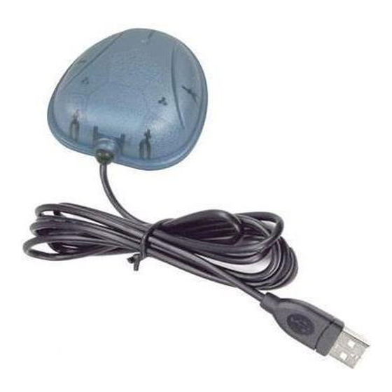
- Page 8 1. HI-204 Series Introductions HI-204 is a GPS receiver with PS/II mini-DIN interfaces and built-in active antenna for high sensitivity to tracking signal. HI-204 is well suited to system integration and users who use any kinds of mobile devices, such as, PDA, notebook PC, Tablet PC, etc.
-
Page 9: Optional Accessories
Optional Accessories: • PS/II to PDA connector and car charger • PS/II to DB9 adapting cable • PS/II to USB adapting cable HI-204 -USB HI-204 -XXXX (Pocket PC Plug) HI-204 -DB9... - Page 10 SECTION 1 INTRODUCTION 1.1 OVERVIEW Fast Acquisition Enhanced Sensitivity 20 Channels “All-In-View” Tracking GPS Sensor Module The receiver continuously tracks all satellites in view and provides accurate satellite positioning data. The HI-204 optimized for applications requiring good performance, low cost, and maximum flexibility; suitable for a wide range of OEM configurations including handhelds, sensors, asset tracking, PDA-centric personal navigation system, and vehicle navigation products.
- Page 11 Satellite-based augmentation systems, such as WAAS and EGNOS, are supported to yield improved accuracy. Both the LVTTL-level and RS232-level serial interface are provided on the interface connector. Supply voltage of 3.3V, or 3.8V~12V are supported. 1.2 Features • 20 parallel channel GPS receiver •...
-
Page 12: Section 2 Receiver Operation
SECTION 2 RECEIVER OPERATION Upon power up, after initial self-test has completed, the HI-204 will begin satellite acquisition and tracking process. Under normal open-sky condition, position-fix can be achieved within approximately 35 seconds (within 10 seconds if valid ephemeris data is already collected from recent use). - Page 13 As soon as GPS signal is acquired and tracked, the HI-204 will transmit valid navigation information through its serial interface. The navigation data contains following information: • Receiver position in latitude, longitude, and altitude • Receiver velocity • Time • DOP error-magnification factor •...
-
Page 14: Technical Specifications
2. Technical Specifications 2.1. Electrical Characteristics Items Description Chipset GSP3F SiRF StarIII technology Frequency L1, 1575.42 MHz General C/A code 1.023 MHz chip rate Channels 10 meters, 2D RMS Position 5 meters 2D RMS, WAAS corrected Accuracy <5meters(50%), DGPS corrected Velocity 0.1 meters/second Time... -
Page 15: Section 3 Hardware Interface
SECTION 3 HARDWARE INTERFACE 3.1 MECHANICAL DIMENSIONS Unit:mm Top View 69±0.2 I/O Cable Build-in patch antenna Lateral View 20±0.2 I/O Cable LED indicator Bottom View 69±0.2 I/O Cable Magnetic 73±0.2... -
Page 16: One-Pulse-Per-Second (1Pps) Output
3.2 ONE-PULSE-PER-SECOND (1PPS) OUTPUT one-pulse-per-second output provided applications requiring precise timing measurements. The output pulse is 1usec in duration. Rising edge of the output pulse is accurate to +/-1usec with respect to the start of each GPS second. Accuracy of the one-pulse-per-second output is maintained only when the GPS receiver has valid position fix. - Page 17 As long as enough satellite signals are received to generate valid position fixes, the 1PPS output remains synchronized to the GPS second, and the 1PPS Valid Signal remains active. If signal blockage prevents the receiver from generating valid position fix, the 1PPS output will drift away from the GPS second and the 1PPS Valid Signal will become inactive.
-
Page 18: Section 4 Software Interface
SECTION 4 SOFTWARE INTERFACE This section describes the details of the serial port commands through which the HI-204 is controlled and monitored. The serial port commands allow users to set the receiver parameters, configure output message type, and retrieve status information. The baud rate and protocol of the host COM port must match the baud rate and protocol of the GPS receiver serial port for commands and data to be successfully transmitted and received. -
Page 19: Gga - Gps Fix Data
4.1.1 NMEA Messages The serial interface protocol is based on the National Marine Electronics Association's NMEA 0183 ASCII interface specification. This standard is fully define in "NMEA 0183, Version 3.01" The standard may be obtained from NMEA, www.nmea.org 4.1.2 GGA - GPS FIX DATA Time, position and position-fix related data (number of satellites in use, HDOP, etc.). - Page 20 Field Example Description 104549.04 UTC time in hhmmss.ss format, 000000.00 ~ 235959.99 2447.2038 Latitude in ddmm.mmmm format Leading zeros transmitted Latitude hemisphere indicator, 'N' = North, 'S' = South 12100.4990 Longitude in dddmm.mmmm format Leading zeros transmitted Longitude hemisphere indicator, 'E' = East, 'W' = West Position fix quality indicator 0: position fix unavailable...
-
Page 21: Gll - Latitude And Longitude, With Time Of Position Fix And Status
4.1.3 GLL - LATITUDE AND LONGITUDE, WITH TIME OF POSITION FIX AND STATUS Latitude and longitude of current position, time, and status. Format: $GPGLL,<1>,<2>,<3>,<4>,<5>,<6>,<7>*<8><CR><LF> Example: $GPGLL,2447.2073,N,12100.5022,E,104548.04,A, A*65<CR><LF> Field Example Description 2447.2073 Latitude in ddmm.mmmm format Leading zeros transmitted Latitude hemisphere indicator, 'N' = North, 'S' = South 12100.5022 Longitude in dddmm.mmmm format... -
Page 22: Gsa - Gps Dop And Active Satellites
4.1.4 GSA - GPS DOP AND ACTIVE SATELLITES GPS receiver operating mode, satellites used for navigation, and DOP values. Format: $GPGSA,<1>,<2>,<3>,<3>,<3>,<3>,<3>,<3>,<3>,<3>, <3>,<3>,<3>,<3>,<4>,<5>,<6>*<7><CR><LF> Example: $GPGSA,A,3,26,21,,,09,17,,,,,,,10.8,02.1,10.6*07<CR><LF> Field Example Description Mode, 'M' = Manual, 'A' = Automatic Fix type, 1 = not available, 2 = 2D fix, 3 = 3D fix 26,21,,,09, PRN number, 01 to 32, of satellite... -
Page 23: Gsv - Gps Satellite In View
4.1.5 GSV - GPS SATELLITE IN VIEW Number of satellites in view, PRN number, elevation angle, azimuth angle, and C/No. Only up to four satellite details are transmitted per message. Additional satellite in view information is sent in subsequent GSV messages. Format: $GPGSV,<1>,<2>,<3>,<4>,<5>,<6>,<7>, ... -
Page 24: Rmc - Recommanded Minimum Specific Gps/Transit Data
4.1.6 RMC - RECOMMANDED MINIMUM SPECIFIC GPS/TRANSIT DATA Time, date, position, course and speed data. Format: $GPRMC,<1>,<2>,<3>,<4>,<5>,<6>,<7>,<8>,<9>,<10>, <11>,<12>*<13><CR><LF> Example: $GPRMC,104549.04,A,2447.2038,N,12100.4990,E, 016.0,221.0,250304,003.3,W,A*22<CR><LF> Field Example Description 104549.04 UTC time in hhmmss.ss format, 000000.00 ~ 235959.99 Status, 'V' = navigation receiver warning, 'A' = valid position 2447.2038 Latitude in dddmm.mmmm format Leading zeros transmitted... -
Page 25: Vtg - Course Over Ground And Ground Speed
4.1.7 VTG - COURSE OVER GROUND AND GROUND SPEED Velocity is given as course over ground (COG) and speed over ground (SOG). Format: GPVTG,<1>,T,<2>,M,<3>,N,<4>,K,<5>*<6><CR><LF> Example: $GPVTG,221.0,T,224.3,M,016.0,N,0029.6,K,A*1F<CR><LF> Field Example Description 221.0 True course over ground, 000.0 ~ 359.9 degrees 224.3 Magnetic course over ground, 000.0 ~ 359.9 degrees 016.0 Speed over ground,... -
Page 26: Default Values
APPENDIX B DEFAULT VALUES The product has the following factory preset default values: Datum: 000 (WGS-84) NMEA Enable Switch: ( 1 sec. output) ( 5 sec. output) ( 5 sec. output) ( 1 sec. output) ( 1 sec. output) Checksum ON Baud Rate: 4800 Baud Elevation Mask:... -
Page 27: Troubleshooting
TROUBLESHOOTING Problem Reasons Solutions No Position Weak or no GPS signal Place the HI-204 under an output but can be received at the open space, then, press timer is place of HI-204 unit 'Reset' counting At outdoor space but To try again, go to outdoor and GPS signal is blocked press 'Reset' or connect by building or car roof... -
Page 32: W A T E R P R O O F
W A T E R P R O O F W A T E R P R O O F G P S R e c e i v e r G P S R e c e i v e r...