Table of Contents
Advertisement
Cisco Small Business Pro
Cisco Unified Communications 500 Series
Model UC 540
Package Contents
• Cisco Unified Communications 500 Series Model UC 540
• 4 rubber mounting feet for desktop installation
• Ethernet cable (yellow RJ-45 to RJ-45)
• Console cable (light blue RJ-45 to DB9)
• Power cord and external power supply
• Wall-mount bracket for power supply
• Quick Start Guide
• Product CD-ROM
Quick Start Guide
Advertisement
Table of Contents

Related Manuals for Cisco UC540W-BRI-K9 - Uc System With 2BRI 1VIC Exp


Summary of Contents for Cisco UC540W-BRI-K9 - Uc System With 2BRI 1VIC Exp
-
Page 1: Quick Start Guide
Quick Start Guide Cisco Small Business Pro Cisco Unified Communications 500 Series Model UC 540 Package Contents • Cisco Unified Communications 500 Series Model UC 540 • 4 rubber mounting feet for desktop installation • Ethernet cable (yellow RJ-45 to RJ-45) •... - Page 2 Welcome Thank you for choosing the Cisco Unified Communications Model 540. The UC 540, part of the Cisco Smart Business Communications System (SBCS), is a unified communications solution for small businesses that provides voice, data, video, security, and wireless capabilities for 8 to 32 employees.
-
Page 3: Before You Begin
Before You Begin Before you begin the installation, make sure that you have the following: For Hardware Installation: • Cisco IP phones • (Optional) One or more Power over Ethernet (PoE) switches for connecting IP phones or computers. We recommend that you use Cisco ESW 500 Series switches. - Page 4 For Software Installation: • A PC running: – Windows Vista Ultimate, or Window XP (Service Pack 1) operating system – Microsoft Internet Explorer 6.0 or later – Adobe Flash Player with add-on version 10.0.0 or later • A registered account on Cisco.com. You need this so that you can download the CCA software necessary to configure your UC 540.
-
Page 5: Getting To Know The Uc 540
Getting to Know the UC 540 The UC 540 includes these features: • 8 switched 10/100 Power-over-Ethernet (PoE) ports • 4 Phone (FXS) ports • 4 Line (FXO) ports or 2 ISDN (BRI) ports for Public Switched Telephone Network (PSTN) connections •... -
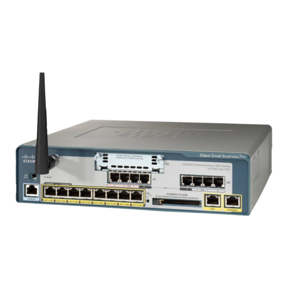
Page 6: Front Panel
Front Panel The front panel is where you connect the IP phones and other network devices. The ports on the panel vary depending on the model. There are two UC 540 Series model numbers: • UC540W-FXO-K9—Base model with 8 user license, integrated Wi-Fi, 4 Line (FXO) ports, and 1 VIC expansion slot •... - Page 7 Cisco UC 540 with Line (BRI) ports Line Wi-Fi VIC Slot (BRI) Phone (FXS) Ports antenna Ports Cisco Small Business Pro Unified Communications 500 Series UC540 with BRI Music on WLAN Hold POWER ETHERNET COMPACT FLASH CONSOLE PWR LNK PWR LNK PWR LNK PWR LNK PWR LNK...
-
Page 8: Back Panel
Line (FXO) ports Connects your phone system to the PSTN. Only applies to model UC540W-FXO-K9. If the power fails, you can still make and receive emergency calls if you have a telephone line connected to the Line (FXO) port 0 and an analog phone connected to the Phone (FXS) port 3, even if the unit is not powered on. - Page 9 LEDs The LEDs on the front panel of the UC 540 are used for monitoring system activity and performance. WLAN POWER ETHERNET WLAN POWER ETHERNET CONSOLE PWR LNK PWR LNK PWR LNK PWR LNK PWR LNK PWR LNK PWR LNK PWR LNK PWR LNK PWR LNK...
-
Page 10: Installing The Uc 540
Installing the UC 540 Regulatory Compliance and Before you install the UC 540, review the Safety Information for Cisco Unified Communications 500 Series for Small Business on your product CD. Only install supported Voice Interface Cards (VICs) into the VIC expansion slot of the UC 540. - Page 11 To mount the chassis and power supply on a wall, follow these steps: Align the mounting-screw holes with a wall stud, or use wall anchors. • For attaching to a wall stud, use two number-10 wood screws (round- or pan-head) with number-10 washers, or two number-10 washer-head screws.
-
Page 12: Grounding The Chassis
Attach the power supply bracket to the wall. The following illustration shows the wall-mount bracket for the power supply and the mounting-screw holes on the back of the bracket. Mounting screws (2) Attach the bracket to the wall by using the mounting hardware specified in Step b. - Page 13 Crimp the ground wire to the ground lug or ring terminal, using a crimp tool of the appropriate size. Attach the ground lug or ring terminal to the chassis. Tighten the screws to a torque of 8-10 in-lb. (0.9-1. 1 N-m). Ground Lug Connect the other end of the ground wire to a known reliable earth ground point.
-
Page 14: Connecting The Equipment
Connecting the Equipment Insert the power cord into the back of the UC 540. Do not connect to power. Screw the antenna onto the threaded connector on the front panel. Orient the antenna to point upward. Connect the interfaces and devices as described below. Type of Connection Description DSL, cable modem, or... - Page 15 Power on the UC 540 by inserting the power cord plug into a power outlet. There is no external Power On/Off switch on the unit. Power on the connected devices. ESW 500 Series Switch PSTN Cisco Small Business Pro Unified Communication 500 Series UC540 with FXO 192.168.10.1 WLAN...
-
Page 16: Verifying The Hardware Installation
Verifying the Hardware Installation To verify the hardware installation, complete the following tasks: • Check the status of the UC 540 by looking at the LEDs on the front panel LEDs, page • Check that the devices connected to the PoE ports are all receiving power. -
Page 17: Getting Started With The Configuration
Getting Started with the Configuration After you install the UC 540, you configure it by using Cisco Configuration Assistant (CCA). CCA is an easy to-use application used to configure, manage, and administer your UC 540 and other devices in the Cisco Smart Business Communications System. -
Page 18: Connecting To The Uc 540
Connecting to the UC 540 This section describes how to connect your PC to the UC 540 and how to use CCA to connect to the UC 540. Before you connect your PC, do the following: • Disable all network interface Cards (NICs) that are not directly connected to the UC 540. -
Page 19: Using The Telephony Setup Wizard
Enter 192.168.10.1 in the Starting IP Address field. This is the default IP address for the UC 540. Click Start. When prompted, enter the username and password for the UC 540 and click OK. The default username is cisco and the default password is cisco. Passwords are case sensitive. - Page 20 Click Next and follow the prompts to complete the installation. After the wizard completes: • Verify Internet connectivity by going to: http://www.cisco.com. • Test calls to and from the PSTN. • Test calls to voice mail and Auto Attendant (AA), if configured. •...
-
Page 21: Suggested Next Steps
Suggested Next Steps You are now ready to start using your UC 540. Depending on how you plan to use the UC 540 in your network, here are some suggested next steps to take. Implementing a Small Business Network Solution Use Cisco Smart Designs to plan and implement a Small Business network solution. -
Page 22: Where To Go From Here
Where to Go From Here Support Cisco Small Business http://www.cisco.com/go/smallbizsupport Support Community Online Technical Support http://www.cisco.com/support and Documentation (Login Required) Phone Support Contacts http://www.cisco.com/en/US/support/ tsd_cisco_small_business_support_center_contacts .html Software Downloads Go to http://www.cisco.com/public/sw-center/ (Login Required) index.shtml and enter the model number in the Software Search box. - Page 23 Americas Headquarters Cisco Systems, Inc. 170 West Tasman Drive San Jose, CA 95134-1706 http://www.cisco.com Tel: 408 526-4000 800 553-NETS (6387) Fax: 408 527-0883 Cisco, Cisco Systems, the Cisco logo, and the Cisco Systems logo are registered trademarks or trademarks of Cisco Systems, Inc. and/or its affiliates in the United States and certain other countries.