NETGEAR RN12P0610 - ReadyNAS 3200 Hardware Manual
Network attached storage system
Hide thumbs
Also See for RN12P0610 - ReadyNAS 3200:
- Installation manual (2 pages) ,
- Software manual (114 pages) ,
- Installation manual (2 pages)

Related Manuals for NETGEAR RN12P0610 - ReadyNAS 3200


Summary of Contents for NETGEAR RN12P0610 - ReadyNAS 3200
- Page 1 ReadyNAS 3200 Hardware Manual NETGEAR, Inc. 350 East Plumeria Drive San Jose, CA 95134 USA 202-10541-01 v1.1 July 2009...
-
Page 2: Technical Support
In the interest of improving internal design, operational function, and/or reliability, NETGEAR reserves the right to make changes to the products described in this document without notice. NETGEAR does not assume any liability that may occur due to the use or application of the product(s) or circuit layout(s) described herein. - Page 3 Product and Publication Details Model Number: 3200 Publication Date: July 2009 Product Family: Network Storage Product Name: ReadyNAS 3200 Network Attached Storage System Home or Business Product: Business Language: English Publication Part Number: 202-10541-01 Publication Version Number: v1.1, July 2009...
- Page 4 v1.1, July 2009...
-
Page 5: Table Of Contents
Contents About This Manual Conventions and Formats ....................vii User Manual Revision History ..................viii Chapter 1 Getting Started Control Panel, Status Displays, Ports, and Drive Bays ..........1-1 Front Panel .......................1-1 Disk Tray, Status Lights, Release, and Tray Handle, ..........1-2 Rear Panel .......................1-3 Safety Warning .......................1-3 Rack Mount Setup ......................1-4 Rack Mounting Considerations ................1-4... - Page 6 Adding or Replacing Disks ................... 2-11 Adding a New Disk ....................2-11 Failed Disk Notification ...................2-13 Choosing a Replacement Disk ................2-13 Replacing a Failed Disk ..................2-13 Replacing System Components ...................2-15 Accessing the Inside of the System ...............2-15 Replacing a System Fan ..................2-16 Replacing a Power Supply ..................2-18 Replacing the Onboard Battery ................2-19 Appendix A...
-
Page 7: About This Manual
About This Manual The NETGEAR® ReadyNAS 3200 Hardware Manual describes the hardware features of a ReadyNAS 3200 system. It also provides procedures for using the system diagnostics boot menu, and procedures for adding, replacing or formatting disks. The information in this manual is intended for readers with intermediate computer and networking skills. -
Page 8: User Manual Revision History
ReadyNAS 3200 Hardware Manual Danger: This safety warning warns against personal injury or death. User Manual Revision History Version Publication Part Number Description Number Date 202-10541-01 June 2009 First publication 202-10541-01 July 2009 Updated with safety compliance information and component replacement topics. -
Page 9: Getting Started
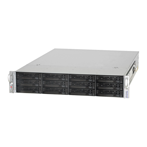
ReadyNAS 3200 Hardware Manual Chapter 1 Getting Started This chapter provides an overview of the unit’s physical features. Topics discussed in this chapter include: • “Control Panel, Status Displays, Ports, and Drive Bays” • “Safety Warning” • “Initial Setup, Default IP Address, and Login Password” •... -
Page 10: Disk Tray, Status Lights, Release, And Tray Handle
ReadyNAS 3200 Hardware Manual Disk Tray, Status Lights, Release, and Tray Handle Disk present and activity light Disk failure light Figure 1-2 The disk tray features a push switch activated pop-out tray handle. Disk tray handle Disk tray release push switch Figure 1-3 Warning: Regardless of how many hard drives are installed, all drive trays must remain in the drive bays to maintain proper airflow. -
Page 11: Rear Panel
ReadyNAS 3200 Hardware Manual Rear Panel Figure 1-4 1. Dual power supplies. 2. PS2 keyboard and mouse ports. 3. Two USB ports. 4. VGA monitor port. 5. RS232 console port. 6. Two gigabit Ethernet ports with failover and link aggregation. Safety Warning 1. -
Page 12: Rack Mount Setup
ReadyNAS 3200 Hardware Manual Rack Mount Setup Use the included rack mount hardware to install the unit according to the instructions below. Figure 1-5 Danger: A unit with installed drives can weigh more than eighty pounds. So as to avoid injury or damage to the equipment, plan to perform the rack mount installation with appropriate assistance. -
Page 13: Electrical Safety Precautions
ReadyNAS 3200 Hardware Manual Circuit Overloading Consideration should be given to the connection of the equipment to the power supply circuitry and the effect that any possible overloading of circuits might have on overcurrent protection and power supply wiring. Appropriate consideration of equipment nameplate ratings should be used when addressing this concern. -
Page 14: Electrostatic Discharge (Esd) Precautions
ReadyNAS 3200 Hardware Manual • The ReadyNAS 3200 weighs approximately 82lbs when fully loaded. When lifting the system, two people at either end should lift slowly with their feet spread out to distribute the weight. Always keep your back straight and lift with your legs. •... -
Page 15: Rack Mount Precautions
ReadyNAS 3200 Hardware Manual • Put the mainboard and peripherals back into their antistatic bags when not in use. • For grounding purposes, make sure your computer chassis provides excellent conductivity between the power supply, the case, the mounting fasteners and the mainboard. •... -
Page 16: Preparing For Setup
ReadyNAS 3200 Hardware Manual Preparing for Setup Read these instructions in their entirety before you begin. Locate the ReadyNAS 3200 shipping carton, remove the rack mounting kit and prepare to work with it. Installing the System into a Rack Follow these instructions for installing the system into a rack. 1. - Page 17 ReadyNAS 3200 Hardware Manual 3. Fasten the backs of the outer rails to the rack with screws. Press the release to extend the rails. Hang the hooks of the rails into the rack holes, and fasten the rails to the rack. Figure 1-7 4.
-
Page 18: Initial Setup, Default Ip Address, And Login Password
Initial Setup, Default IP Address, and Login Password Follow the instructions in the NETGEAR Installation Guide that came with your unit to install it. An electronic copy of the installation guide is on the product CD, on the NETGEAR web site, and on http://readynas.com. -
Page 19: Diagnostics And Maintenance
Chapter 2 Diagnostics and Maintenance This chapter includes topics on system status, system shutdown, using the diagnostics menu, and adding, replacing, or formatting disks. • “Identifying Control Panel Diagnostic and Status Information” • “Performing System Shutdown” • “Understanding the System Diagnostics Boot Menu” •... - Page 20 ReadyNAS 3200 Hardware Manual The function of each control panel item is described in the following table: Table 2-1. Description of control panel items Item Activity Description Power Push to turn on the ReadyNAS 3200.The power LED blinks Switch. Push button while the ReadyNAS 3200 is booting.
-
Page 21: Performing System Shutdown
ReadyNAS 3200 Hardware Manual Table 2-1. Description of control panel items (continued) Item Activity Description Power diagnostic On (Red) On red: power failure. Off: normal operation. FAN LED On (Red) On red: Overheating or fan failure. Off: normal operation. Upper disk tray On (Green) On: Disk installed. -
Page 22: Using The Frontview Browser User Interface
ReadyNAS 3200 Hardware Manual Using the FrontView Browser User Interface The FrontView System > Shutdown Options screen offers the option to power off or reboot the ReadyNAS 3200. You also have the option of performing a full file system check or a quota check on the next boot. -
Page 23: Understanding System Diagnostics Boot Menu
ReadyNAS 3200 Hardware Manual 1. Boot menu enabled: use the Reset button to scroll through the menu to select an option. Note: The boot menu defaults to Normal Boot if no selection is made after three seconds. 2. Normal boot: perform a normal boot. 3. - Page 24 ReadyNAS 3200 Hardware Manual 1. While using a paper clip or push pin to gently press in the reset switch, power on the unit. Wait for the two red boot menu status lights on the front to display, then release the reset switch. Control Panel Boot Menu Options Boot Menu Sequence...
-
Page 25: Using The Boot Menu To Format A Raid Volume
ReadyNAS 3200 Hardware Manual Using the Boot Menu to Format a RAID Volume Warning: Using the Factory Default boot menu option will erase all the data on the hard disks. Do a full backup before using the Factory Default option. You can switch between the Expandable Volume (X-RAID2) mode and the Flexible Volume Flex-RAID 0/1/5/6) mode only if you want to change the default configuration. - Page 26 ReadyNAS 3200 Hardware Manual b. Hold the display of the final LEDs in the pattern (on on), and wait for you to confirm the selection. 4. Press and hold the reset button for 3 seconds to confirm the menu selection and proceed with that option.
- Page 27 ReadyNAS 3200 Hardware Manual 7. Click Setup to display the ReadyNAS Volume Setup screen. Figure 2-3 8. Select either the Expandable Volume (X-RAID2) or the Flexible Volume (Flex-RAID) radio button, configure the options accordingly, and click Create Volume Now. The volume and initialization process begins.
- Page 28 ReadyNAS 3200 Hardware Manual RAIDar shows that the system is initializing the volume. Figure 2-4 The system powers down when the volume initialization completes. 9. Power the system on. It will perform diagnostics while it boots. 10. Click Rescan in RAIDar to connect to the system. Figure 2-5 RAIDar will find the system and show that it is booting.
-
Page 29: Adding Or Replacing Disks
Adding or Replacing Disks Adding and replacing failed disks are similar processes. Note: Be sure to check the Hardware Compatibility list on the NETGEAR support site for a list of disks that have been qualified for the ReadyNAS 3200 to assure that you use a suitable disk. - Page 30 ReadyNAS 3200 Hardware Manual 2. Pull out the disk tray, and replace the failed disk. Figure 2-8 Make sure that the hard disk connectors face the interior of the disk bay when you reassemble the disk. 3. Slide the disk tray back into the ReadyNAS and secure the handle. The volume automatically synchronizes with the new disk in the background, taking several hours depending on the disk size.
-
Page 31: Failed Disk Notification
ReadyNAS 3200 Hardware Manual Failed Disk Notification When a disk fails in your ReadyNAS, you are notified of the failure by e-mail. The FrontView main menu Status > Health screen provides information about the failed disk. Figure 2-9 The disk tray of the ReadyNAS 3200 includes a failed disk LED that turns amber when its disk fails. - Page 32 ReadyNAS 3200 Hardware Manual 2. Pull the disk tray release pull switch. The disk tray handle pops out. Disk tray Failed disk LED handle Disk tray release pull switch Figure 2-10 3. Pull out the disk tray, and replace the failed disk. Figure 2-11 Make sure that the hard disk connectors face the interior of the disk bay when you reassemble the disk.
-
Page 33: Replacing System Components
ReadyNAS 3200 Hardware Manual Replacing System Components You can replace failed components such as power supplies, fans and the system battery. This section explains how to replace failed components. Accessing the Inside of the System You may need to access the inside of the system to replace failed components such as power supplies, fans or the system battery. -
Page 34: Replacing A System Fan
ReadyNAS 3200 Hardware Manual 3. You can then lift the top cover from the chassis to gain full access to the inside of the system. Figure 2-13 Warning: Care must be taken to assure that the chassis cover is in place when the system is operating to assure proper cooling. - Page 35 ReadyNAS 3200 Hardware Manual Follow these steps to replace a system fan. Note: System power does not need to be shut down since the fans are hot-pluggable. 1. Remove the chassis cover. 2. Press the tabs on the sides of the fan to unlock and remove the fan and its housing. The fan’s power connections will automatically detach.
-
Page 36: Replacing A Power Supply
ReadyNAS 3200 Hardware Manual Replacing a Power Supply The ReadyNAS 3200 has a 700 watt redundant power supply consisting of two power modules. Each power supply module has an auto-switching capability, which enables it to automatically sense and operate at a 100V - 240V input voltage. If either of the two power supply modules fail, the other module will take the full load and allow the system to continue operation without interruption. -
Page 37: Replacing The Onboard Battery
This battery must be replaced only with the same or an equivalent type recommended by the NETGEAR. Dispose of used batteries according to the manufacturer's instructions. Danger: There is a danger of explosion if the onboard battery is installed upside down, which will reverse its polarities. - Page 38 ReadyNAS 3200 Hardware Manual 2-20 Diagnostics and Maintenance v1.1, July 2009...
-
Page 39: Default Settings And Specifications
ReadyNAS 3200 Hardware Manual Appendix A Default Settings and Specifications This appendix provides the factory default settings and system specifications. You can reset all the ReadyNAS settings to its factory defaults. To return the ReadyNAS to the factory configuration settings shown, follow the instructions in “Using the OS Reinstall Option to Reinstall the Firmware”... - Page 40 ReadyNAS 3200 Hardware Manual The table below lists the system specifications. Table A-2. ReadyNAS 3200 System Specifications Feature Specification Electrical Power supplies (PSU) 2 700W server rated AC power supplies Input 100-240V AC, 50/60Hz Power consumption 170W typical with 6 TB disks Thermal Cooling Fans 3 80mm dual ball-bearing chassis cooling fans...