
Related Manuals for Yamaha EF6300iSDE - 5500 Watt Inverter Generator


Summary of Contents for Yamaha EF6300iSDE - 5500 Watt Inverter Generator
- Page 1 Generator OWNER’S MANUAL EF6300iSDE PLEASE READ AND UNDERSTAND THIS MANUAL LIT-19626-01-52 COMPLETELY BEFORE OPERATING THE MACHINE. 7CK-28199-10...
- Page 3 AE00002 INTRODUCTION Congratulations on your purchase of your new Yamaha. This manual will provide you with a good basic understanding of the operation and maintenance of this machine. If you have any questions regarding the operation or maintenance of your machine, please consult a Yamaha dealer.
- Page 4 If there is any question concerning this manu- al, please consult a Yamaha dealer. 9 This manual should be considered a A CAUTION indicates special precautions permanent part of this engine and...
-
Page 5: Table Of Contents
AE00041 CONTENTS SAFETY INFORMATION ......1 Starting the engine ......18 EXHAUST FUMES ARE Stopping the engine......20 POISONOUS........1 Connection .........21 Application range........23 FUEL IS HIGHLY FLAMMABLE AND POISONOUS........1 PERIODIC MAINTENANCE ....25 ENGINE AND MUFFLER MAY BE Maintenance chart ......25 HOT ............1 Spark plug inspection ......27 ELECTRIC SHOCK PREVENTION..2 Carburetor adjustment......28 CONNECTION NOTES ......3... -
Page 6: Safety Information
AE00071 SAFETY INFORMATION AE00072 EXHAUST FUMES ARE POISONOUS 9 Never operate the engine in a closed area or it 741-7XFa may cause unconsciousness and death within a short time. Operate the engine in a well ventilated area. AE00075 FUEL IS HIGHLY FLAMMABLE AND POISONOUS 9 Always turn off the engine when refuelling. -
Page 7: Electric Shock Prevention
9 Keep the machine at least 1 m (3 ft) from buildings or other equipment, or the engine may overheat. a 1 m (3 ft) 741-7XFg 9 Avoid operating the engine with a dust cover. 741-7XFh 9 Be sure to carry the generator only by its carrying handles 1. -
Page 8: Connection Notes
9 Connect the ground lead of the machine to the ground (earth) terminal 1 and connect the end to the ground electrode buried in the ground. 763-7CKa AE00088 CONNECTION NOTES 9 Avoid connecting the generator to commercial power outlet. 9 Avoid connecting the generator in parallel with any other generator. -
Page 9: Location Of Important Labels
AE00062 LOCATION OF IMPORTANT LABELS Please read the following labels carefully before oper- ating this machine. NOTE: Maintain or replace safety and instruction labels, as necessary. DANGER WARNING Using a generator indoors CAN KILL YOU IN MINUTES. Electrocution or property damage can occur: Do not connect this Generator exhaust contains carbon monoxide. - Page 10 Rated Use the specified spark plug only. Phase Single Fuel Gasoline Specified plug:BPR4ES(NGK) YAMAHA MOTOR POWERED PRODUCTS CO.,LTD. MADE IN JAPAN 7CK-24164-10 Important Emissions Information The air index of this engine is 3 (California only) YAMAHA MOTOR POWERED PRODUCTS CO.,LTD.
-
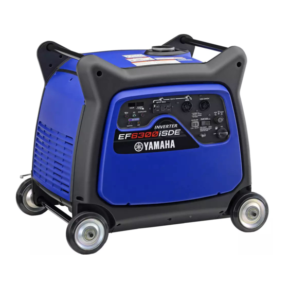
Page 11: Description
DESCRIPTION AE00102 1 Carrying handles (shaded) 2 Fuel tank cap 3 Fuel gauge 4 Muffler 5 Caster lock lever 6 Oil filler cap 7 Oil drain bolt 8 Battery 793-7CKa 793-7CKb AE00103 Control panel 1 Hour meter 2 Power meter 3 G.F.C.I. -
Page 12: Control Function
AE00101 CONTROL FUNCTION AE00121 Engine switch The engine switch controls the ignition system. 7 “ON” 763-119 Ignition circuit is switched on. The engine can be started. 5 “STOP” Ignition circuit is switched off. The engine will not run. 6 “START” Starting circuit is switched on. -
Page 13: Ac Protector
AE00134 AC protector The AC protector 1 trips when total amount of the receptacles 2 loads exceed 20A. The AC protector 3 trips when the receptacle 4 loads exceed 30A. 793-7CKe Press the switches to reset the AC protectors. “Set” 3 “Reset”... -
Page 14: G.f.c.i. Receptacle
AE00848 G.F.C.I. receptacle TO REDUCE THE CHANCE OF ELECTRICAL SHOCK: 9 Do not attempt to operate electric devices if the ground fault circuit interrupter reset button 763-083c pops out repeatedly during use. 9 Test the ground fault circuit interrupter during the pre-operation checks according to the maintenance instructions on page 36. -
Page 15: Hour Meter
NOTE: If you operate the generator with the voltage select switch in the 120/240V-position, the electric current will be limited for the 120V-receptacles. When you use either receptacle 1 or 2 AND recepta- cle 3 at the same time, the total electric current pro- 793-7CKf vided will be equal to or even less than 22.9A. -
Page 16: Overload Indicator Light (Red)
AE01087 Overload indicator light (red) The overload indicator light 1 comes on when an overload of a connected electrical device is detected, the inverter control unit overheats, or the AC output voltage rises. Then, the AC protector will trip, stopping power generation in order to protect the generator and 763-7CKd any connected electric devices. -
Page 17: Fuel Cock Knob
Fuel cock knob The fuel cock supplies fuel from the fuel tank to the carburetor. The fuel cock has two positions. 763-7CKb 1 “ ON” With the knob in this position, fuel flows to the carbure- tor. Normal using is done with the knob in this position. 2 “... -
Page 18: Preparation
Fuel tank capacity: Total: 17.0 L (3.17 US gal, 2.64 Imp gal) Your Yamaha engine has been designed to use regu- lar unleaded gasoline with a pump octane number ((R + M)/2) of 86 or higher, or research octane number of 91 or higher. -
Page 19: Engine Oil
AE00222 Engine oil The generator has been shipped without engine oil. Do not start the engine till fill with the suffi- cient engine oil. 1. Place the generator on a level surface. 2. Remove the bolts 1, and then pull outward on the areas of rear cover 2 shown. -
Page 20: Battery Preparation
AE01083 Battery preparation (See page 34) 9 Electrolyte is poisonous and dangerous since it contains sulfuric acid, which causes severe burns. Avoid any contact with skin, eyes or clothing and always shield your eyes when working near batteries. In case of contact, administer the following FIRST AID. - Page 21 8. Connect the negative lead (black) 8 to the nega- tive (-) battery terminal 9. 762-7CKd 9. Install the rear cover and tighten the bolts. – 16 –...
-
Page 22: Pre-Operation Check
9 Check oil level in engine. 9 If necessary, add recommended oil to specified level. 9 Check generator for oil leakage. The point where abnormality was recognized by 9 Check operation. 9 If necessary, consult a Yamaha dealer. – 17 –... -
Page 23: Operation
AE00846 OPERATION 9 Never operate the engine in a closed area or it may cause unconsciousness and death within 761-7CKb a short time. Operate the engine in a well ven- tilated area. 9 Before starting the engine, do not connect any electric devices. - Page 24 2. Turn the engine switch to “ON”. 7 “ON” 763-127h 3. Turn the engine switch to “START”. Take your hand off the switch immediately after the engine starts. 6 “START” 763-120a If the engine fails to start, release the switch, wait a few seconds, then try again.
-
Page 25: Stopping The Engine
AE00840 Stopping the engine 1. Turn off any electric devices. 2. Disconnect any electric devices. 761-7CKb 3. Turn the engine switch to “STOP”. 5 “STOP” 763-120b 4. Turn the fuel cock knob to “OFF”. 1 “OFF” 705-073a – 20 –... -
Page 26: Connection
AE00839 Connection Alternating Current (AC) Be sure any electric devices are turned off before plugging them in. 9 Be sure all electric devices including the lines and plug connections are in good condition before connection to the generator. 9 Be sure the total load is within generator rated output. - Page 27 4. Make sure the AC pilot light 1 is on. 763-7CKc 5. Turn the economy control switch to “ON” “ON” ECON.SW å Economy control switch 763-124c 6. Turn on any electric devises. NOTE: The economy control switch must be turned to “OFF” to increase engine speed to rated rpm.
-
Page 28: Application Range
AE00812 Application range When using the generator, make sure the total load is within rated output of a generator. Otherwise, generator damage may occur. 0.4 ~ 0.75 Power factor 0.8 ~ 0.95 (Efficiency 0.85) EF6300iSDE – 5,500W – 4,400W – 1,870W NOTE: 9 “–”... - Page 29 — MEMO — – 24 –...
-
Page 30: Periodic Maintenance
The most impor- tant points of generator inspection, adjustment, and lubrication are explained on the fol- lowing pages. If you are not familiar with maintenance work, have a Yamaha dealer do it for you. AE00403 Maintenance chart Stop the engine before starting maintenance work. - Page 31 *1·····Initial replacement of the engine oil is after one month or 20 hours of operation. *2·····The air filter element needs to be cleaned more frequently when using in unusually wet or dusty areas. ★····· Since these items require special tools, data and technical skills, have a Yamaha dealer perform the ser- vice.
-
Page 32: Spark Plug Inspection
AE01051 Spark plug inspection The spark plug is important engine components, which should be checked periodically. 1. Remove the bolts 1, and then pull outward on the areas of front cover 2 shown. 788-7CKa 2. Remove the spark plug cap and then remove the spark plug. -
Page 33: Carburetor Adjustment
AE00431 Carburetor adjustment The carburetor is a vital part of the engine. Adjusting should be left to a Yamaha dealer with the profession- al knowledge, specialized data, and equipment to do so properly. AE00412 Engine oil replacement Avoid draining the engine oil immediately after stopping the engine. -
Page 34: Air Filter
7. Add engine oil to the upper level 1. Recommended engine oil: å YAMALUBE 4 (10W-40), SAE 10W-30 or 10W-40 ∫ SAE #30 700-006a ç SAE #20 ∂ SAE 10W 0°C 25°C Recommended engine oil grade: å YAMALUBE 4 (10W-40) API Service SE type or higher Engine oil quantity: 1.3 L (1.37 US qt, 1.14 lmp qt) - Page 35 3. Remove the air filter cover 1 and foam element 4. Wash the foam element in solvent and dry it. 5. Oil the foam element and squeeze out excess oil. The foam element should be wet but not dripping. Recommended oil: Foam-air-filter oil SAE #20 motor oil Do not wring out the foam element when squeez-...
-
Page 36: Muffler Screen And Spark Arrester
AE01075 Muffler screen and spark arrester The engine and muffler will be very hot after the engine has been run. 741-7XFl Avoid touching the engine and muffler while they are still hot with any part of your body or clothing during inspection or repair. - Page 37 3. Remove the carbon deposits on the muffler screen and spark arrester using a wire brush. When cleaning, use the wire brush lightly to avoid damaging or scratching of the muffler screen and 711-075 spark arrester. 4. Check the muffler screen and spark arrester. Replace them if damaged.
-
Page 38: Fuel Tank Filter
AE00471 Fuel tank filter Never use or be near the fuel and solvent while smoking or in the vicinity of an open flame. 1. Remove the fuel tank cap and filter 1. 2. Clean the filter with gasoline. If damaged, replace it. 3. -
Page 39: Battery
9 KEEP THIS AND ALL BATTERIES OUT OF THE REACH OF CHILDREN. To charge the battery Have a Yamaha dealer charge the battery as soon as possible if it seems to have discharged. AE01057 Recommended battery Recommended battery: Capacity: 12V/18Ah –... -
Page 40: Fuse Replacement
2 shown. 788-7CKa 2. Replace the fuse with one of proper amperage. Specified fuse: 20A NOTE: If the fuse immediately blows again, consult a Yamaha 779-7XF dealer. 3. Install the front cover and tighten the bolts. – 35 –... -
Page 41: G.f.c.i. Receptacle Test
3. If G.F.C.I. operation is correct, push in the reset button. If the G.F.C.I. operates incorrectly, consult a Yamaha dealer. Do not operate the generator with a faulty G.F.C.I. circuit. Electric shock could occur. Have the gen- erator repaired by a qualified mechanic. -
Page 42: Storage
AE00601 STORAGE Long term storage of your machine will require some preventive procedures to guard against deterioration. AE01056 Drain the fuel 1. Turn the engine switch to “STOP” 1. 2. Remove the fuel tank cap. Extract the fuel from the fuel tank into an approved gasoline container using a commercially available handsiphon. - Page 43 6. Remove the bolts 1, and then pull outward on the areas of front cover 2 shown. 788-7CKa 7. Drain the fuel from the carburetor by loosening the drain screw 1 on the carburetor float chamber. 8. Turn the engine switch to “OFF”. 9.
-
Page 44: Engine
AE00889 Engine Perform the following steps to protect the cylinder, pis- ton ring, etc. from corrosion. 1. Remove the spark plug cap and spark plug, pour about one tablespoon of SAE 10W30 or 20W40 motor oil into spark plug hole and reinstall the spark plug only. -
Page 45: Battery
AE01086 Battery 1. Remove the battery. 2. Store the battery in a cool, dark and dry place. Do not store the battery in an excessively warm or cold place [i.e., less than 0°C (30°F) or more than 762-003 30°C (90°F)]. 9 Disconnect the negative lead (black) first, then the positive lead (red) from the battery. - Page 46 — MEMO — – 41 –...
-
Page 47: Troubleshooting
2 Engine switch to “START” 1. Poor spark 2 Spark plug dirty with carbon or wet ..Remove carbon or wipe spark plug dry. 2 Faulty ignition system ..Consult a Yamaha deal- 763-120a 4. Compression Insufficient 2 Worn out piston and cylinder ..Consult a Yamaha dealer. -
Page 48: Generator Won't Produce Power
M Engine does not start. Engine starts. Check the following Clean or Replace; Consult a Clogged Yamaha dealer. 9 Fuel cock clogging 9 Air cleaner element Consult a Yamaha dealer. clogging. – 43 –... - Page 49 Faulty battery and/or starter motor. Consult a Yamaha dealer. Check engine oil level. Level low Consult a Add engine oil. Yamaha dealer. O Check the spark plug. 9 Type: 9 Gap: Incorrect Replace or Clean the spark Adjust gap. plug.
-
Page 50: Specifications
AE00701 SPECIFICATIONS AE00702 Dimensions Unit EF6300iSDE Overall Length mm (in) 780 (30.7) Overall Width mm (in) 616 (24.3) Overall Height mm (in) 692 (27.2) Dry Weight kg (lb) 91 (200) AE00704 Engine Unit EF6300iSDE Type Air cooled 4-stroke gasoline OHV Cylinder Arrangement Inclined, 1 cylinder Displacement... -
Page 51: Consumer Information
PRI-I.D. NUMBER: AE00012 Identification number records Record your Primary I.D., and serial num- MODEL bers in the spaces provided, to assist you in ordering spare parts from a Yamaha dealer. PRI-I.D. Also record and keep these I.D. numbers CODE SERIAL No. -
Page 52: Limited Warranty (Ef- And Edl-Series)
RANTIES OF MERCHANTABILITY AND FITNESS authorized Yamaha consumer generator dealer FOR A PARTICULAR PURPOSE WHICH EXCEED will, free of charge, repair or replace, at Yamaha’s THE OBLIGATIONS AND TIME LIMITS STATED IN option, any part adjudged defective by Yamaha THIS WARRANTY ARE HEREBY DISCLAIMED BY due to faulty workmanship or material from the YAMAHA MOTOR CORPORATION, U.S.A. - Page 53 Yamaha Motor exactly as specified in the Owner’s Manual? Corporation, U.S.A. by the selling dealer at the A. No. The warranty on a new Yamaha cannot time of your purchase. If you should move after be “voided” or “cancelled.”...
-
Page 54: Exhaust Emission Control System And Components
ROAD ENGINES. The acronyms conform to the latest version of the SAE’s recommended practice docu- ment J1930, “Diagnostic Acronyms, Terms, and Definitions For Electrical/Electronic System”. It is recommended that these items be serviced by a Yamaha dealer. – 49 –... - Page 55 — MEMO — – 50 –...
-
Page 56: Wiring Diagram
– 51 –... - Page 57 – 52 –...
- Page 58 — MEMO — – 53 –...
- Page 60 PRINTED IN JAPAN 09 – 1.0 × 1 PRINTED ON RECYCLED PAPER 2008...