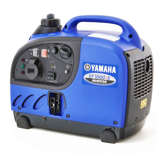
Yamaha EF1000iS Service Manual
900 running watts/1000 starting watts, gas powered portable inverter, carb compliant
Hide thumbs
Also See for EF1000iS:
- Owner's manual (140 pages) ,
- Theory & diagnostics manual (218 pages) ,
- Owner's manual (100 pages)
Table of Contents
Advertisement
Quick Links
Advertisement
Table of Contents
Troubleshooting

Related Manuals for Yamaha EF1000iS


Summary of Contents for Yamaha EF1000iS
- Page 1 SERVICE MANUAL EF1000iS LIT-19616-01-02 7VV-28197-10 310137...
- Page 2 www.carburetor-manual.com Thank you for buying this manual from me! I appreciate your business and hope that you come back again. Please do not share this on the internet, as while we do not make a lot at this, it is what I do full time to support my family from here in the Philippines.
- Page 3 FOREWORD HOW TO USE THIS MANUAL This manual was written by the Yamaha Motor PARTICULARLY IMPORTANT Company primarily for use by Yamaha dealers INFORMATION and their qualified mechanics. It is not possible to put an entire mechanic’s education into one...
- Page 4 Apply gear oil u Apply molybdenum disulfide oil i Apply wheel bearing grease o Apply lightweight lithium-soap base grease p Apply molybdenum disulfide grease a Apply a locking agent (LOCTITE ® s Apply Yamaha bond d Use a new one...
- Page 5 INDEX GENERAL INFORMATION INFO PERIODIC INSPECTIONS AND ADJUSTMENTS INSP ENGINE CARBURETOR CARB ELECTRICAL ELEC TROUBLESHOOTING TRBL SPECIFICATIONS SPEC...
-
Page 6: Table Of Contents
CHAPTER 1. PILOT LIGHT ........2-15 RECEPTACLE ......... 2-16 GENERAL INFORMATION DC CIRCUIT BREAKER ....2-16 MACHINE IDENTIFICATION ....1-1 CHAPTER 3. SERIAL NUMBER........1-1 STARTING SERIAL NUMBER.....1-1 ENGINE IMPORTANT INFORMATION ....1-2 CONTROL BOX ........3-1 PREPARATION FOR REMOVAL AND CONTROL BOX DISASSEMBLY ..3-2 DISASSEMBLY CONTROL BOX ASSEMBLY ..... - Page 7 CRANKSHAFT INSTALLATION ..3-27 CHAPTER 6. TROUBLESHOOTING CYLINDER (CRANKCASE 1) AND VALVE ........... 3-29 ENGINE ..........6-1 VALVE AND VALVE SPRING REMOVAL ........3-31 THROTTLE CONTROL SYSTEM ..6-6 VALVE AND VALVE SPRING INSPECTION ........3-31 CHAPTER 7. VALVE SEAT INSPECTION .... 3-33 SPECIFICATIONS CYLINDER (CRANKCASE 1) INSPECTION ........
-
Page 8: Chapter 1. General Information
MACHINE IDENTIFICATION INFO GENERAL INFORMATION MACHINE IDENTIFICATION SERIAL NUMBER The serial number is printed on a label 1 which is affixed to the generator as shown. NOTE: The first three characters of this number are for model identification, the remaining digits are the unit production number. -
Page 9: Important Information
Be sure to use the correct special tool for the job to guard against damage. SVU1040 2. Oil, grease and seals Be sure to use genuine Yamaha oils, grease and sealers, or the equivalents. SVU1050 3. Expendable parts Always replace the gaskets, O-rings, cotter pins and circlips with new parts when servicing engine. -
Page 10: All Replacement Parts
IMPORTANT INFORMATION INFO ALL REPLACEMENT PARTS We recommend the use of genuine Yamaha parts for all replace- ments. Use oil and/or grease, recommended by Yamaha, for assembly and adjustment. GASKETS, OIL SEALS, AND O-RINGS 1. All gaskets, seals, and O-rings should be replaced when an engine is overhauled. -
Page 11: Special Tools And Testers
SPECIAL TOOLS AND TESTERS INFO SPECIAL TOOLS AND TESTERS The proper special tools are necessary for complete and accurate tune-up and assembly. Using the correct special tool will help pre- vent damage caused by the use of improper tools or improvised techniques. - Page 12 SPECIAL TOOLS AND TESTERS INFO 7. Rotor puller 1 P/N. YU-33270 2 P/N. 90890-01362 This tool is necessary for removing the magneto rotor. SVU1210 SVU1220 8. Pocket tester P/N. YU-03112, 90890-03112 This instrument is necessary for checking the electrical system. SVU1230 9.
- Page 13 INFO...
-
Page 14: Periodic Inspections And Adjustments
INTRODUCTION/MAINTENANCE INTERVALS CHART/ INSP PERIODIC MAINTENANCE/LUBRICATION INTERVALS PERIODIC INSPECTIONS AND ADJUSTMENTS INTRODUCTION This chapter includes all information necessary to perform recommended inspections and adjust- ments. These preventive maintenance procedures, if followed, will ensure more reliable machine operation and a longer service life. The need for costly overhaul work will be greatly reduced. This information applies to machines already in service as well as new machines that are being prepared for sale. - Page 15 INSP PERIODIC MAINTENANCE/LUBRICATION INTERVALS Initial Every Pre-Ope- ration Item Remarks check month months months months (daily) or 20 Hr or 50 Hr or 100 Hr or 300 Hr 13. Generation Check the pilotlight comes on. Fittings/ Check all fittingsand fasteners. Fasteners Correct if necessary.
-
Page 16: Covers
INSP COVERS COVERS 6 Nm (0.6 m · kg, 4.3 ft · lb) Order Job name Q’ty Remarks Cover 2, cover 3, side cover 2, Remove the parts in the order listed rear cover, front cover removal below. Cover 2 Cover 3 Side cover 2 Rear cover... -
Page 17: Engine
ENGINE OIL LEAKAGE CHECKING/ INSP OIL LEVEL CHECKING ENGINE ENGINE OIL LEAKAGE CHECKING 1. Remove: 9 Cover 3 9 Side cover 2 9 Side cover 2. Check the areas outside of the engine for oil leakage. Oil leakage → Replace the gasket, oil seal, or O-ring. -
Page 18: Oil Replacement
INSP OIL REPLACEMENT OIL REPLACEMENT 1. Warm up the engine for several minutes. 2. Stop the engine. 3. Remove: 9 Drain joint 1 9 Cover 3 Remove the drain joint from the mount base. 4. Place a receptacle under the engine. 5. -
Page 19: Fuel Leakage
FUEL LEAKAGE/ INSP FUEL TANK FILTER FUEL LEAKAGE 1. Remove: 9 Cover 3 2. Check: 9 Leakage Check at fuel tank, fuel pump, fuel cock, fuel hose, and carburetor. Replace hose every four years. FUEL TANK FILTER Do not smoke, and keep away form open flames, sparks, or any other source of fire when handling or in the vicinity of fuel. -
Page 20: Fuel Tank Strainer
INSP FUEL TANK STRAINER FUEL TANK STRAINER Do not smoke, and keep away form open flames, sparks, or any other source of fire when handling or in the vicinity of fuel. 1. Remove: 9 Cover 3 9 Side cover 2 9 Rear cover 9 Front cover 2. -
Page 21: Air Filter Element
INSP AIR FILTER ELEMENT AIR FILTER ELEMENT The engine should never run without the element, otherwise excessive piston and/or cylinder wear may result. 1. Remove: 9 Cover 3 9 Air filter case cover 1 2. Remove: 9 Air filter element 2 3. -
Page 22: Muffler
INSP MUFFLER MUFFLER The engine and muffler will be very hot after the engine has been run. Avoid touching the engine and muffler while they are still hot with any part of your body or clothing during inspection or repair. 1. -
Page 23: Valve Clearance Adjustment
INSP VALVE CLEARANCE ADJUSTMENT VALVE CLEARANCE ADJUSTMENT 1. Remove: 9 Cover 3 9 Side cover 2 9 Rear cover 9 Front cover Refer to “COVERS”. 9 Carburetor Refer to “CARBURETOR” in CHAP- TER 3. 9 Cylinder air shroud Refer to “MUFFLER” in CHAPTER 3. 2. - Page 24 INSP VALVE CLEARANCE ADJUSTMENT 5. Adjust: 9 Valve clearance Adjustment steps: • Loosen the locknut 1. • Turn the adjuster 2 in or out to obtain the proper clearance. • Tighten the locknut 3. use hexagonal wrench. Adjuster Valve clearance Turn in Decrease Turn out...
-
Page 25: Compression Pressure
INSP COMPRESSION PRESSURE COMPRESSION PRESSURE NOTE: Measure the compression after checking and adjusting the valve clearance. 1. Warm up the engine for several minutes. 2. Remove: 9 Spark plug 3. Remove: 9 Cover 4. Connect: 9 Compression gauge 1 9 Adapter 2 Compression gauge: YU-33223, 90890-03081 Adapter:... -
Page 26: Rated Engine Speed
COMPRESSION PRESSURE/ INSP RATED ENGINE SPEED/BREATHER HOSE Testing steps (above maximum level): 9 Check the cylinder head, valve surfaces, and piston crown for carbon deposits. 6. Install: • Spark plug Spark plug: 13 Nm (1.3 m · kg, 9.4 ft · lb) RATED ENGINE SPEED 1. -
Page 27: Electrical
INSP SPARK PLUG ELECTRICAL SPARK PLUG Inspect and adjust the areas around the cylinder head after the engine has cooled down completely. Before removing the spark plug, use com- pressed air to clean the cylinder head cover to prevent dirt from falling into the engine. -
Page 28: Engine Switch
SPARK PLUG/ENGINE SWITCH/ INSP ECONOMY SWITCH/PILOT LIGHT 5. Tighten: • Spark plug NOTE: To prevent thread damage, finger tighten a the spark plug before tightening it to the spec- ified torque b. Spark plug: 13 Nm (1.3 m · kg, 9.4 ft · lb) ENGINE SWITCH 1. -
Page 29: Receptacle
INSP RECEPTACLE/DC CIRCUIT BREAKER RECEPTACLE 1. Check: 9 AC receptacles (7.5 A) 1 9 DC receptacle (12V, 8 A) 2 Cracks/damage → Replace. Poor connection → Correct. DC CIRCUIT BREAKER 1. Check: 9 DC circuit breaker Checking steps: 9 Press the reset button 1 to the position of “RESET”... - Page 30 INSP...
-
Page 31: Chapter 3. Engine
CONTROL BOX ENGINE CONTROL BOX Order Job name Q’ty Remarks Control box removal Remove the parts in the order listed below. Front cover and rear cover Refer to “COVERS” section in CHAPTER 2. Tapping screw Control box assembly For installation, reverse the removal procedure. -
Page 32: Control Box Disassembly
CONTROL BOX CONTROL BOX DISASSEMBLY Order Job name Q’ty Remarks Control box disassembly Remove the parts in the order listed below. Tapping screw Plate Assembly Over load warning light Disconnect. Pilot light Disconnect. Oil warning light Disconnect. AC receptacle (7.5A × 2) Disconnect. - Page 33 CONTROL BOX Order Job name Q’ty Remarks TCI unit Disconnect. For assembly, reverse the disassembly procedure.
-
Page 34: Control Box Assembly
CONTROL BOX CONTROL BOX ASSEMBLY 1 Install: 9 Control box 1 NOTE: Insert the rid of control box to the front cover... -
Page 35: Engine
ENGINE ENGINE 12 Nm (12 m · kg, 8.6 ft · lb) 12 Nm (12 m · kg, 8.6 ft · lb) Order Job name Q’ty Remarks Engine removal Remove the parts in the order listed below. Front cover, rear cover and fuel hose Refer to “COVERS”... -
Page 36: Recoil Starter And Rotor
RECOIL STARTER AND ROTOR RECOIL STARTER AND ROTOR 6 Nm (0.6 m· kg, 4.3 ft · lb) 27 Nm (2.7 m· kg, 19.4 ft · lb) 6 Nm (0.6 m · kg, 4.3 ft · lb) 6 Nm (0.6 m · kg, 4.3 ft · lb) Order Job name Q’ty... -
Page 37: Recoil Starter Disassembly
RECOIL STARTER AND ROTOR RECOIL STARTER DISASSEMBLY Order Job name Q’ty Remarks Recoil starter disassembly Remove the parts in the order listed below. Set screw Collar Friction spring Reel Spiral spring Starter case Swing arm For disassembly, reverse the assembly procedure. -
Page 38: Recoil Starter Inspection
RECOIL STARTER AND ROTOR RECOIL STARTER DISASSEMBLY 1. Remove: 9 Set screw 1 9 Collar 2 2. Remove: 9 Friction spring 1 9 Reel 2 Be sure to press down on the reel, because the spring will pop out suddenly when it is removed from the reel. -
Page 39: Recoil Starter Assembly
RECOIL STARTER AND ROTOR 2. Inspect: 9 Swing arm 1 9 Friction spring 2 9 Collar 3 Deternation/crack/damage → Replace. RECOIL STARTER ASSEMBLY 1. Install: 9 Swing arm 1 9 Collar 2 install the swing arm to the collar. 2. Install: 9 Spiral spring 1 9 Reel 2 NOTE:... -
Page 40: Ignition Coil And Rotor Removal
RECOIL STARTER AND ROTOR 5. Install: 9 Friction spring 9 Collar 1 9 Set screw 2 6. Hook the starter rope in the cutout in the reel, and wind it counter clockwise four turns. 7. Pull the starter rope and check the recoil starter operation. -
Page 41: Ignition Coil And Rotor Installation
RECOIL STARTER AND ROTOR IGNITION COIL AND ROTOR INSTALLA- TION Be sure to remove any oil grease from the tapered portion of the magneto rotor using a cloth dampened with thinner. 1. Install: 9 Woodruff key 1 9 Rotor 9 Rotor nut 2 27 Nm (2.7 m ·... -
Page 42: Muffler
MUFFLER MUFFLER 10 Nm (1.0 m · kg, 7.2 ft · lb) 6 Nm (0.6 m · kg, 4.3 ft · lb) 7 Nm (0.7 m · kg, 5.1 ft · lb) Order Job name Q’ty Remarks Muffler removal Remove the parts in the order listed below. -
Page 43: Generator
GENERATOR GENERATOR 27 Nm (2.7 m · kg, 19.4 ft · lb) 10 Nm (1.0 m · kg, 7.2 fr · lb) Order Job name Q’ty Remarks Generator removal Remove the parts in the order listed below. Front cover and rear cover Refer to “COVERS”... -
Page 44: Rotor And Stator Coil Assembly Removal
GENERATOR ROTOR AND STATOR COIL ASSEMBLY REMOVAL 1. Remove: 9 Rotor nut 1 NOTE: Attach the sheave holder 2 to hold the rotor. Sheave holder: YS-01880, 90890-01701 2. Remove: 9 Magneto rotor 1 NOTE: Use the flywheel puller 2 and bolts 3 to remove the rotor. - Page 45 GENERATOR 2. Install: 9 Rotor 1 9 Rotor nut 2 27 Nm (2.7 m · kg, 19.4 ft · lb) NOTE: Attach the sheave holder 3 to hold the rotor. Sheave holder: YS-01880, 90890-01701 3-15...
-
Page 46: Crankcase2, Camshaft And Rocker Arm
CRANKSHAFT2, CAMSHAFT AND ROCKER ARM CRANKCASE2, CAMSHAFT AND ROCKER ARM 6 Nm (0.6 m · kg, 4.3 ft · lb) 6 Nm (0.6 m · kg, 4.3 ft · lb) 13 Nm (1.3 m · kg, 9.4 ft · lb) 8 Nm (0.8 m ·... - Page 47 CRANKSHAFT2, CAMSHAFT AND ROCKER ARM 6 Nm (0.6 m · kg, 4.3 ft · lb) 6 Nm (0.6 m · kg, 4.3 ft · lb) 13 Nm (1.3 m · kg, 9.4 ft · lb) 8 Nm (0.8 m · kg, 5.8 ft · lb) Order Job name Q’ty...
-
Page 48: Camshaft Inspection
CRANKSHAFT2, CAMSHAFT AND ROCKER ARM CAMSHAFT INSPECTION 1. Inspect: 9 Camshaft Crack/damage/wear → Replace. 2. Inspect: 9 Cam lobes length a and b Out of specifications → Replace. Cam lobes length: a a : 32.65 mm (1.29 in) b b : 28.25 mm (1.11 in) Limit: a a :... -
Page 49: Rocker Arm Inspection
CRANKSHAFT2, CAMSHAFT AND ROCKER ARM ROCKER ARM INSPECTION 1. Inspect: 9 Rocker arm Crack/damage/wear → Replace. CRANKCASE 2 INSPECTION 1. Inspect: 9 Crankcase 2 1 Crack/damage/wear → Replace. 9 Bearing 2 Noise/wear/rotational failure → Replace. 9 Oil seal Crack/damage/wear → Replace. CAMSHAFT AND LOCKER ARM INSTALLA- TION 1. - Page 50 CRANKSHAFT2, CAMSHAFT AND ROCKER ARM 4. Install: 9 Rocker arm 1 9 Dowel pin 2 NOTE: Make sure align the push rod edge with the rocker arm groove, then install the rocker arm. 5. Install: 9 Crankcase 1 NOTE: Tighten the bolts to the specified torque in to steps and in order.
-
Page 51: Crankshaft, Piston And Piston Ring
CRANKSHAFT, PISTON AND PISTON RING CRANKSHAFT, PISTON AND PISTON RING 6 Nm (0.6 m · kg, 4.3 ft · lb) Order Job name Q’ty Remarks Crankshaft, piston and piston ring Remove the parts in the order listed removal below. Front cover and rear cover Refer to “COVERS”... - Page 52 CRANKSHAFT, PISTON AND PISTON RING 6 Nm (0.6 m · kg, 4.3 ft · lb) Order Job name Q’ty Remarks Piston pin circlip Piston pin Connecting rod Piston ring set Piston For installation, reverse the removal procedure. 3-22...
-
Page 53: Piston And Piston Pin Inspection
CRANKSHAFT, PISTON AND PISTON RING PISTON AND PISTON PIN INSPECTION 1. Measure: 9 Piston skirt diameter P a = 10 mm (0.4 in) from the piston bottom edge Out of specification → Replace. Piston skirt diameter: Standard: 40.95 ~ 40.97 mm (1.612 ~ 1.613 in) 2. -
Page 54: Piston Ring Inspection
CRANKSHAFT, PISTON AND PISTON RING 4. Measure: 9 Piston pin diameter a Out of specifications → Replace. Piston pin diameter: 9.99 ~ 10.00 mm (0.3933 ~ 0.3937 in) Limit: 9.95 mm (0.3917 in) 5. Inspect: 9 Check the piston pin enters smoothly into the piston pin hole. -
Page 55: Crankshaft Inspection
CRANKSHAFT, PISTON AND PISTON RING 2. Measure: 9 Piston side clearance Out of specification → Replace. NOTE: 9 Clean carbon deposits from the piston ring grooves and ring s before measuring the side clearance. 9 Measure the side clearance at several por- tions. -
Page 56: Connecting Rod Oil Clearance Inspection
CRANKSHAFT, PISTON AND PISTON RING CONNECTING ROD CLEARANCE INSPECTION NOTE: Measure the oil clearance if replacing the crankshaft or connecting rod. 1. Place a piece of Plastigauge 1 on the crank pin horizontally. NOTE: Clean off oil from all parts thoroughly. 2. -
Page 57: Piston And Piston Ring Installation
9 Piston pin 2 9 Piston pin circlip 3 NOTE: Make sure that the “YAMAHA” mark a on the piston head and the “7VV” mark b on the con- necting rod toward as same faces, then install. CONNECTING ROD AND CRANKSHAFT... - Page 58 CRANKSHAFT, PISTON AND PISTON RING 3. Install: 9 Crankshaft 1 9 Connecting rod cap 2 6 Nm (0.6 m · kg, 4.3 ft · lb) Make sure that the “∇” mark a on the con- necting rod is aligned the “∆” mark b on the rod cap.
-
Page 59: Cylinder (Crankcase 1) And Valve
CYLINDER (CRANKCASE 1) AND VALVE CYLINDER (CRANKCASE 1) AND VALVE Order Job name Q’ty Remarks Cylinder (crankcase 1) and valve Remove the parts in the order listed removal below. Front cover and rear cover Refer to “COVERS” section in CHAPTER 2. Fuel tank Refer to “CARBURETOR, FUEL TANK Carburetor... - Page 60 CYLINDER (CRANKCASE 1) AND VALVE Order Job name Q’ty Remarks Valve 2 Stem oil seal Oil seal Cylinder (crankcase 1) For installation, reverse the removal procedure. 3-30...
-
Page 61: Valve And Valve Spring Removal
CYLINDER (CRANKCASE 1) AND VALVE VALVE AND VALVE SPRING REMOVAL 1. Remove: 9 Spring retainer 1 9 Valve spring 2 9 Valve 3 NOTE: Press the spring retainer by your finger while removing the spring retainer. VALVE AND VALVE SPRING INSPECTION 1. - Page 62 CYLINDER (CRANKCASE 1) AND VALVE 4. Measure: 9 Valve spring tilt a Out of specification → Replace. Tilt limit: 2.0 mm (0.079 in) 5. Inspect: 9 Valve contact surface More than 2/3 of the contact surface does not contact → Replace. 3-32...
-
Page 63: Valve Seat Inspection
CYLINDER (CRANKCASE 1) AND VALVE VALVE SEAT INSPECTION 1. Remove carbon deposits from the valve face and valve seat. 2. Apply a small amount of coarse mechan- ic's blueing dye (Dykem) to the valve face. 3. Insert the vale into the valve guide and use a valve lapper to contact the valve face with the valve seat. - Page 64 CYLINDER (CRANKCASE 1) AND VALVE 6. Remove the carbon deposits on the valve face a and valve seat. 9 Valve face contact seat width b 9 Valve margin thickness c Apply a small amount of coarse mechanic’s blueing dye (Dykem) to the valve seat.
-
Page 65: Cylinder (Crankcase 1) Inspection
CYLINDER (CRANKCASE 1) AND VALVE CYLINDER (CRANKCASE 1) INSPECTION 1. Measure: 9 Cylinder inside diameter NOTE: Take side to side a and front to back b mea- surements at each of the three locations A, B, C (total of six measurements), and then find the average of the measurements. -
Page 67: Carburetor
CARB CARBURETOR CARBURETOR CARBURETOR 7 Nm (0.7 m · kg, 5.1 ft · lb) 2 Nm (0.2 m · kg, 1.4 ft · lb) Order Job name Q’ty Remarks Carburetor removal Remove the parts in the order listed below. Front cover and rear cover Refer to “COVERS”... -
Page 68: Carburetor Disassembly
CARB CARBURETOR CARBURETOR DISASSEMBLY 7 Nm (0.7 m · kg, 5.1 ft · lb) Order Job name Q’ty Remarks Carburetor disassembly Disassemble the parts in the order listed below. Throttle control motor cover Throttle control motor Motor bracket Plate Drain screw Bolt Gasket Float chamber... - Page 69 CARB CARBURETOR 7 Nm (0.7 m · kg, 5.1 ft · lb) Order Job name Q’ty Remarks Main nozzle Pilot screw Pilot jet For assemble, reverse the disassembly procedure.
-
Page 70: Float Height Inspection
CARB CARBURETOR FLOAT HEIGHT INSPECTION 1. Measure: 9 Float height Out of specification → Replace. NOTE: 9 Lift up the float height so that the tip of the float valve lightly contacts the float arm, and then measure the float height a. (This mea- surement should be made with the gasket removed.) 9 Do not adjustable the float height. -
Page 71: Choke Cable Installation
CARB CARBURETOR CHOKE CABLE INSTALLATION 1. Install: 9 Choke cable NOTE: Push the choke knob 1 entirely in before installing it to the panel. 2. Install 9 Choke cable 1 3 Nm (0.3 m · kg, 2.2 ft · lb) NOTE: Be sure install the choke cable end cap push out a 3mm (0.118 in) form the holder. -
Page 72: Fuel Pump, Fuel Tank And Fuel Change Link
CARB FUEL PUMP, FUEL TANK AND FUEL CHANGE LINK FUEL PUMP, FUEL TANK AND FUEL CHANGE LINK 4 Nm (0.4 m · kg, 2.9 ft · lb) Order Job name Q’ty Remarks Fuel cock, fuel tank and Remove the parts in the order listed fuel change link removal below. - Page 73 CARB FUEL PUMP, FUEL TANK AND FUEL CHANGE LINK 4 Nm (0.4 m · kg, 2.9 ft · lb) Order Job name Q’ty Remarks Fuel tank filter Remove the parts in the order listed For installation, reverse the removal procedure.
-
Page 74: Fuel Pump Inspection
CARB FUEL PUMP, FUEL TANK AND FUEL CHANGE LINK FUEL PUMP INSPECTION 1. Inspect: 9 Fuel pump Inhale the hose form A → Open. Blow the hose to A → Close. Excessive force will damage the fuel pump must be replaced. FUEL TANK FILTER INSPECTION 1. - Page 75 CARB...
-
Page 76: Chapter 5. Electrical
ELEC ELECTRICAL COMPONENTS ELECTRICAL ELECTRICAL COMPONENTS 1 Control unit assembly 2 Speed limiter 3 Overload warning light (Red) 4 Pilot light (Green) 5 Oil warning light (Red) 6 Generator assembly 7 Engine switch 8 Economy switch 9 DC circuit breaker 0 AC receptacle (7.5 A ×... -
Page 77: Circuit Diagram
ELEC CIRCUIT DIAGRAM... -
Page 78: Switches
ELEC SWITCHES SWITCHES CHECKING SWITCH CONTINUITY Use a tester to check the terminals for continu- ity. If the continuity is faulty at any point, replace the switch. Pocket tester: YU-03112, 90890-03112 NOTE: 9 Set the pocket tester to “0” before starting a test. -
Page 79: Ignition System
ELEC IGNITION SYSTEM IGNITION SYSTEM TROUBLESHOOTING CHART NO SPARK OR WEAK SPARK Inspection steps: 1. Spark plug 6. Engine switch 2. Ignition spark gap 7. Oil level switch 3. Spark plug cap 8. Wire harness 4. Ignition coil resistance 5. Air gap NOTE: 9 Remove the following part(s) before troubleshooting. - Page 80 ELEC IGNITION SYSTEM Minimum spark gap: 6 mm (0.24 in) OUT OF MEETS SPECIFICATION SPECIFICATION OR NO SPARK The ignition system is good. 3. Spark plug cap NOTE: 9 Remove the spark plug cap. 9 Do not pull out the plug cap from the high- 9 Connect the pocket tester (Ω...
- Page 81 ELEC IGNITION SYSTEM 2) Secondary coil resistance 9 Connect the pocket tester (Ω × 1k) to the secondary terminal. Tester (+) lead → High-tension cord 1 Tester (–) lead → Ground terminal 2 Secondary coil resistance: 11.5 kΩ ± 20% at 20 °C (68 °F) OUT OF MEETS SPECIFICATION...
- Page 82 ELEC IGNITION SYSTEM å ∫ 7. Oil level switch 9 Remove the oil level switch from the bottom of the crankcase. Refer to “CRANKSHAFT2, CAMSHAFT AND ROCKER ARM” in CHAPTER 3. 9 Connect the pocket tester to the oil level switch for continuity.
-
Page 83: Generator System
ELEC GENERATOR SYSTEM GENERATOR SYSTEM TROUBLESHOOTING CHART WEAK OR NO AC CURRENT Start the engine. Check the overload warning light. Check the overload warning light. TURNS ON DOES NOT TURN ON DOES NOT TURN ON TURNS ON Start the engine. Check the pilot light. - Page 84 ELEC GENERATOR SYSTEM Magnetic force is weak. AC coil 2 AC voltage inspection 9 Connect White-Orange (R-S), Orange-White (S-T), Replace the magneto rotor. and White-White (R-T) leads. 9 Start the engine, then measure the voltage. (Tester range: AC120V) AC coil 2 resistance inspection 9 Stop the engine.
- Page 85 ELEC GENERATOR SYSTEM TROUBLESHOOTING CHART WEAK OR NO DC CURRENT Rated engine speed inspection. 9 Operate the engine with no load. 9 Set the economy switch to “OFF”. Check the throttle control system. 5,000 r/min Refer to “THROTTLE CONTROL SYSTEM” in GOOD OUT OF SPECIFICATION CHAPTER 6.
-
Page 86: Troubleshooting
TRBL ENGINE TROUBLE SHOOTING ENGINE ENGINE DOES NOT START Check connections between oil warning unit Replace oil Check that the oil warn- and oil level switch. warning ing light turns ON by GOOD NO GOOD light, oil pulling the starter rope. warning DOSE NOT LIGHT ON... - Page 87 TRBL ENGINE Check carburetor clogged passages or fuel overflow. GOOD NOT GOOD Replace. Measure valve clear- ance. OUT OF Adjust. GOOD SPECIFICATION Check compression using compression gauge. OUT OF GOOD SPECIFICATION Check valve face and valve seat for wear. Resurface GOOD WEAR or replace.
- Page 88 TRBL ENGINE ENGINE STARTS BUT STALLS Check fuel level. SUFFI- INSUFFI- Add. CIENT CIENT Check if fuel cock is clogged. GOOD NO GOOD Clean. Check if fuel hose is clogged. GOOD NO GOOD Clean. 9 Tighten the 9 Check carburetor carburetor retaining nuts...
- Page 89 TRBL ENGINE ENGINE SPEED DOES NOT INCREASE Check if the electric equipment consumes too much wattage for this generator. Use a generator with a larger capacity. GOOD TOO MUCH Check air filter element for dirt. GOOD NO GOOD Clean. Check spark plug for dirt and check spark plug gap. GOOD NO GOOD Clean or adjust.
- Page 90 TRBL ENGINE ENGINE SPEED IS UNEVEN Check fuel level. Add. SUFFICIENT INSUFFICIENT Check if fuel is deteriorated. GOOD NO GOOD Replace fuel. Check if fuel tank cap is clogged. GOOD NO GOOD Replace. Check if fuel cock is clogged. GOOD NO GOOD Clean.
-
Page 91: Throttle Control System
TRBL THROTTLE CONTROL SYSTEM THROTTLE CONTROL SYSTEM ENGINE DOES NOT START, ENGINE STARTS BUT STALLS, ENGINE SPEED DOES NOT INCREASE, OR ENGINE SPEED IS UNEVEN. Check AC output. Refer to “GENERATOR SYSTEM” in GOOD NO GOOD CHAPTER 5. Rotate the shaft of the throttle control motor to check if it turns smoothly with slight resistance. - Page 92 TRBL THROTTLE CONTROL SYSTEM With no load, engine speed does not increase when economy control switch is set to “OFF”. With no load, engine speed does not decrease when economy control switch is set to “ON”. With load, engine speed does not increase when economy control switch is set to “ON”.
- Page 93 TRBL...
-
Page 94: Chapter 7. Specifications
SPEC GENERAL SPECIFICATIONS SPECIFICATIONS GENERAL SPECIFICATIONS Unit EF1000iS Model code number 7VV2 Dimensions: Overall length mm (in) 450 (17.7) Overall width mm (in) 240 (9.5) Overall height mm (in) 380 (15.0) Dry weight kg (lb) 12.7 (27.9) Engine: Engine type... - Page 95 SPEC GENERAL SPECIFICATIONS Unit EF1000iS Frequency variation Instantaneous Less than 1 % Settling Less than 0.1 % Settling time Less than 7 sec Voltage fluctuation Instantaneous Less than 20 % Settling Less than 3 % Settling time Less than 5 sec...
-
Page 96: Maintenance Specifications
SPEC MAINTENANCE SPECIFICATIONS MAINTENANCE SPECIFICATIONS ENGINE Unit Standard Limit Piston: mm (in) 0.01 ~ 0.04 (0.0004 ∼ 0.0016) Piston clearance 0.1 (0.004) 40.95 ∼ 40.97 (1.612 ∼ 1.613) Piston skirt “ D ” 40.94 (1.6118) ••• Measuring point “ H ” 10 mm (0.4) 10.000 ∼... - Page 97 SPEC MAINTENANCE SPECIFICATIONS Unit Standard Limit Camshaft: mm (in) Camshaft outside diameter Cam dimension “ A ” 32.65 32.65 (1.29) (1.29) “ B ” 28.85 28.85 (1.14) (1.14) Valve: mm (in) Valve Stem diameter “ B ” 3.96 ~ 3.98 (0.156 ~ 0.157) 3.92 (0.154) 3.94 ~ 3.96 (0.155 ~ 0.156) 3.90 (0.153)
- Page 98 SPEC MAINTENANCE SPECIFICATIONS Unit Standard Limit Carburetor: mm (in) ••• Type / manufacture BV15-11 / MIKUNI ••• I.D.mark 7VV 00 ••• Bore size Ø 11 (0.433) ••• Main jet #62.5 ••• Main air jet Ø 1.3 (0.051) ••• Pilot air jet Ø...
-
Page 99: Generator And Electrical
SPEC MAINTENANCE SPECIFICATIONS GENERATOR AND ELECTRICAL Unit Standard Limit Generator: ••• AC coil 1 AC voltage (3 phase) (V/r/min) 130 ~ 260 / 5,000 [Br - G (R - S), G - Br (S - T), Br - Br (R - T) With coupler disconnected] •••... -
Page 100: Tightening Torque
SPEC TIGHTENING TORQUE TIGHTENING TORQUE Tightening torque Item Thread size Nm (m·kg, ft·lb) M10S × 1.0 Spark plug 13 (1.3, 9.4) M5 × 0.8 Cylinder head cover 6 (0.6, 4.3) M5 × 0.8 Connecting rod 6 (0.6, 4.3) M5 × 0.8 Valve adjuster locknut 6 (0.6, 4.3) M5 ×... -
Page 101: General Torque Specifications
GENERAL TORQUE SPECIFICATIONS/ SPEC DEFINITION OF UNITS GENERAL TORQUE Tightening torque SPECIFICATIONS Tread size m·kg ft·lb This chart specifies torque for standard fas- teners with standard I.S.O. pitch treads. Torque specifications for special components or assemblies are included in the applicable sections of this book. -
Page 102: Lubrication Point And Type Of Lubricants
SPEC LUBRICATION POINT AND TYPE OF LUBRICANTS LUBRICATION POINT AND TYPE OF LUBRICANTS Part name Type of lubricants Oil seal lip (All) Lithium-soap base grease Connecting rod big end Engine oil Crank pin Engine oil Connecting rod bolt Engine oil Piston pin Engine oil Piston... -
Page 103: Wire Routing Diagram
SPEC WIRE ROUTING DIAGRAM WIRE ROUTING DIAGRAM CONTROL BOX PANEL AND BEHIND CONTROL BOX 1 Speed limiter å White tape side. COLOR CODE ∫ Clamp with each white tape. 2 TCI unit B ..Black 3 AC receptacle (7.5 A × 2) Br ..brown 4 Over load warning light (Red) G..Green... - Page 104 SPEC WIRE ROUTING DIAGRAM ENGINE AND GENERATOR å To control box. 1 Rectifier ∫ From ignition coil. 2 Ignition coil lead connector ç Clamp the generator lead with clamp. 3 AC coil 1, 2 lead ∂ Insert the AC coil 1, 2 lead, DC coil lead and the 4 Ignition coil lead clamp them.
- Page 105 SPEC WIRE ROUTING DIAGRAM 1 Control motor å From generator. 2 AC coil 1, 2 lead ∫ To rectifier. 3 DC coil lead 4 Control box 5 Control unit 6 Ignition coil lead 7 Control motor lead 8 Ground lead å...
- Page 106 SPEC WIRE ROUTING DIAGRAM 1 AC coil 1, 2 lead å To control box. ∫ Pass the control motor lead under the fuel hose. 2 Ignition coil lead 3 DC coil lead 4 Control unit 5 Rectifier 6 Rectifier stay 7 Control motor lead 8 Ground lead 9 Control motor...
- Page 107 SPEC WIRE ROUTING DIAGRAM 1 Spark plug cap å Install the spark plug cap until stop the spark plug. 2 High-tension cord ∫ To TCI unit. 3 Ignition coil lead ç Tighten with the ground lead with oil level switch. ∂...
- Page 108 SPEC WIRE ROUTING DIAGRAM 1 Pipe 4 t Drain hose 2 Change link y Lever 3 Choke cable å Install the clip as shown. 4 Pipe 3 5 Fuel tank cap assembly ∫ Refer the angle A. 6 Strainer ç Install the hoses until it stops. ∂...
- Page 109 YAMAHA MOTOR CO., LTD. PRINTED ON RECYCLED PAPER PRINTED IN USA...