
Related Manuals for Honeywell HM12CESWK


Summary of Contents for Honeywell HM12CESWK
- Page 1 Local Air Conditioner User Manual Read and save these instructions before use Model: HM Series www.HoneywellAirComfort.com E-mail: info@jmatek.com...
- Page 2 SAFETY READ AND SAVE THESE INSTRUCTIONS IMPORTANT SAFETY INSTRUCTIONS. READ CAREFULLY AND KEEP FOR FUTURE REFERENCE. IN CASE THERE IS ANY INCONSISTENCY OR CONFLICT BETWEEN THE ENGLISH VERSION AND ANY OTHER LANGUAGE VERSION OF THE CONTENT OF THIS MATERIAL, THE ENGLISH VERSION SHALL PREVAIL.
- Page 3 SAFETY (CONTINUED) • Only use the installation kit provided to install this unit. DO NOT attempt to extend the hose or install this unit using other methods other than that shown in this manual. Improper installation will void any existing warranties.
- Page 4 SAFETY (CONTINUED) • Stagnation of possible leaks of refrigerant gas in unventilated rooms could lead to fire or an explosion hazard should the refrigerant come in contact with electric heaters, stoves or other sources of ignition. • Use care when storing the appliance to prevent mechanical faults.
- Page 5 SAFETY (CONTINUED) • All working procedure that affects safety means shall only be carried by competent persons. • This appliance is not intended for use by persons (including children) with reduced physical, sensory or mental capabilities, or lack of experience and knowledge, unless they have been given supervision or instruction concerning use of the appliance by a person responsible for their safety.
- Page 6 R32/R290 SAFETY SYMBOL NOTE EXPLANATION This symbol shows that this appliance uses a flammable refrigerant. If the refrigerant WARNING is leaked and exposed to an external ignition source, there is a risk of fire. This symbol shows that the operation manual should be CAUTION read carefully.
- Page 7 R32/R290 SAFETY Additional warnings for appliances with R32/R290 refrigerant gas. • Read the instruction carefully before using the appliance. • R32/R290 refrigerant gas complies with European environmental directives. • This appliance contains a certain number of grams (see rating label at the back of the unit) of R32/R290 refrigerant gas. The maximum refrigerant charge amount is R32 0.43 kg/ R290 0.226kg.
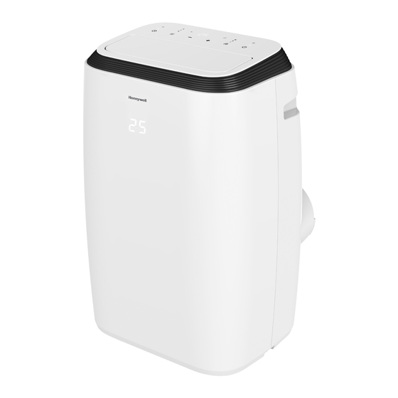
- Page 8 THANK YOU Congratulations on your purchase of this Honeywell Local Air Conditioner. Regarding the information pertaining to the installation, handling, servicing, cleaning and disposal of the appliance, please refer to the below paragraph of the manual. USER TIPS Local Air Conditioners are ideal for spot cooling. The compressor, condenser and evaporator are housed in a compact unit.
-
Page 9: Parts Description
PARTS DESCRIPTION 1) Louver Upper Rubber Drain Plug (Dehumidifying Mode) 2) Control panel Drain Tube (For Continuous Drain) 3) Handle 10) Power Cord Winder 4) Casters 11) Lower Dust Filter 5) Remote Control 12) Lower Rubber Drain Plug (Air Conditioning Mode) 6) Hose Connector 13) Storage Plug for Power Cord 7) Upper Dust Filter... -
Page 10: Installation
INSTALLATION It is important that the installation instructions below are followed for successful installation of this Local Air Conditioner. Please call Customer Support if you have any difficulties or queries regarding these installation procedures. Installation Kit: 1. Window Bracket Kit (1 Set) 4. - Page 11 INSTALLATION (CONTINUED) Window Bracket Kit: Part A: Part B Part A + B: Min. Length 19.8” (50.5cm) Min. Length 27.9” (71.0cm) Max.Length 39.2” (99.5cm) Horizontal Sliding Window Vertical Sliding Window This window kit is designed to fit most standard sliding windows. If your window is outside of the size parameters as outlined above, the window bracket can be cut shorter to fit by bringing it to a nearby hardware store.
- Page 12 INSTALLATION (CONTINUED) 3. Connect the window bracket to the window bracket panel adapter. Ensure that all connections are tight and installed properly. 4. Connect the window bracket to the window. Horizontal Sliding Window Vertical Sliding Window 5. The Portable Air Conditioner is now ready to use.
- Page 13 INSTALLATION (CONTINUED) IMPORTANT: Do not replace or lengthen the hose as this could cause the unit to malfunction. The length of the hose is scientifically determined by the specifications and airflow of the air conditioner. Extending the hose beyond the specified dimensions can cause heat to collect or flow back into the air conditioner causing the unit to malfunction.
-
Page 14: Use And Operation
USE AND OPERATION CONTROL PANEL 1) Display screen 5) Timer / Temperature Set Controls 2) Power Control 6) Mode Control 3) Fan Speed Control 7) Timer Control 4) Swing Control Indicator Light 8) Sleep Control FUNCTION BUTTONS POWER CONTROL Press to turn ON/OFF the unit. -
Page 15: Mode Control
USE AND OPERATION (CONTINUED) FUNCTION BUTTONS (CONTINUED) MODE CONTROL Settings: Air Conditioning, Dehumidifying, Fan. The corresponding indicator light will illuminate to indicate the current mode setting. • Air Conditioning Mode (COOL) Adjust fan speed and air temperature to suit your desired comfort level. Temperature setting range is 60°F - 87.8 °F (16°C - 31°C). -
Page 16: Timer Control
USE AND OPERATION (CONTINUED) FUNCTION BUTTONS (CONTINUED) TIMER CONTROL While the unit is turned on, press the timer button then press the to select the number of hours you would like the unit to continue to run. The unit will turn on/off automatically. AUTO TURN OFF: While unit is running, press the button to select the number of hours you want the unit to... -
Page 17: Remote Control
USE AND OPERATION (CONTINUED) REMOTE CONTROL All key functions can be accessed from the remote control. Timer / Temperature Set Control °C / °F Control • Press to switch temperature between In timer mode, press Centigrade and Fahrenheit. to adjust the time setting for 1 hour intervals. -
Page 18: Cleaning And Maintenance
CLEANING AND MAINTENANCE Appliance Maintenance: Turn off the appliance before disconnecting the power supply. Only clean the appliance with a soft dry cloth. Dust Filter Maintenance: The dust filter is to be cleaned every two weeks to maintain air cooling efficiency. Please follow the below instructions for cleaning the dust filters: Switch off and unplug the Local Air Conditioner from the electrical outlet. - Page 19 CLEANING AND MAINTENANCE (CONTINUED) End of Season Storage and Maintenance: If the appliance will not be used for a long time, follow these steps: Be sure to drain the left-over water condensation. Remove the lower drain plug and use a drain pan to collect the water (make sure to replace the deain plug cap when finished).
-
Page 20: Water Condensation Drainage
WATER CONDENSATION DRAINAGE When there is excess water condensation inside the unit, the air conditioner stops running and shows a warning light (the WATER FULL indicator illuminates with a red light). This indicates that the water condensation needs to be drained using the following procedures: Manual Draining in Cooling, Dehumidifying Modes Water may need to be drained in high humidity areas. -
Page 21: Troubleshooting Guide
TROUBLESHOOTING GUIDE The following troubleshooting guide addresses the most common problems. If problems persist, call customer support. Unplug and disconnect the appliance from the power source before attempting to troubleshoot. PROBLEM POSSIBLE CAUSE SOLUTION No electricity. Check for power. The air Batteries in the remote conditioning control need to be... - Page 22 TROUBLESHOOTING GUIDE (CONTINUED) PROBLEM POSSIBLE CAUSE SOLUTION A door or window is open. Make sure the window or door is closed. The dust filter is dirty. Clean the dust filter. Reinstall hose properly The hose is detached. (refer to Installation section). Runs but not Temperature setting is Reduce temperature setting.
-
Page 23: Error Code Guide
ERROR CODE GUIDE ERROR CODE POSSIBLE CAUSES SUGGESTED REMEDIES Replace room temperature sensor (the unit can also work without replacement.) “E0” Room temperature sensor failed Please contact the Customer Service Center. Replace condenser temperature sensor . “E1” Condenser temperature sensor failed Please contact the Customer Service Center. - Page 24 JMATEK Limited Made in China © 2021 JMATEK Limited. All rights reserved. Rykadan Capital Tower, The Honeywell Trademark is used under license Kwun Tong, Hong Kong from Honeywell International Inc. Phone: 852-2559-5522 Honeywell International Inc. makes no representations or warranties with respect to this product.